EP1645792A2 - Dispositif de perçage - Google Patents
Dispositif de perçage Download PDFInfo
- Publication number
- EP1645792A2 EP1645792A2 EP05017686A EP05017686A EP1645792A2 EP 1645792 A2 EP1645792 A2 EP 1645792A2 EP 05017686 A EP05017686 A EP 05017686A EP 05017686 A EP05017686 A EP 05017686A EP 1645792 A2 EP1645792 A2 EP 1645792A2
- Authority
- EP
- European Patent Office
- Prior art keywords
- locking disc
- housing
- tapping device
- der
- housing part
- Prior art date
- Legal status (The legal status is an assumption and is not a legal conclusion. Google has not performed a legal analysis and makes no representation as to the accuracy of the status listed.)
- Granted
Links
Images
Classifications
-
- F—MECHANICAL ENGINEERING; LIGHTING; HEATING; WEAPONS; BLASTING
- F16—ENGINEERING ELEMENTS AND UNITS; GENERAL MEASURES FOR PRODUCING AND MAINTAINING EFFECTIVE FUNCTIONING OF MACHINES OR INSTALLATIONS; THERMAL INSULATION IN GENERAL
- F16L—PIPES; JOINTS OR FITTINGS FOR PIPES; SUPPORTS FOR PIPES, CABLES OR PROTECTIVE TUBING; MEANS FOR THERMAL INSULATION IN GENERAL
- F16L41/00—Branching pipes; Joining pipes to walls
- F16L41/08—Joining pipes to walls or pipes, the joined pipe axis being perpendicular to the plane of a wall or to the axis of another pipe
- F16L41/16—Joining pipes to walls or pipes, the joined pipe axis being perpendicular to the plane of a wall or to the axis of another pipe the branch pipe comprising fluid cut-off means
-
- F—MECHANICAL ENGINEERING; LIGHTING; HEATING; WEAPONS; BLASTING
- F16—ENGINEERING ELEMENTS AND UNITS; GENERAL MEASURES FOR PRODUCING AND MAINTAINING EFFECTIVE FUNCTIONING OF MACHINES OR INSTALLATIONS; THERMAL INSULATION IN GENERAL
- F16K—VALVES; TAPS; COCKS; ACTUATING-FLOATS; DEVICES FOR VENTING OR AERATING
- F16K3/00—Gate valves or sliding valves, i.e. cut-off apparatus with closing members having a sliding movement along the seat for opening and closing
- F16K3/02—Gate valves or sliding valves, i.e. cut-off apparatus with closing members having a sliding movement along the seat for opening and closing with flat sealing faces; Packings therefor
- F16K3/04—Gate valves or sliding valves, i.e. cut-off apparatus with closing members having a sliding movement along the seat for opening and closing with flat sealing faces; Packings therefor with pivoted closure members
- F16K3/06—Gate valves or sliding valves, i.e. cut-off apparatus with closing members having a sliding movement along the seat for opening and closing with flat sealing faces; Packings therefor with pivoted closure members in the form of closure plates arranged between supply and discharge passages
- F16K3/08—Gate valves or sliding valves, i.e. cut-off apparatus with closing members having a sliding movement along the seat for opening and closing with flat sealing faces; Packings therefor with pivoted closure members in the form of closure plates arranged between supply and discharge passages with circular plates rotatable around their centres
- F16K3/085—Gate valves or sliding valves, i.e. cut-off apparatus with closing members having a sliding movement along the seat for opening and closing with flat sealing faces; Packings therefor with pivoted closure members in the form of closure plates arranged between supply and discharge passages with circular plates rotatable around their centres the axis of supply passage and the axis of discharge passage being coaxial and parallel to the axis of rotation of the plates
Definitions
- the invention relates to a device for drilling a pipeline, which serves to guide a medium, for example a gas or a liquid.
- a medium for example a gas or a liquid.
- tapping devices are also used in the operation of the pipeline, thus, when the pipeline leads a pressurized medium. See DE 203 05 736 U1 or DE 20 2004 003 807 U1.
- the essential components of such a device are the following:
- the device comprises a two-part housing.
- the one, first housing part (lower part) is placed on the pipe and fixed to this. It is accordingly designed such that it comprises the outer surface of the pipe on a part of its circumference. The fixation is done by pipe clamps or straps.
- a second housing part (upper part) is placed on the first housing part. Between these two is a locking disc.
- the first housing part has a connection piece, which produces a conductive connection to the outside after drilling through the wall of the pipeline.
- the second housing part has a guide bush for inserting a drill and the connection of a pipeline.
- the locking disc has a bore. It is movable between a working position and a locking position. In the working position, the connecting piece of the first housing part, the bore of the locking disk and the guide bush of the second housing part are aligned with each other. In the locked position it locks the connecting piece of the first housing part against the guide bushing of the second housing part.
- the disc is provided on its outer periphery with a toothing. It is provided a pinion whose teeth engage in the toothing of the locking disc.
- the bore is arranged eccentrically with respect to the axis of rotation of the locking disc. The locking disc can be rotated by means of the pinion between the working position and the locking position.
- the locking disc is sealed against both the connecting piece of the first housing part and against the guide bush of the second housing part.
- sealing rings are provided on both sides of the locking disc.
- One of these sealing rings is located in the first housing part, namely where its connection piece adjoins the main line near surface of the locking disk.
- the second sealing ring is located in the second housing part, namely, where the guide nozzle adjacent to the main line remote area of the locking disc.
- the sealing effect of the two sealing rings is ensured when the bore of the locking disc is in the working position (first sealing position) in which the two sealing rings enclose the circumference of the bore, and thus a conductive connection between the connecting piece and the guide bushing through the bore of the locking disc passes through.
- Another disadvantage is that when moving or moving the locking disc between its two positions operating medium can penetrate into the housing interior and stops there.
- the locking disk is damaged by the drill or by drilling chips during the tapping process. This occurs especially when the locking disc is not completely in its working position, thus not fully open. In subsequent operations of the locking disc namely moves the damaged areas over the seals. These are damaged here, so that they no longer achieve a tight conclusion.
- the invention has for its object to design a tapping device of the type described above such that the risk of deposits of unwanted particles or even the lingering of medium in dead spaces is reduced or avoided. It should therefore be as little as possible deposits, neither on the locking disk facing housing surfaces, still on the locking disc itself. Furthermore, damage caused by errors in drilling or incomplete opening of the locking disc or adhering to the drill chips when moving out of the drill from the device become.
- sealing material are elastomeric materials such as rubber or other materials into consideration.
- a locking disk according to the invention is generally constructed of a metallic core, for example of stainless steel, and a coating applied thereto. But it is also conceivable to produce the entire locking disc of a corresponding material.
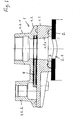
- the tapping device shown in Figure 1 comprises a housing 1. This comprises a first housing part 1.1 and a second housing part 1.2.
- the second housing part 1.2 sits on a pipe 2.
- an elastomeric seal 3 is interposed.
- the pipeline 2 is already provided with a bore 2.1.
- the essential component of the device is a locking disc 4. This comprises a steel core 4.1 and a plastic coating 4.2.
- the first housing part comprises a connection piece 1.1.1.
- the second housing part comprises a guide bushing 1.2.1. This has an internal thread and serves to receive a drilling tool, not shown here or the connection of another pipeline.
- housing part 1.2.2 This contains a pinion, not shown here.
- the locking disc 4 has a part of its circumference a sprocket on.
- the ring gear of the locking disc 4 and the teeth of the pinion mesh with each other.
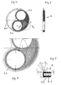
- Figures 2 to 5 show the locking disc 4 in their details.
- the bore 4.3 of the locking disc 4 also the shut-4.4, which shuts off the medium in the locked position.
- a ring gear 4.5 extends only over part of the circumference of the locking disc 4 - in the present case by less than 180 degrees.
- the decisive factor is the coating, which in the present case consists of an elastomer.
- the coating surrounds the bore 4.3 and the shut-off surface 4.4 of the locking disc 4, further those intermediate surface area of the locking disc 4, which faces the ring gear 4.5.
- the coated surface area is approximately kidney-shaped.
- the coating has circular-arc-shaped ribs. These ribs form sealing lips. They ensure a permanent sealing pressure between the two housing parts 1.1 and 1.2 over the entire Vermosweg the locking disc away. In this way it is prevented that operating medium penetrates into the housing, that is in the spaces between the locking disc 4 on the one hand and the facing surfaces of the two housing parts.
- valleys located between the rib segments serve as a displacement space for the elastomeric material, which is displaced in the installed state under pressure.
- FIG. 5 shows that the first sealing rib has a somewhat different configuration than the subsequent ones and also comprises more material. It is therefore particularly strong and has a steeper input edge, as the subsequent sealing rib segments. In addition, it is slightly higher than the other sealing rib segments - see the figures.
- the invention is not only applicable to locking discs of the type shown here, thus in such locking discs, which are circular and have an eccentric bore with respect to its axis of rotation. According to the invention, the invention can also be applied to locking discs which are linearly displaceable between the locking position and the working position.
- the locking disc 4 may be made entirely of an elastomeric material. It can also consist of a plastic core and an elastomeric coating.
Landscapes
- Engineering & Computer Science (AREA)
- General Engineering & Computer Science (AREA)
- Mechanical Engineering (AREA)
- Gasket Seals (AREA)
- Processing Of Stones Or Stones Resemblance Materials (AREA)
- Drilling And Boring (AREA)
- Earth Drilling (AREA)
- Massaging Devices (AREA)
- Vending Machines For Individual Products (AREA)
Applications Claiming Priority (1)
| Application Number | Priority Date | Filing Date | Title |
|---|---|---|---|
| DE102004047787A DE102004047787B3 (de) | 2004-10-01 | 2004-10-01 | Anbohrvorrichtung |
Publications (3)
| Publication Number | Publication Date |
|---|---|
| EP1645792A2 true EP1645792A2 (fr) | 2006-04-12 |
| EP1645792A3 EP1645792A3 (fr) | 2006-05-03 |
| EP1645792B1 EP1645792B1 (fr) | 2008-03-05 |
Family
ID=35549783
Family Applications (1)
| Application Number | Title | Priority Date | Filing Date |
|---|---|---|---|
| EP05017686A Expired - Lifetime EP1645792B1 (fr) | 2004-10-01 | 2005-08-13 | Dispositif de perçage |
Country Status (3)
| Country | Link |
|---|---|
| EP (1) | EP1645792B1 (fr) |
| AT (1) | ATE388365T1 (fr) |
| DE (2) | DE102004047787B3 (fr) |
Families Citing this family (2)
| Publication number | Priority date | Publication date | Assignee | Title |
|---|---|---|---|---|
| DE102009056336A1 (de) | 2009-12-01 | 2011-06-09 | Erhard Gmbh & Co. Kg | Rohrkupplungssystem, insbesondere für eine Anbohrvorrichtung |
| DE102016209089A1 (de) | 2016-05-25 | 2017-11-30 | Düker Gmbh & Co. Kgaa | Anschlussarmatur |
Citations (2)
| Publication number | Priority date | Publication date | Assignee | Title |
|---|---|---|---|---|
| DE20305736U1 (de) | 2003-04-04 | 2003-06-05 | Hawle Armaturen GmbH, 83395 Freilassing | Anbohrarmatur |
| DE202004003807U1 (de) | 2004-03-11 | 2004-05-13 | Ernst Zürn GmbH & Co. KG | Anbohrarmatur |
Family Cites Families (1)
| Publication number | Priority date | Publication date | Assignee | Title |
|---|---|---|---|---|
| FR821841A (fr) * | 1937-05-13 | 1937-12-14 | Dispositif de fermeture pour collier de prise en charge |
-
2004
- 2004-10-01 DE DE102004047787A patent/DE102004047787B3/de not_active Expired - Fee Related
-
2005
- 2005-08-13 DE DE502005003067T patent/DE502005003067D1/de not_active Expired - Lifetime
- 2005-08-13 AT AT05017686T patent/ATE388365T1/de active
- 2005-08-13 EP EP05017686A patent/EP1645792B1/fr not_active Expired - Lifetime
Patent Citations (2)
| Publication number | Priority date | Publication date | Assignee | Title |
|---|---|---|---|---|
| DE20305736U1 (de) | 2003-04-04 | 2003-06-05 | Hawle Armaturen GmbH, 83395 Freilassing | Anbohrarmatur |
| DE202004003807U1 (de) | 2004-03-11 | 2004-05-13 | Ernst Zürn GmbH & Co. KG | Anbohrarmatur |
Also Published As
| Publication number | Publication date |
|---|---|
| EP1645792A3 (fr) | 2006-05-03 |
| ATE388365T1 (de) | 2008-03-15 |
| DE102004047787B3 (de) | 2006-05-11 |
| EP1645792B1 (fr) | 2008-03-05 |
| DE502005003067D1 (de) | 2008-04-17 |
Similar Documents
| Publication | Publication Date | Title |
|---|---|---|
| DE2252284C3 (de) | Dichtungseinrichtung für Rohrhängevorrichtungen von Tiefbohrungen | |
| DE19746041A1 (de) | Steuerventil mit verbessertem Käfig | |
| CH632074A5 (de) | Dichtungsvorrichtung an einem druckfluidumzylinder. | |
| DE2933512A1 (de) | Proben-einspritzventil | |
| DE2927244C2 (fr) | ||
| EP3201498B1 (fr) | Serrure à crochet destinée à un joint d'étanchéité rectangulaire ainsi que joint d'étanchéité rectangulaire comportant une serrure à crochet de ce type | |
| DE202014104058U1 (de) | Verschluss mit den Öffnungszustand anzeigenden Signalring | |
| EP1645792B1 (fr) | Dispositif de perçage | |
| EP0393560A2 (fr) | Appareil de perçage | |
| DE102009019192A1 (de) | Kurzraupenpistole | |
| DE102007025375A1 (de) | Spindeldichtung | |
| WO2016020058A1 (fr) | Joint d'étanchéité rectangulaire servant à rendre étanche un passage, destiné en particulier à des fluides | |
| DE2059905C2 (de) | Verfahren und Vorrichtung zum Absperren des Strömungswegs in einer unter Druck stehenden Rohrleitung | |
| DE202014006271U1 (de) | Hakenschloss für eine Rechteckdichtung sowie eine ein derartiges Hakenschloss aufweisende Rechteckdichtung | |
| DE3009983C2 (de) | U-förmiges Dichtelement | |
| DE3726258C2 (de) | Vorrichtung zum Absperren von rohrförmigen Transportleitungen für Flüssigkeit oder Gas | |
| DE102014011534A1 (de) | Rechteckdichtung zur Abdichtung einer Durchführung, insbesonder für Fluide | |
| DE2918555A1 (de) | Anbohrschelle | |
| EP1336780B1 (fr) | Joint secondaire pour dispositif de joint d'étanchéité à bague glissante | |
| DE2655935C2 (de) | Aufspreizbare Vorrichtung zum Befestigen von rohrförmigen Wickelhülsen auf Spindeln | |
| DE102009006808A1 (de) | Gelenkdichtung für Spritzgießmaschinen | |
| DE3237226A1 (de) | Anpressbares schiebefenster | |
| DE102005059563A1 (de) | Dosierpumpe | |
| DE102025110368A1 (de) | Stopfbuchsen-Reparaturwerkzeug, Stopfbuchsen-Reparaturwerkzeug Anordnung und Verfahren zur Reparatur einer Stopfbuchse in einem Hochdruckventil | |
| DE102012003647B4 (de) | Regulierschraube aus Kunststoff zum Justieren von Durchflußmessern sowie Durchflußmesser mit einer Regulierschraube |
Legal Events
| Date | Code | Title | Description |
|---|---|---|---|
| PUAI | Public reference made under article 153(3) epc to a published international application that has entered the european phase |
Free format text: ORIGINAL CODE: 0009012 |
|
| PUAL | Search report despatched |
Free format text: ORIGINAL CODE: 0009013 |
|
| AK | Designated contracting states |
Kind code of ref document: A2 Designated state(s): AT BE BG CH CY CZ DE DK EE ES FI FR GB GR HU IE IS IT LI LT LU LV MC NL PL PT RO SE SI SK TR |
|
| AX | Request for extension of the european patent |
Extension state: AL BA HR MK YU |
|
| AK | Designated contracting states |
Kind code of ref document: A3 Designated state(s): AT BE BG CH CY CZ DE DK EE ES FI FR GB GR HU IE IS IT LI LT LU LV MC NL PL PT RO SE SI SK TR |
|
| AX | Request for extension of the european patent |
Extension state: AL BA HR MK YU |
|
| 17P | Request for examination filed |
Effective date: 20060707 |
|
| AKX | Designation fees paid |
Designated state(s): AT BE BG CH CY CZ DE DK EE ES FI FR GB GR HU IE IS IT LI LT LU LV MC NL PL PT RO SE SI SK TR |
|
| GRAP | Despatch of communication of intention to grant a patent |
Free format text: ORIGINAL CODE: EPIDOSNIGR1 |
|
| GRAS | Grant fee paid |
Free format text: ORIGINAL CODE: EPIDOSNIGR3 |
|
| GRAA | (expected) grant |
Free format text: ORIGINAL CODE: 0009210 |
|
| AK | Designated contracting states |
Kind code of ref document: B1 Designated state(s): AT BE BG CH CY CZ DE DK EE ES FI FR GB GR HU IE IS IT LI LT LU LV MC NL PL PT RO SE SI SK TR |
|
| REG | Reference to a national code |
Ref country code: GB Ref legal event code: FG4D Free format text: NOT ENGLISH |
|
| REG | Reference to a national code |
Ref country code: CH Ref legal event code: EP |
|
| REG | Reference to a national code |
Ref country code: IE Ref legal event code: FG4D Free format text: LANGUAGE OF EP DOCUMENT: GERMAN |
|
| REF | Corresponds to: |
Ref document number: 502005003067 Country of ref document: DE Date of ref document: 20080417 Kind code of ref document: P |
|
| PG25 | Lapsed in a contracting state [announced via postgrant information from national office to epo] |
Ref country code: FI Free format text: LAPSE BECAUSE OF FAILURE TO SUBMIT A TRANSLATION OF THE DESCRIPTION OR TO PAY THE FEE WITHIN THE PRESCRIBED TIME-LIMIT Effective date: 20080305 Ref country code: ES Free format text: LAPSE BECAUSE OF FAILURE TO SUBMIT A TRANSLATION OF THE DESCRIPTION OR TO PAY THE FEE WITHIN THE PRESCRIBED TIME-LIMIT Effective date: 20080616 |
|
| PG25 | Lapsed in a contracting state [announced via postgrant information from national office to epo] |
Ref country code: LV Free format text: LAPSE BECAUSE OF FAILURE TO SUBMIT A TRANSLATION OF THE DESCRIPTION OR TO PAY THE FEE WITHIN THE PRESCRIBED TIME-LIMIT Effective date: 20080305 Ref country code: PL Free format text: LAPSE BECAUSE OF FAILURE TO SUBMIT A TRANSLATION OF THE DESCRIPTION OR TO PAY THE FEE WITHIN THE PRESCRIBED TIME-LIMIT Effective date: 20080305 Ref country code: SI Free format text: LAPSE BECAUSE OF FAILURE TO SUBMIT A TRANSLATION OF THE DESCRIPTION OR TO PAY THE FEE WITHIN THE PRESCRIBED TIME-LIMIT Effective date: 20080305 |
|
| REG | Reference to a national code |
Ref country code: IE Ref legal event code: FD4D |
|
| PG25 | Lapsed in a contracting state [announced via postgrant information from national office to epo] |
Ref country code: SE Free format text: LAPSE BECAUSE OF FAILURE TO SUBMIT A TRANSLATION OF THE DESCRIPTION OR TO PAY THE FEE WITHIN THE PRESCRIBED TIME-LIMIT Effective date: 20080605 Ref country code: PT Free format text: LAPSE BECAUSE OF FAILURE TO SUBMIT A TRANSLATION OF THE DESCRIPTION OR TO PAY THE FEE WITHIN THE PRESCRIBED TIME-LIMIT Effective date: 20080805 Ref country code: CZ Free format text: LAPSE BECAUSE OF FAILURE TO SUBMIT A TRANSLATION OF THE DESCRIPTION OR TO PAY THE FEE WITHIN THE PRESCRIBED TIME-LIMIT Effective date: 20080305 Ref country code: SK Free format text: LAPSE BECAUSE OF FAILURE TO SUBMIT A TRANSLATION OF THE DESCRIPTION OR TO PAY THE FEE WITHIN THE PRESCRIBED TIME-LIMIT Effective date: 20080305 |
|
| PG25 | Lapsed in a contracting state [announced via postgrant information from national office to epo] |
Ref country code: RO Free format text: LAPSE BECAUSE OF FAILURE TO SUBMIT A TRANSLATION OF THE DESCRIPTION OR TO PAY THE FEE WITHIN THE PRESCRIBED TIME-LIMIT Effective date: 20080305 |
|
| EN | Fr: translation not filed | ||
| PG25 | Lapsed in a contracting state [announced via postgrant information from national office to epo] |
Ref country code: IS Free format text: LAPSE BECAUSE OF FAILURE TO SUBMIT A TRANSLATION OF THE DESCRIPTION OR TO PAY THE FEE WITHIN THE PRESCRIBED TIME-LIMIT Effective date: 20080705 |
|
| PLBE | No opposition filed within time limit |
Free format text: ORIGINAL CODE: 0009261 |
|
| STAA | Information on the status of an ep patent application or granted ep patent |
Free format text: STATUS: NO OPPOSITION FILED WITHIN TIME LIMIT |
|
| PG25 | Lapsed in a contracting state [announced via postgrant information from national office to epo] |
Ref country code: IE Free format text: LAPSE BECAUSE OF FAILURE TO SUBMIT A TRANSLATION OF THE DESCRIPTION OR TO PAY THE FEE WITHIN THE PRESCRIBED TIME-LIMIT Effective date: 20080305 Ref country code: LT Free format text: LAPSE BECAUSE OF FAILURE TO SUBMIT A TRANSLATION OF THE DESCRIPTION OR TO PAY THE FEE WITHIN THE PRESCRIBED TIME-LIMIT Effective date: 20080305 Ref country code: DK Free format text: LAPSE BECAUSE OF FAILURE TO SUBMIT A TRANSLATION OF THE DESCRIPTION OR TO PAY THE FEE WITHIN THE PRESCRIBED TIME-LIMIT Effective date: 20080305 |
|
| 26N | No opposition filed |
Effective date: 20081208 |
|
| PG25 | Lapsed in a contracting state [announced via postgrant information from national office to epo] |
Ref country code: MC Free format text: LAPSE BECAUSE OF NON-PAYMENT OF DUE FEES Effective date: 20080831 |
|
| PG25 | Lapsed in a contracting state [announced via postgrant information from national office to epo] |
Ref country code: BG Free format text: LAPSE BECAUSE OF FAILURE TO SUBMIT A TRANSLATION OF THE DESCRIPTION OR TO PAY THE FEE WITHIN THE PRESCRIBED TIME-LIMIT Effective date: 20080605 Ref country code: EE Free format text: LAPSE BECAUSE OF FAILURE TO SUBMIT A TRANSLATION OF THE DESCRIPTION OR TO PAY THE FEE WITHIN THE PRESCRIBED TIME-LIMIT Effective date: 20080305 Ref country code: FR Free format text: LAPSE BECAUSE OF FAILURE TO SUBMIT A TRANSLATION OF THE DESCRIPTION OR TO PAY THE FEE WITHIN THE PRESCRIBED TIME-LIMIT Effective date: 20081226 |
|
| PG25 | Lapsed in a contracting state [announced via postgrant information from national office to epo] |
Ref country code: IT Free format text: LAPSE BECAUSE OF FAILURE TO SUBMIT A TRANSLATION OF THE DESCRIPTION OR TO PAY THE FEE WITHIN THE PRESCRIBED TIME-LIMIT Effective date: 20080305 |
|
| PG25 | Lapsed in a contracting state [announced via postgrant information from national office to epo] |
Ref country code: CY Free format text: LAPSE BECAUSE OF FAILURE TO SUBMIT A TRANSLATION OF THE DESCRIPTION OR TO PAY THE FEE WITHIN THE PRESCRIBED TIME-LIMIT Effective date: 20080305 |
|
| PG25 | Lapsed in a contracting state [announced via postgrant information from national office to epo] |
Ref country code: HU Free format text: LAPSE BECAUSE OF FAILURE TO SUBMIT A TRANSLATION OF THE DESCRIPTION OR TO PAY THE FEE WITHIN THE PRESCRIBED TIME-LIMIT Effective date: 20080906 |
|
| PG25 | Lapsed in a contracting state [announced via postgrant information from national office to epo] |
Ref country code: TR Free format text: LAPSE BECAUSE OF FAILURE TO SUBMIT A TRANSLATION OF THE DESCRIPTION OR TO PAY THE FEE WITHIN THE PRESCRIBED TIME-LIMIT Effective date: 20080305 |
|
| PG25 | Lapsed in a contracting state [announced via postgrant information from national office to epo] |
Ref country code: GR Free format text: LAPSE BECAUSE OF FAILURE TO SUBMIT A TRANSLATION OF THE DESCRIPTION OR TO PAY THE FEE WITHIN THE PRESCRIBED TIME-LIMIT Effective date: 20080606 |
|
| PGFP | Annual fee paid to national office [announced via postgrant information from national office to epo] |
Ref country code: LU Payment date: 20140822 Year of fee payment: 10 |
|
| PGFP | Annual fee paid to national office [announced via postgrant information from national office to epo] |
Ref country code: CH Payment date: 20140821 Year of fee payment: 10 Ref country code: NL Payment date: 20140821 Year of fee payment: 10 |
|
| PGFP | Annual fee paid to national office [announced via postgrant information from national office to epo] |
Ref country code: AT Payment date: 20140826 Year of fee payment: 10 |
|
| PGFP | Annual fee paid to national office [announced via postgrant information from national office to epo] |
Ref country code: BE Payment date: 20140825 Year of fee payment: 10 |
|
| PG25 | Lapsed in a contracting state [announced via postgrant information from national office to epo] |
Ref country code: LU Free format text: LAPSE BECAUSE OF NON-PAYMENT OF DUE FEES Effective date: 20150813 |
|
| REG | Reference to a national code |
Ref country code: CH Ref legal event code: PL |
|
| REG | Reference to a national code |
Ref country code: AT Ref legal event code: MM01 Ref document number: 388365 Country of ref document: AT Kind code of ref document: T Effective date: 20150813 |
|
| PG25 | Lapsed in a contracting state [announced via postgrant information from national office to epo] |
Ref country code: CH Free format text: LAPSE BECAUSE OF NON-PAYMENT OF DUE FEES Effective date: 20150831 Ref country code: LI Free format text: LAPSE BECAUSE OF NON-PAYMENT OF DUE FEES Effective date: 20150831 |
|
| REG | Reference to a national code |
Ref country code: NL Ref legal event code: MM Effective date: 20150901 |
|
| PG25 | Lapsed in a contracting state [announced via postgrant information from national office to epo] |
Ref country code: AT Free format text: LAPSE BECAUSE OF NON-PAYMENT OF DUE FEES Effective date: 20150813 |
|
| PG25 | Lapsed in a contracting state [announced via postgrant information from national office to epo] |
Ref country code: NL Free format text: LAPSE BECAUSE OF NON-PAYMENT OF DUE FEES Effective date: 20150901 |
|
| PG25 | Lapsed in a contracting state [announced via postgrant information from national office to epo] |
Ref country code: BE Free format text: LAPSE BECAUSE OF NON-PAYMENT OF DUE FEES Effective date: 20150831 |
|
| REG | Reference to a national code |
Ref country code: DE Ref legal event code: R082 Ref document number: 502005003067 Country of ref document: DE Representative=s name: HOEFER & PARTNER PATENTANWAELTE MBB, DE |
|
| PGFP | Annual fee paid to national office [announced via postgrant information from national office to epo] |
Ref country code: GB Payment date: 20230824 Year of fee payment: 19 |
|
| PGFP | Annual fee paid to national office [announced via postgrant information from national office to epo] |
Ref country code: DE Payment date: 20230621 Year of fee payment: 19 |
|
| REG | Reference to a national code |
Ref country code: DE Ref legal event code: R119 Ref document number: 502005003067 Country of ref document: DE |
|
| GBPC | Gb: european patent ceased through non-payment of renewal fee |
Effective date: 20240813 |
|
| PG25 | Lapsed in a contracting state [announced via postgrant information from national office to epo] |
Ref country code: DE Free format text: LAPSE BECAUSE OF NON-PAYMENT OF DUE FEES Effective date: 20250301 |
|
| PG25 | Lapsed in a contracting state [announced via postgrant information from national office to epo] |
Ref country code: GB Free format text: LAPSE BECAUSE OF NON-PAYMENT OF DUE FEES Effective date: 20240813 |