EP1645945A2 - Appareil de traitement d'informations et programmes utilisés dans un appareil de traitement d'informations - Google Patents
Appareil de traitement d'informations et programmes utilisés dans un appareil de traitement d'informations Download PDFInfo
- Publication number
- EP1645945A2 EP1645945A2 EP05021744A EP05021744A EP1645945A2 EP 1645945 A2 EP1645945 A2 EP 1645945A2 EP 05021744 A EP05021744 A EP 05021744A EP 05021744 A EP05021744 A EP 05021744A EP 1645945 A2 EP1645945 A2 EP 1645945A2
- Authority
- EP
- European Patent Office
- Prior art keywords
- display
- information
- mode
- processing apparatus
- unit
- Prior art date
- Legal status (The legal status is an assumption and is not a legal conclusion. Google has not performed a legal analysis and makes no representation as to the accuracy of the status listed.)
- Withdrawn
Links
Images



Classifications
-
- G—PHYSICS
- G06—COMPUTING OR CALCULATING; COUNTING
- G06F—ELECTRIC DIGITAL DATA PROCESSING
- G06F3/00—Input arrangements for transferring data to be processed into a form capable of being handled by the computer; Output arrangements for transferring data from processing unit to output unit, e.g. interface arrangements
- G06F3/01—Input arrangements or combined input and output arrangements for interaction between user and computer
- G06F3/048—Interaction techniques based on graphical user interfaces [GUI]
- G06F3/0487—Interaction techniques based on graphical user interfaces [GUI] using specific features provided by the input device, e.g. functions controlled by the rotation of a mouse with dual sensing arrangements, or of the nature of the input device, e.g. tap gestures based on pressure sensed by a digitiser
- G06F3/0488—Interaction techniques based on graphical user interfaces [GUI] using specific features provided by the input device, e.g. functions controlled by the rotation of a mouse with dual sensing arrangements, or of the nature of the input device, e.g. tap gestures based on pressure sensed by a digitiser using a touch-screen or digitiser, e.g. input of commands through traced gestures
-
- G—PHYSICS
- G06—COMPUTING OR CALCULATING; COUNTING
- G06F—ELECTRIC DIGITAL DATA PROCESSING
- G06F3/00—Input arrangements for transferring data to be processed into a form capable of being handled by the computer; Output arrangements for transferring data from processing unit to output unit, e.g. interface arrangements
- G06F3/01—Input arrangements or combined input and output arrangements for interaction between user and computer
- G06F3/048—Interaction techniques based on graphical user interfaces [GUI]
- G06F3/0484—Interaction techniques based on graphical user interfaces [GUI] for the control of specific functions or operations, e.g. selecting or manipulating an object, an image or a displayed text element, setting a parameter value or selecting a range
- G06F3/0486—Drag-and-drop
Definitions
- the present invention contains subject matter related to Japanese Patent Application JP 2004-292409 filed in the Japanese Patent Office on October 5, 2004, the entire contents of which being incorporated herein by reference.
- the present invention relates to a technology used for improving operatability to specify a display range in an information-processing apparatus having a configuration allowing the user to enter operation inputs while viewing a screen display by using a coordinate input unit (or a coordinate read unit) such as a touch panel.
- an operation input configuration of an information-processing apparatus such as a portable computer
- a configuration using an input unit (or a read unit) of an absolute coordinate type examples include a touch panel and a tablet.
- an operation input can be entered to the information-processing apparatus by using a stylus or a finger.
- an application program activated to run under an operating system (hereinafter referred to as OS) executed in the information-processing apparatus for example, the user is capable of carrying out an operation by using a GUI (Graphical User Interface) while viewing information appearing on the display screen of the apparatus.
- GUI Graphic User Interface
- an input pen system having a switching function allowing the user familiar with operations carried out in a GUI environment using a pointing device such as the mouse to enter an operation input in the same operating sense as an apparatus provided with a touch panel as disclosed in some documents.
- An example of the switching function is a function to switch from a right-click facility of the mouse to left-click facility thereof and vice versa.
- Fig. 8 is an explanatory diagram showing a state in which the highest resolution of an absolute coordinate input unit is lower than the resolution of a display screen to be displayed.
- a rectangular frame W in the figure is the display screen whereas a rectangular frame ⁇ having a small area in the display screen W is a display range (or a display area) of the display unit such as a tablet integrated display unit.
- a panning state is a display state in which only a range corresponding to the display area ⁇ is partially displayed on the display screen W. That is to say, a panning state is a display state caused by the fact that the highest resolution of the display unit is lower than the resolution of a display screen. However, deletion of picture data or the like is not taken into consideration.
- the assumed resolution cited above is also referred to as a displayable highest resolution.
- the user is not capable of specifying a position outside the display range ⁇ by operating the touch panel. That is to say, the use of another relative coordinate device for moving a pointer from the display range to another display range in the display screen is indispensable since the function of such a relative coordinate device cannot be implemented by merely operating the touch panel. For example, it is necessary to use a device such as a track point, an operation stick or a mouse to move the pointer to an outside position beyond the boundary of the display range in a desired direction, that is, to move the pointer to an intended display range.
- a device such as a track point, an operation stick or a mouse
- An input operation mode in the panning state is referred to hereafter as a panning mode.
- a panning mode by operating only the absolute coordinate input unit, a desired display range cannot probably be specified, or another device is required, affecting the operatability seen from the user point of view.
- an information-processing apparatus having a configuration in which, when an operation face of an absolute coordinate input unit employed in the information-processing apparatus is touched in a touch operation carried out in a panning mode to move a display operator over a display screen appearing on a display unit employed in the information-processing apparatus, the distance of a movement of the display operator is detected, and the position of a display range on the display screen is then changed by moving the display range by the detected distance where the panning mode is a display-range operation mode allowing the position of a display range to be changed by moving the display range in a state of displaying only a portion of the entire display screen on the display unit.
- a program executed by the information-processing apparatus includes the steps of: determining that an input operation mode has been changed to a display-range operation mode; and changing a display range by moving the display range on a display screen appearing on a display unit employed in the information-processing apparatus by a distance detected as the distance of a movement of a display operator, which is moved over the display screen when an operation face of an absolute coordinate input unit employed in the information-processing apparatus is touched in a touch operation after the input operation mode has been changed to the display-range operation mode.
- a display range in the panning mode where only a portion of the screen appears on the display unit, a display range can be moved to a desired location by merely operating the absolute coordinate input unit.
- another relative coordinate input device is not required in a panning state.
- the present invention effectively allows the configuration of the information-processing apparatus to be simplified and the manufacturing cost thereof to be reduced.
- the present invention is also effective for improving operatability and convenience, which are provided for the user.
- the present invention is suitable for increasing the size of a display unit. Moreover, by further designing the configuration so as to allow the input operation mode to be changed in a cyclic manner by carrying out a touch operation on the specific operation area, the size of the operation area can be reduced to a required minimum.
- the capability of changing and/or switching to a hover mode can implemented with ease is effective for improvement of operatability.
- the hover mode is a mode corresponding to an operation to move a mouse pointer.
- the present invention provides an information-processing apparatus having an absolute coordinate input unit and a display unit, with which the absolute coordinate input unit is integrated.
- the information-processing apparatus has a configuration allowing a display range to be modified in a panning state by operating only the absolute coordinate input unit. It is to be noted that the information-processing apparatus according to an embodiment of the present invention can also be applied to equipment such as a computer, a PDA (Personal Digital Assistant), a variety of video apparatus and an acoustic apparatus.
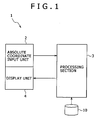
- Fig. 1 is a diagram showing a typical basic configuration of an information-processing apparatus 1 according to the embodiment of the present invention.
- the information-processing apparatus 1 employs a touch panel integrated with a display unit 4 to be described later, and a pen input device or a digitizer or the like.
- a touch panel integrated with a display unit 4 to be described later
- a pen input device or a digitizer or the like When the user specifies a position on an operation face by using a finger, a pen or a stylus, for example, absolute coordinates of the specified position are detected.
- the present invention can be applied to the information-processing apparatus 1 without regard to whether the connection between the pointing device such as an input pen and a main body 5 of the information-processing apparatus 1 is a wire connection or a wireless (or radio) connection.
- a processing unit 3 which is typically a CPU (Central Processing Unit) or a system controller processes information on a position or an operation specified in an operation carried out by the user by using the absolute coordinate input unit 2.
- CPU Central Processing Unit
- a processing unit 3 which is typically a CPU (Central Processing Unit) or a system controller processes information on a position or an operation specified in an operation carried out by the user by using the absolute coordinate input unit 2.
- the display unit 4 is integrated with the absolute coordinate input unit 2.
- a device such as a liquid-crystal display panel is employed. The user is capable of carrying out an input operation or a select operation on the absolute coordinate input unit 2 while viewing a display on the screen of the display unit 4.
- the present invention can be applied to a configuration having an operation section including hardware keys such as operation buttons and switches on the main body of the information-processing apparatus 1 or a configuration allowing an input to be entered or a selection to be specified completely by carrying out an operation on the absolute coordinate input unit 2 without providing such an operation section.
- Fig. 2 is a diagram showing the information-processing apparatus 1 in a simple manner.
- the front face of the main body 5 is provided with an operation display section 6 integrated with a touch panel and a display device.
- an input operation mode can be changed by a specific operation key 7 provided on the main body 5 or a specific operation area 8 provided on the touch panel.
- Operations carried out by the user on the touch panel include the following operations.
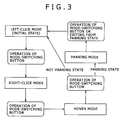
- Fig. 3 is an explanatory diagram showing typical state transitions initiated by operating a specific operation button as transitions between the input operation modes described above.
- the specific operation button used for initiating the mode transitions is referred to hereafter as a mode-switching button.
- the left-click mode is selected. Then, the left-click mode is changed to the right-click mode by operating the mode-switching button.
- the mode-switching button can be operated by pressing the button or by tapping an operation area.
- the right-click mode is changed to the hover mode.
- the hover mode is changed back to the left-click mode if the information-processing apparatus 1 is not in the panning state or the hover mode is changed to the panning mode if the information-processing apparatus 1 is in the panning state.
- the panning mode is changed to the left-click mode if the mode-switching button is operated or if the information-processing apparatus 1 exits from the panning state.
- the input operation mode can be changed in a cyclic manner by operating the mode-switching button as described above, only a single operation button or a single operation area is needed.
- the occupied area can be suppressed to a minimum. That is to say, it is not necessary to provide an operation key 7 on the main body 5 for each mode transition or provide an operation touch section in the operation area 8 for each input operation mode.
- four input operation modes are provided and the number of input operation modes may actually be even larger.
- the number of operation keys 7 and/or the number of occupied areas on the information-processing apparatus will also increase as well. Thus, the display area will be affected.
- the input operation mode can be changed by carrying a touch operation on a specific operation area provided on the touch panel
- no dedicated hardware keys are needed.
- the display area of the display unit can be increased by an amount corresponding to the elimination of the dedicated hardware keys.
- a CRT or a liquid-crystal display device is used as the display unit 4, an image can be displayed at one of a plurality of different resolutions. If the screen resolution is lower than the highest resolution displayable by the display unit 4, the whole screen can typically be displayed on the display unit 4.
- the screen resolution is higher than the highest resolution displayable by the display unit 4, however, only a portion of the screen can be displayed by using an image-processing function of a graphic LSI or the like in the so-called panning state as explained above with reference to Fig. 8.
- the input operation mode can be changed to the panning mode by operating the mode-switching button. Then, an operation carried out by the user on the touch panel is recognized, for example, as a command to move a display range.
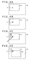
- Figs. 4A to 4D are explanatory diagrams showing operation states in the panning mode.
- Notations W and ⁇ denote the same things as those explained above with reference to Fig. 8.
- the display frames each have a rectangular shape. It is to be noted that the present invention is not to be limited to the rectangular shape. That is to say, any frame shapes may be used.
- Fig. 4A is a diagram showing a screen frame W displayed on the display unit 4 with a frame ⁇ appearing on a portion inside the screen frame W and a pointer (or a cursor) displayed on the frame ⁇ as a display operator 9 having an arrow-like shape.
- the shape of the display operator 9 is changed to a shape provided for the panning mode as shown in Fig. 4B.
- the shape provided for the panning mode is the shape of the palm of a left hand.
- the user carries out an operation to slide a pointing device such as a stylus or a finger over the touch panel with the pointing device kept in a state of being brought into contact with the touch panel, that is, with the pointing device kept in a state of touching the touch panel, as it is.
- the operation to slide a pointing device such as a stylus or a finger over the touch panel with the pointing device kept in a state of being brought into contact with the touch panel is referred to as a drag operation.
- the display range shown so far as a dashed-line frame is moved to the location of another display range shown as a solid-line frame as shown in Fig. 4D.
- a program including a step of implementing this processing is read out from a storage section 10 employed in the information-processing apparatus 1 as shown in Fig. 1 and interpreted by the CPU for execution. That is to say, the core of the processing carried out by the information-processing apparatus 1 is implemented by hardware including the processing unit 3 such as the CPU and a collection of various programs executed by the processing unit 3. By execution of the programs according to information on operations, the following processing steps are carried out.
- the position of a display range in the panning state can be changed by using only the touch panel.
- the mode can be changed from one to another with ease. It is also desirable to assign the function to change the input operation mode to a single operation section so as to achieve simplification of the operation system.
- a case 12 of an information-processing apparatus 11 has a transversally long flat rectangular shape.
- a display device 14 such as a liquid-crystal display device is provided.
- a touch panel is provided on the surface 15 of the display device 14.
- the user is capable of carrying out a select operation and an input operation by specifying a desired position on an operation face through use of a pointing device 16 such as a finger, a dedicated pen or a stylus while viewing the display screen.
- a pointing device 16 such as a finger, a dedicated pen or a stylus while viewing the display screen.
- a variety of operations elements 17, 17 and so on is provided at predetermined locations on the case 12. Examples of the operation elements 17, 17 and so on are buttons and switches. One of the operation elements 17, 17 and so on is a mode-switching button.
- a typical configuration of the operation elements 17, 17 and so on is explained as follows.
- Fig. 6 is a block diagram showing a typical hardware configuration of the information-processing apparatus 11.
- a CPU 101 serving as a control nucleus is connected to a control unit 102 through an FSB (Front Side Bus).
- the control unit 102, other control units and other devices form the processing unit 3 described above.
- the other control units and other devices will be described later.
- the control unit 102 is a component for executing control of a main memory 103 and a graphic function.
- the control unit 102 mainly plays a role for processing data having a large amount at a high speed. In AT compatibility, the control unit 102 is referred to as a north bridge.
- the control unit 102 is connected to the CPU 101, the main memory 103, a control unit 104 and a graphic display unit 105 such as a liquid-crystal display device.
- the control unit 104 is a component mainly for controlling elements such as control devices provided for a user interface and for controlling bus links of devices. In the AT compatibility, the control unit 104 is referred to as a south bridge. In an ISA bridge to the PCI, the control unit 104 plays a role of a bridge between a PCI (Peripheral Component Interconnect) bus and a low-speed bus such as an ISA (Industry Standard Architecture) bus.
- the control unit 104 has the functions of controllers such as an ISA controller and an IDE (Integrated Drive Electronics) controller.
- the PCI bus is connected to a radio LAN (or a W-LAN) serving as a radio communication device 106 and a device 107 for connection with and controlling an external memory and an external apparatus.
- a radio LAN or a W-LAN
- a device 107 for connection with and controlling an external memory and an external apparatus.
- a semiconductor memory device can be employed.
- the device 107 is provided with a control device 108 for reading out and writing data from and into a stick-shaped storage medium and a control device 109 for reading out and writing data from and into a card-shaped storage medium.
- the device 107 has the function of a connection interface with an external apparatus.
- An example of the connection interface is an interface conforming to IEEE 1394 defining specifications of hardware for adding a serial device to a computer.
- the control unit 104 is connected a LAN (Local Area Network) connection device 110 and a USB (Universal Serial Bus) port connected to the touch panel 111.
- LAN Local Area Network
- USB Universal Serial Bus
- An auxiliary storage unit 112 is a drive for driving a disk such as a magnetic or optical disk.
- the auxiliary storage unit 112 is a drive for driving a large-capacity storage medium such as a hard disk.
- the auxiliary storage unit 112 is connected to the control unit 104, which serves as an internal IDE controller.
- An audio codec 113 connected to the control unit 104 is a component for outputting an audio signal obtained as a result of a digital-analog conversion process to a component such as a speaker 114 or head phones 115.
- the audio signal represents a voice or a sound.
- the audio codec 113 carries out a process to convert audio input data into a digital one.
- a storage unit 116 is a memory for storing a control program for driving a computer.
- the storage unit 116 is connected to the control unit 104 and a control unit 117 by using an LPC (Low Pin Count) bus or the like.
- LPC Low Pin Count
- the control unit 117 is a general-purpose unit for controlling a variety of signals. As the control unit 117, for example, an EC (Embedded Controller) is employed. The control unit 117 also controls the power supply of the information-processing apparatus 11 and additional functions of the information-processing apparatus 11. In the case of a portable information-processing apparatus, the control unit 117 is a microcomputer. It is to be noted that, by modifying a control program stored in the storage unit 116, the method for controlling the computer can be changed.
- EC embedded Controller
- An operation section 118 including the operation element 17 provided on the main body of the information-processing apparatus 11 outputs a signal to the control unit 117.
- a connection section 119 for connecting an external apparatus to the information-processing apparatus 11 a USB connector is provided on the main body of the information-processing apparatus 11. The USB connector 119 is also connected to the control unit 104.
- a power-supply section not shown in the figure receives a commercial power-supply voltage from an AC adaptor.
- the information-processing apparatus 11 may be powered by a battery pack serving as DC power supply.
- the battery pack includes secondary batteries or fuel batteries.
- Fig. 7 is an explanatory diagram showing elements composing a software configuration.
- Information on an operation (detected information on pressing or non-pressing button, for example) generated by the mode-switching button serving as one of the operation elements 17 is supplied to a device driver 18 by way of the control unit 117, which is an EC (Embedded Controller) in the embodiment.
- the device driver 18 then forwards the information on an operation to a dynamic link library 19.
- the dynamic link library 19 passes on the information on an operation to an event service 20.
- the event service 20 is a program for monitoring the present setting state of the image resolution and changes in image resolution through a video driver 21. Receiving the information on an operation from the dynamic link library 19, the event service 20 determines a next mode to serve as the destination of a mode transition on the basis of the present image resolution and the present input operation mode. Then, the event service 20 issues a command based on a result of the determination to a touch-panel driver 22.
- the information on an operation carried out on the touch panel 111 has been output to the control unit 104, the information is sent to the OS 23 on an upper layer by way of the touch-panel driver 22.
- the touch-panel driver 22 sets an input operation mode according to the operation information received from the event service 20.
- a message of a mouse event is sent to the OS 23 in accordance with the set mode.
- an operation carried out by the user in the panning mode as described above is recognized as a request for a movement of a display range.
- a movement distance by which the display range is to be moved is computed from coordinates of a drag operation carried out by using a pointing device such as a stylus in the processing to move the display range.
- the computed movement distance is then supplied to the OS 23.
- the event service 20 executes a processing step of managing the setting of dynamic mode switching and determining a transition to an input operation mode identified in accordance with an operation carried out on the mode-switching button and the image resolution. Then, the touch-panel driver 22 informs the OS 23 of a mouse event in accordance with the set input operation mode.
- the OS 23 When the user carries out an operation to move the display operator 9 over the operation face of the touch panel after the event service 20 notifies the touch-panel driver 22 of a transition to the panning mode as explained earlier with reference to Figs. 4A to 4D, for example, processing is carried out under control executed by the OS 23 to move the display range by the distance of a movement made in the movement of the display operator 9 in accordance with the already known method. It is to be noted that the scope of the present invention is not limited to this embodiment. For example, it is possible to provide a plurality of other embodiments in which the functions of the event service 20 and the touch-panel driver 22 are executed by a single program.
- This merit is effective for simplification of the configuration and increasing the display area.
Landscapes
- Engineering & Computer Science (AREA)
- General Engineering & Computer Science (AREA)
- Theoretical Computer Science (AREA)
- Human Computer Interaction (AREA)
- Physics & Mathematics (AREA)
- General Physics & Mathematics (AREA)
- Position Input By Displaying (AREA)
- User Interface Of Digital Computer (AREA)
Applications Claiming Priority (1)
| Application Number | Priority Date | Filing Date | Title |
|---|---|---|---|
| JP2004292409A JP4789232B2 (ja) | 2004-10-05 | 2004-10-05 | 情報処理装置及び入力操作モード制御方法 |
Publications (2)
| Publication Number | Publication Date |
|---|---|
| EP1645945A2 true EP1645945A2 (fr) | 2006-04-12 |
| EP1645945A3 EP1645945A3 (fr) | 2011-05-25 |
Family
ID=35482118
Family Applications (1)
| Application Number | Title | Priority Date | Filing Date |
|---|---|---|---|
| EP05021744A Withdrawn EP1645945A3 (fr) | 2004-10-05 | 2005-10-05 | Appareil de traitement d'informations et programmes utilisés dans un appareil de traitement d'informations |
Country Status (3)
| Country | Link |
|---|---|
| US (2) | US9052813B2 (fr) |
| EP (1) | EP1645945A3 (fr) |
| JP (1) | JP4789232B2 (fr) |
Cited By (3)
| Publication number | Priority date | Publication date | Assignee | Title |
|---|---|---|---|---|
| EP2584441A1 (fr) * | 2011-10-18 | 2013-04-24 | Research In Motion Limited | Dispositif électronique et son procédé de contrôle |
| CN103218117A (zh) * | 2013-03-18 | 2013-07-24 | 惠州Tcl移动通信有限公司 | 实现屏幕显示界面平移的方法及电子设备 |
| US8810535B2 (en) | 2011-10-18 | 2014-08-19 | Blackberry Limited | Electronic device and method of controlling same |
Families Citing this family (27)
| Publication number | Priority date | Publication date | Assignee | Title |
|---|---|---|---|---|
| JP4210936B2 (ja) * | 2004-07-08 | 2009-01-21 | ソニー株式会社 | 情報処理装置及びこれに用いるプログラム |
| JP4789232B2 (ja) | 2004-10-05 | 2011-10-12 | ソニー株式会社 | 情報処理装置及び入力操作モード制御方法 |
| JP2007334827A (ja) * | 2006-06-19 | 2007-12-27 | Sony Corp | 携帯端末装置 |
| JP4757111B2 (ja) * | 2006-06-26 | 2011-08-24 | キヤノン株式会社 | 画像処理装置及び画像処理方法及びプログラム |
| US8543948B2 (en) | 2006-09-07 | 2013-09-24 | Toshiba Global Commerce Solutions Holdings Corporation | Structure for PCI-E based POS terminal |
| US8560755B2 (en) | 2006-09-07 | 2013-10-15 | Toshiba Global Commerce Solutions Holding Corporation | PCI-E based POS terminal |
| JP2009163278A (ja) * | 2007-12-21 | 2009-07-23 | Toshiba Corp | 携帯型機器 |
| JP5371002B2 (ja) * | 2008-04-23 | 2013-12-18 | シャープ株式会社 | 携帯情報端末、コンピュータ読取可能なプログラムおよび記録媒体 |
| JP4771181B2 (ja) * | 2008-10-10 | 2011-09-14 | ソニー株式会社 | 情報処理装置、入力操作モード制御方法及び情報処理装置に用いるプログラム |
| US20100107067A1 (en) * | 2008-10-27 | 2010-04-29 | Nokia Corporation | Input on touch based user interfaces |
| US20100107116A1 (en) * | 2008-10-27 | 2010-04-29 | Nokia Corporation | Input on touch user interfaces |
| JP4853507B2 (ja) * | 2008-10-30 | 2012-01-11 | ソニー株式会社 | 情報処理装置、情報処理方法およびプログラム |
| JP4757296B2 (ja) * | 2008-12-15 | 2011-08-24 | キヤノン株式会社 | 画像処理装置及び画像処理装置の制御方法及びプログラム |
| US8451236B2 (en) * | 2008-12-22 | 2013-05-28 | Hewlett-Packard Development Company L.P. | Touch-sensitive display screen with absolute and relative input modes |
| JP2010218422A (ja) * | 2009-03-18 | 2010-09-30 | Toshiba Corp | 情報処理装置および情報処理装置の制御方法 |
| US9323398B2 (en) | 2009-07-10 | 2016-04-26 | Apple Inc. | Touch and hover sensing |
| US8791904B2 (en) * | 2009-08-10 | 2014-07-29 | Koninklijke Philips N.V. | System and method for moving a cursor on a screen |
| US9851829B2 (en) * | 2010-08-27 | 2017-12-26 | Apple Inc. | Signal processing for touch and hover sensing display device |
| JP2011054213A (ja) * | 2010-12-14 | 2011-03-17 | Toshiba Corp | 情報処理装置および制御方法 |
| US9201547B2 (en) | 2012-04-30 | 2015-12-01 | Apple Inc. | Wide dynamic range capacitive sensing |
| US9086768B2 (en) | 2012-04-30 | 2015-07-21 | Apple Inc. | Mitigation of parasitic capacitance |
| TW201349087A (zh) * | 2012-05-22 | 2013-12-01 | Hon Hai Prec Ind Co Ltd | 觸控式鍵盤及其輸入方式切換方法 |
| TWI449028B (zh) * | 2012-06-04 | 2014-08-11 | Ind Tech Res Inst | 自發光顯示裝置、適應性顯示控制方法及適應性調整電路 |
| KR20130142824A (ko) * | 2012-06-20 | 2013-12-30 | 삼성전자주식회사 | 원격 제어 장치 및 그 제어 방법 |
| TWI602112B (zh) * | 2013-10-16 | 2017-10-11 | 宏碁股份有限公司 | 觸控方法及電子裝置 |
| US9933879B2 (en) | 2013-11-25 | 2018-04-03 | Apple Inc. | Reconfigurable circuit topology for both self-capacitance and mutual capacitance sensing |
| JP7729735B2 (ja) * | 2021-05-18 | 2025-08-26 | 日本電気航空宇宙システム株式会社 | 情報処理装置、情報処理方法、および情報処理プログラム |
Family Cites Families (32)
| Publication number | Priority date | Publication date | Assignee | Title |
|---|---|---|---|---|
| US5880411A (en) * | 1992-06-08 | 1999-03-09 | Synaptics, Incorporated | Object position detector with edge motion feature and gesture recognition |
| JP3639637B2 (ja) * | 1995-05-15 | 2005-04-20 | キヤノン株式会社 | 電子カメラ |
| US5956020A (en) | 1995-07-27 | 1999-09-21 | Microtouch Systems, Inc. | Touchscreen controller with pen and/or finger inputs |
| JPH09128135A (ja) * | 1995-11-07 | 1997-05-16 | Nec Corp | 座標入力装置 |
| US5818425A (en) | 1996-04-03 | 1998-10-06 | Xerox Corporation | Mapping drawings generated on small mobile pen based electronic devices onto large displays |
| US6380929B1 (en) | 1996-09-20 | 2002-04-30 | Synaptics, Incorporated | Pen drawing computer input device |
| US5995083A (en) * | 1996-11-20 | 1999-11-30 | Alps Electric Co., Ltd. | Coordinates input apparatus |
| JPH114961A (ja) * | 1997-03-25 | 1999-01-12 | Tenryu Ind Co Ltd | ジグソーパズル作成装置 |
| US6057840A (en) * | 1998-03-27 | 2000-05-02 | Sony Corporation Of Japan | Computer-implemented user interface having semi-transparent scroll bar tool for increased display screen usage |
| JP2000059553A (ja) * | 1998-04-06 | 2000-02-25 | Canon Inc | 画像入力装置及びその制御方法 |
| US6097387A (en) * | 1998-05-11 | 2000-08-01 | Sony Corporation | Dynamic control of panning operation in computer graphics |
| JP2001296948A (ja) * | 2000-04-12 | 2001-10-26 | Ricoh Co Ltd | 表示システム、情報入力/表示システム、画面スクロール方法及び記憶媒体 |
| GB0017793D0 (en) | 2000-07-21 | 2000-09-06 | Secr Defence | Human computer interface |
| JP2002101329A (ja) * | 2000-09-26 | 2002-04-05 | Fuji Photo Film Co Ltd | デジタルカメラ、画像再生装置及び方法 |
| FI117524B (fi) * | 2000-12-15 | 2006-11-15 | Nokia Corp | Menetelmä ja järjestely hypertekstisivujen näyttämiseksi |
| US7202857B2 (en) * | 2001-08-29 | 2007-04-10 | Microsoft Corporation | Manual controlled scrolling |
| US6661410B2 (en) * | 2001-09-07 | 2003-12-09 | Microsoft Corporation | Capacitive sensing and data input device power management |
| JP2003196671A (ja) * | 2001-12-28 | 2003-07-11 | Ricoh Co Ltd | 描画像消去方法、その方法によったプログラム、およびそのプログラムを記憶した記憶媒体 |
| US7284069B2 (en) * | 2002-01-11 | 2007-10-16 | Xerox Corporation | Method for document viewing |
| US20030174169A1 (en) * | 2002-01-31 | 2003-09-18 | Tiwari Rajesh K. | Porting screens designed for a higher resolution HMI to a lower resolution HMI |
| US6907576B2 (en) * | 2002-03-04 | 2005-06-14 | Microsoft Corporation | Legibility of selected content |
| JP2003330591A (ja) * | 2002-05-08 | 2003-11-21 | Toshiba Corp | 情報処理装置およびコンピュータの操作方法 |
| JP4136444B2 (ja) * | 2002-05-13 | 2008-08-20 | 株式会社リコー | タッチパネル付きディスプレイ装置 |
| JP3715593B2 (ja) * | 2002-07-01 | 2005-11-09 | 株式会社日本ブレインウェア | 情報処理装置、情報処理方法及び記憶媒体 |
| JP2004048229A (ja) * | 2002-07-10 | 2004-02-12 | Toshiba Corp | 電子機器およびデジタルスチルカメラおよび表示制御方法 |
| US7089507B2 (en) * | 2002-08-12 | 2006-08-08 | International Business Machines Corporation | System and method for display views using a single stroke control |
| US20050168441A1 (en) * | 2002-11-05 | 2005-08-04 | Fujitsu Limited | Display control device, display control method, computer product |
| US7369102B2 (en) * | 2003-03-04 | 2008-05-06 | Microsoft Corporation | System and method for navigating a graphical user interface on a smaller display |
| TWM240050U (en) * | 2003-04-02 | 2004-08-01 | Elan Microelectronics Corp | Capacitor touch panel with integrated keyboard and handwriting function |
| US7552387B2 (en) * | 2003-04-30 | 2009-06-23 | Hewlett-Packard Development Company, L.P. | Methods and systems for video content browsing |
| US7434173B2 (en) * | 2004-08-30 | 2008-10-07 | Microsoft Corporation | Scrolling web pages using direct interaction |
| JP4789232B2 (ja) | 2004-10-05 | 2011-10-12 | ソニー株式会社 | 情報処理装置及び入力操作モード制御方法 |
-
2004
- 2004-10-05 JP JP2004292409A patent/JP4789232B2/ja not_active Expired - Fee Related
-
2005
- 2005-09-14 US US11/224,970 patent/US9052813B2/en not_active Expired - Fee Related
- 2005-10-05 EP EP05021744A patent/EP1645945A3/fr not_active Withdrawn
-
2010
- 2010-11-09 US US12/942,368 patent/US9342232B2/en not_active Expired - Fee Related
Non-Patent Citations (1)
| Title |
|---|
| None |
Cited By (4)
| Publication number | Priority date | Publication date | Assignee | Title |
|---|---|---|---|---|
| EP2584441A1 (fr) * | 2011-10-18 | 2013-04-24 | Research In Motion Limited | Dispositif électronique et son procédé de contrôle |
| US8810535B2 (en) | 2011-10-18 | 2014-08-19 | Blackberry Limited | Electronic device and method of controlling same |
| CN103218117A (zh) * | 2013-03-18 | 2013-07-24 | 惠州Tcl移动通信有限公司 | 实现屏幕显示界面平移的方法及电子设备 |
| CN103218117B (zh) * | 2013-03-18 | 2016-04-13 | 惠州Tcl移动通信有限公司 | 实现屏幕显示界面平移的方法及电子设备 |
Also Published As
| Publication number | Publication date |
|---|---|
| JP4789232B2 (ja) | 2011-10-12 |
| US20110050616A1 (en) | 2011-03-03 |
| US20060071913A1 (en) | 2006-04-06 |
| US9342232B2 (en) | 2016-05-17 |
| EP1645945A3 (fr) | 2011-05-25 |
| JP2006107092A (ja) | 2006-04-20 |
| US9052813B2 (en) | 2015-06-09 |
Similar Documents
| Publication | Publication Date | Title |
|---|---|---|
| US9342232B2 (en) | Information-processing apparatus providing multiple display modes | |
| KR102129374B1 (ko) | 사용자 인터페이스 제공 방법 및 기계로 읽을 수 있는 저장 매체 및 휴대 단말 | |
| CN109076125B (zh) | 一种显示方法及设备 | |
| CN1322405C (zh) | 输入处理方法和输入控制装置 | |
| CN103677561B (zh) | 用于提供由便携式装置使用的用户接口的系统 | |
| US8184099B2 (en) | Information processing apparatus and processing program in information processing apparatus | |
| US20100253486A1 (en) | Information-processing apparatus and programs used therein | |
| US20100188352A1 (en) | Information processing apparatus, information processing method, and program | |
| CN102253744B (zh) | 触控板的控制方法以及应用该方法的触控装置 | |
| JP2021111011A (ja) | 情報処理装置及びその入力制御方法 | |
| JP4771181B2 (ja) | 情報処理装置、入力操作モード制御方法及び情報処理装置に用いるプログラム | |
| EP4080337A1 (fr) | Appareil de traitement d'informations et procédé de commande | |
| EP1662359A2 (fr) | Appareil de traitement d'informations et procédé de commande | |
| KR102260868B1 (ko) | 제스처 기반 모드 선택 기능을 갖는 전자 장치, 그 방법 및 기록매체 | |
| JP2023042839A (ja) | 情報処理システム及び情報処理方法 | |
| JP4904239B2 (ja) | 入力処理方法及び入力制御装置 | |
| JP2005310039A (ja) | 情報処理装置、情報処理装置における処理方法及び情報処理装置における処理プログラム | |
| JP2006011680A (ja) | 情報処理装置、情報処理装置における画面制御プログラム及び情報処理装置における画面表示方法 | |
| JP2005352569A (ja) | 情報処理装置、情報処理装置における処理方法及び情報処理装置における処理プログラム | |
| JP2023179072A (ja) | 情報処理装置、及び制御方法 | |
| JP4904240B2 (ja) | 入力処理方法及び入力制御装置 | |
| CN121501195A (zh) | 设备控制方法、设备及可读存储介质 | |
| JP4556106B2 (ja) | 情報処理装置 | |
| JP2013097669A (ja) | 情報処理装置、表示制御方法およびプログラム | |
| JP2001175383A (ja) | データ入力装置及び記憶媒体 |
Legal Events
| Date | Code | Title | Description |
|---|---|---|---|
| PUAI | Public reference made under article 153(3) epc to a published international application that has entered the european phase |
Free format text: ORIGINAL CODE: 0009012 |
|
| AK | Designated contracting states |
Kind code of ref document: A2 Designated state(s): AT BE BG CH CY CZ DE DK EE ES FI FR GB GR HU IE IS IT LI LT LU LV MC NL PL PT RO SE SI SK TR |
|
| AX | Request for extension of the european patent |
Extension state: AL BA HR MK YU |
|
| PUAL | Search report despatched |
Free format text: ORIGINAL CODE: 0009013 |
|
| AK | Designated contracting states |
Kind code of ref document: A3 Designated state(s): AT BE BG CH CY CZ DE DK EE ES FI FR GB GR HU IE IS IT LI LT LU LV MC NL PL PT RO SE SI SK TR |
|
| AX | Request for extension of the european patent |
Extension state: AL BA HR MK YU |
|
| RIC1 | Information provided on ipc code assigned before grant |
Ipc: G06F 3/033 20060101AFI20060104BHEP Ipc: G06F 3/048 20060101ALI20110420BHEP |
|
| 17P | Request for examination filed |
Effective date: 20111124 |
|
| AKX | Designation fees paid |
Designated state(s): DE FR GB |
|
| 17Q | First examination report despatched |
Effective date: 20170502 |
|
| RIC1 | Information provided on ipc code assigned before grant |
Ipc: G06F 3/0486 20130101ALI20180620BHEP Ipc: G06F 3/0488 20130101AFI20180620BHEP |
|
| GRAP | Despatch of communication of intention to grant a patent |
Free format text: ORIGINAL CODE: EPIDOSNIGR1 |
|
| INTG | Intention to grant announced |
Effective date: 20180914 |
|
| STAA | Information on the status of an ep patent application or granted ep patent |
Free format text: STATUS: THE APPLICATION IS DEEMED TO BE WITHDRAWN |
|
| 18D | Application deemed to be withdrawn |
Effective date: 20190125 |