EP1645989A2 - Obtention d'information biométrique - Google Patents
Obtention d'information biométrique Download PDFInfo
- Publication number
- EP1645989A2 EP1645989A2 EP05251764A EP05251764A EP1645989A2 EP 1645989 A2 EP1645989 A2 EP 1645989A2 EP 05251764 A EP05251764 A EP 05251764A EP 05251764 A EP05251764 A EP 05251764A EP 1645989 A2 EP1645989 A2 EP 1645989A2
- Authority
- EP
- European Patent Office
- Prior art keywords
- biometric information
- movement direction
- movement
- living body
- fingerprint
- Prior art date
- Legal status (The legal status is an assumption and is not a legal conclusion. Google has not performed a legal analysis and makes no representation as to the accuracy of the status listed.)
- Granted
Links
Images










Classifications
-
- G—PHYSICS
- G06—COMPUTING OR CALCULATING; COUNTING
- G06F—ELECTRIC DIGITAL DATA PROCESSING
- G06F21/00—Security arrangements for protecting computers, components thereof, programs or data against unauthorised activity
- G06F21/30—Authentication, i.e. establishing the identity or authorisation of security principals
- G06F21/31—User authentication
- G06F21/32—User authentication using biometric data, e.g. fingerprints, iris scans or voiceprints
-
- A—HUMAN NECESSITIES
- A61—MEDICAL OR VETERINARY SCIENCE; HYGIENE
- A61B—DIAGNOSIS; SURGERY; IDENTIFICATION
- A61B5/00—Measuring for diagnostic purposes; Identification of persons
- A61B5/117—Identification of persons
-
- G—PHYSICS
- G06—COMPUTING OR CALCULATING; COUNTING
- G06F—ELECTRIC DIGITAL DATA PROCESSING
- G06F3/00—Input arrangements for transferring data to be processed into a form capable of being handled by the computer; Output arrangements for transferring data from processing unit to output unit, e.g. interface arrangements
- G06F3/01—Input arrangements or combined input and output arrangements for interaction between user and computer
- G06F3/03—Arrangements for converting the position or the displacement of a member into a coded form
- G06F3/033—Pointing devices displaced or positioned by the user, e.g. mice, trackballs, pens or joysticks; Accessories therefor
- G06F3/0354—Pointing devices displaced or positioned by the user, e.g. mice, trackballs, pens or joysticks; Accessories therefor with detection of two-dimensional [2D] relative movements between the device, or an operating part thereof, and a plane or surface, e.g. 2D mice, trackballs, pens or pucks
- G06F3/03547—Touch pads, in which fingers can move on a surface
-
- G—PHYSICS
- G06—COMPUTING OR CALCULATING; COUNTING
- G06T—IMAGE DATA PROCESSING OR GENERATION, IN GENERAL
- G06T1/00—General purpose image data processing
-
- G—PHYSICS
- G06—COMPUTING OR CALCULATING; COUNTING
- G06V—IMAGE OR VIDEO RECOGNITION OR UNDERSTANDING
- G06V40/00—Recognition of biometric, human-related or animal-related patterns in image or video data
- G06V40/10—Human or animal bodies, e.g. vehicle occupants or pedestrians; Body parts, e.g. hands
- G06V40/12—Fingerprints or palmprints
- G06V40/1335—Combining adjacent partial images (e.g. slices) to create a composite input or reference pattern; Tracking a sweeping finger movement
-
- G—PHYSICS
- G06—COMPUTING OR CALCULATING; COUNTING
- G06F—ELECTRIC DIGITAL DATA PROCESSING
- G06F2203/00—Indexing scheme relating to G06F3/00 - G06F3/048
- G06F2203/033—Indexing scheme relating to G06F3/033
- G06F2203/0338—Fingerprint track pad, i.e. fingerprint sensor used as pointing device tracking the fingertip image
Definitions
- the present invention relates to a technology for processing biometric information input for authentication, and particularly to a method for partially and successively collecting biometric information.
- biometric data is previously recorded (registered) from biometric information and further biometric data (matching data) is created from biometric information to be authenticated, and then, the matching data is compared to the enrollment data for authentication.
- biometric authentication biometric information that is common to all persons and consistent throughout the lifetime of a person (e.g., fingerprint, palm print, finger vein, palm vein, etc.) is used, but there are problematic situations in which authentication fails due to various factors.
- Such authentication failures can be grouped into two major factors.
- the first factor is that although both enrollment data and matching data are related to the same person, the person is falsely identified as a different person and such case is called “false rejection” .
- the second factor is that although enrollment data and matching data are related to a different person than a person himself/herself, the different person is falsely identified as the person himself/herself and such case is called "false acceptance”.
- a sweep fingerprint sensor has been known as a biometric information input device.
- the sweep fingerprint sensor has a rectangular collection surface (sensor surface/capturing surface) of a small size and with a length substantially shorter than that of a finger. Further, while a finger is moved relative to the collection surface or the collection surface (fingerprint sensor) is moved relative to the finger, a plurality of partial images of a fingerprint of the finger are successively collected by a fingerprint sensor and a total fingerprint image is reconstructed by the collected partial images. Minutia information (ridge bifurcation and ending) is extracted and created from the reconstructed fingerprint image and the above personal authentication is performed based on the information. Note that relative movement of finger to the collection surface as described above is called “sweeping" or "sliding".
- a fingerprint reading device provided with such a sweep fingerprint sensor is disclosed, for example, in the following Patent Documents 1, 2. Further, a method for reconstructing a fingerprint image using the amount of parallel movement and the amount of rotational movement detected by the sweep fingerprint sensor is disclosed in the following Patent Document 3.
- the sweep fingerprint sensor operates so that relative position of a sensor and a finger is changed and then the partial images of the finger are input to the sensor in order.
- sliding operation of changing the relative position of a sensor and a finger
- a direction (movement direction of finger) in which the relative position is changed is called “slide direction”.
- the sweep fingerprint sensor causes a finger to slide relative to the sensor toward the front side (the side of a subject to be authenticated), during which the sensor successively acquires partial images of the finger.
- Patent Document 3 discloses a method for detecting the slide direction and when the detected slide direction is opposite to a previously expected direction, interrupting input of fingerprint images. That is, a conventional fingerprint image input device imposes a restriction on the slide direction.
- detection of the slide direction in the sweep fingerprint sensor is achieved by comparing a plurality of successive partial images acquired by the sensor and calculating a relative position corresponding to the largest degree of overlap.
- the sensor needs to acquire the partial images in a shorter time interval so that the images
- an authentication technology using biometric information utilizes, as biometric information, a site typified by a body part such as a fingerprint having characteristics common to all persons and consistent throughout the lifetime of a person.
- biometric information a site typified by a body part such as a fingerprint having characteristics common to all persons and consistent throughout the lifetime of a person.
- biometric information could not cause a person to be identified as the person himself/herself in the event where different sites are input when enrolled and matched. This requires the biometric information input device to increase reproducibility of a position on which biometric information will be input.
- biometric information image to be input is displaced in the rotational direction, potentially preventing the user from viewing, for confirmation, the image information. Accordingly, this also requires the device to display biometric information image so that rotation of the device never affects the display of the biometric information image.
- the device indicates an instruction as a message, for example, "move your finger further to the right" to a user and instructs the user's finger to move to an appropriate position on the sensor.
- an instruction for example, "move your finger further to the right” to a user and instructs the user's finger to move to an appropriate position on the sensor.
- a direction viewed from the device and a direction viewed from the user are opposite in such an upside down position of the sensor and therefore the device has to take into account the status, etc., (orientation, pointing direction) of the device in order to instruct the user to move his/her finger in the proper direction, which imposes an additional task on the device.
- a sweep fingerprint sensor is used as a pointing device.
- a direction viewed from the device and a direction viewed from a user are different and therefore direction information detected using a pointing function is sometimes displaced from a direction the user inputs.
- the invention has been conceived in consideration of those problems and is intended to allow a biometric information input device to be used irrespective of a direction in which a living body slides when biometric information is input.
- a biometric information input device of the invention includes biometric information collection means for reading a relatively-moving living body site and successively collecting a plurality of partial images of the living body site as biometric information; movement direction detection means for detecting a movement direction of the living body site with respect to the biometric information collection means based on the biometric information collected by the biometric information collection means; and coordinate conversion means for performing a coordinate conversion on the biometric information collected by the biometric information collection means using the movement direction detected by the movement direction detection means.
- the device may include movement direction search range reduction means for, when the same movement direction has been successively detected by the movement direction detection means, reducing a movement direction search range defined as a range over which the movement direction detection means detects the movement direction to a predetermined range including the detected movement direction of the living body site (e.g. human finger).
- a movement direction search range defined as a range over which the movement direction detection means detects the movement direction to a predetermined range including the detected movement direction of the living body site (e.g. human finger).
- the device may include movement stop detection means for detecting a stop of movement of the living body site, wherein when the stop of movement of the living body site has been detected by the movement stop detection means, input of the biometric information is stopped.
- the device may include biometric information display means for displaying biometric information coordinate-converted by the coordinate conversion means.
- a biometric authentication device of the invention is characterized in that the device includes biometric information collection means for reading a relatively-moving living body site to be authenticated and successively collecting a plurality of partial images of the living body site as biometric information; movement direction detection means for detecting a movement direction of the living body site with respect to the biometric information collection means based on the biometric information collected by the biometric information collection means; coordinate conversion means for performing a coordinate conversion on the biometric information collected by the biometric information collection means using the movement direction detected by the movement direction detection means; and authentication means for performing authentication on the living body site to be authenticated using results of the coordinate conversion by the coordinate conversion means.
- the device may include movement direction search range reduction means for, when the same movement direction has been successively detected by the movement direction detection means, reducing a movement direction search range defined as a range over which the movement direction detection means detects the movement direction to a predetermined range including the detected movement direction.
- the device may include movement stop detection means for detecting a stop of movement of the living body site, wherein when the stop of movement of the living body site has been detected by the movement stop detection means, input of the biometric information is stopped.
- the device may display biometric information coordinate-converted by the coordinate conversion means.
- a biometric information processing method of the invention is characterized in that the method includes the steps of: a biometric information collection step of reading a relatively-moving living body site by means of biometric information collection means and successively collecting a plurality of partial images of the living body site as biometric information; a movement direction detection step of detecting a movement direction of the living body site with respect to the biometric information collection means based on the biometric information collected in the biometric information collection step; and a coordinate conversion step of performing a coordinate conversion on the biometric information collected by the biometric information collection means using the movement direction detected in the movement direction detection step.
- the method may include a movement direction search range reduction step of, when the same movement direction has been successively detected in the movement direction detection step, reducing a movement direction search range defined as a range over which the movement direction is detected in the movement direction detection step to a predetermined range including the detected movement direction.
- the method may include a movement stop detection step of detecting a stop of movement of the living body site and a stop step of, when the stop of movement of the living body site has been detected in the movement stop detection step, stopping input of the biometric information.
- the method may include a biometric information display step of displaying biometric information coordinate-converted by the coordinate conversion means on display means.
- a biometric information processing program of the invention is characterized in that the program causes a computer to perform the steps of: a biometric information collection step of reading a relatively-moving living body site by means of biometric information collection means and successively collecting a plurality of partial images of the living body site as biometric information; a movement direction detection step of detecting a movement direction of the living body site with respect to the biometric information collection means based on the biometric information collected in the biometric information collection step; and a coordinate conversion step of performing a coordinate conversion on the biometric information collected by the biometric information collection means using the movement direction detected in the movement direction detection step.
- the program may cause the computer to perform a movement direction search range reduction step of, when the computer is caused to perform the movement direction detection step and the same movement direction has been successively detected, reducing a movement direction search range defined as a range over which the movement direction is detected in the movement direction detection step to a predetermined range including the detected movement direction.
- the program may cause the computer to perform a movement stop detection step of detecting a stop of movement of the living body site and a stop step of, when the stop of movement of the living body site has been detected in the movement stop detection step, stopping input of the biometric information.
- the program may cause the computer to perform a biometric information display step of displaying biometric information coordinate-converted by the coordinate conversion means on display means.
- a computer readable recording medium of the invention is characterized in that the medium causes a computer to perform the steps of: a biometric information collection step of reading a relatively-moving living body site by means of biometric information collection means and successively collecting a plurality of partial images of the living body site as biometric information; a movement direction detection step of detecting a movement direction of the living body site with respect to the biometric information collection means based on the biometric information collected in the biometric information collection step; and a coordinate conversion step of performing a coordinate conversion on the biometric information collected by the biometric information collection means using the movement direction detected in the movement direction detection step.
- the biometric information processing program may cause the computer to perform a movement direction search range reduction step of, when the computer is caused to perform the movement direction detection step and the same movement direction has been successively detected, reducing a movement direction search range defined as a range over which the movement direction is detected in the movement direction detection step to a predetermined range including the detected movement direction.
- the biometric information processing program may cause the computer to perform a movement stop detection step of detecting a stop of movement of the living body site and a stop step of, when the stop of movement of the living body site has been detected in the movement stop detection step, stopping input of the biometric information.
- biometric information processing program may cause the computer to perform a biometric information display step of displaying biometric information coordinate-converted by the coordinate conversion means on display means.
- the coordinate conversion means performs a coordinate conversion on the collected biometric information based on the movement direction detected by the movement direction detection means from the biometric information, even when an angular difference (rotational displacement) between the biometric information collection means and the slide direction of a living body occurs at the time of collection of biometric information, the rotational direction can be corrected, allowing an upright image to be reliably obtained. This allows an upright image to be reliably obtained even when the slide direction changes each time a living body slides and a rotational displacement from one biometric information to another is observed.
- biometric information image can be obtained as an upright image even if the biometric information is collected when the orientation of the biometric information collection means is changed, for example, the biometric authentication device is rotated and used in an upside down position, and the biometric information can be collected irrespective of the orientation of the device, thereby allowing the device to be highly convenient.
- the biometric information can be acquired as an upright image irrespective of the direction (orientation) of the device, display means, and biometric information collection means, etc., and therefore there is no need to detect and determine the direction (orientation) of the device, display means, and biometric information collection means, etc., thereby eliminating the need for functions to perform such detection and determination and reducing manufacturing cost.
- the degree of freedom of the mounting direction of the biometric information collection means can be made high and reduction in the mounting area of a wiring pattern leads to reduction in the volume and price of the device.
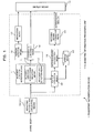
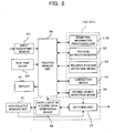
- FIGS. 1 and 2 illustrate a fingerprint authentication device (biometric information input device) as one embodiment of the invention and FIG. 1 is a block diagram illustrating a function configuration (principal configuration) of the device and FIG. 2 is a block diagram illustrating a detailed configuration thereof, where the same numerals are used to designate the same elements.
- biometric information primarily include a fingerprint, palm print, finger vein, palm vein, etc., and in this embodiment, a device using an image of fingerprint as biometric information will be explained.
- a fingerprint authentication device 1 has functions as biometric information collection means 10 and biometric information processing unit 110, and the biometric information processing unit 110 has functions as movement direction detection means 11, coordinate conversion means 14, position detection means 16, instruction means 17, feature extraction means 32, matching degree calculation means 19, matching degree determination means 20, biometric information central position detection means 21, and storage means 22.
- the fingerprint authentication device 1 of this embodiment is implemented by providing a sweep fingerprint sensor 31 as biometric information collection means 10 to a typical personal computer, etc. , that includes, for example, a real time clock 80, volatile memory unit 90, non-volatile memory unit 91 (storage means 22), display 81 (display means 15), and CPU (Central Processing Unit) 100.
- a typical personal computer etc.
- volatile memory unit 90 volatile memory unit 90
- non-volatile memory unit 91 storage means 22
- display 81 display means 15
- CPU Central Processing Unit
- biometric information processing unit 110 movesement direction detection means 11, coordinate conversion means 14, position detection means 16, instruction means 17, feature extraction means 32, matching degree calculation means 19, matching degree determination means 20
- feature extraction means 32 relative position detection means 33, correction means 34, moving object detection means 35, enrollment/matching data generating unit (generating means) 36, and matching unit (matching degree calculation means 19, matching degree determination means 20) 37
- predetermined program biometric information processing program
- the sweep fingerprint sensor 31 (biometric information collection means 10) is for visualizing biometric information of a subject to be authenticated and successively collecting a plurality of partial images (biometric information image) corresponding to the biometric information (fingerprint).
- the sensor operates so that the sensor causes a finger (living body site) of the subject to move relative to a collection surface (sensor surface) while contacting the surface and successively collects partial images of fingerprint of the finger, in order to read the living body site during relative movement of the site and successively collect a plurality of two-dimensionally arranged partial images related to the living body site as biometric information.
- the sweep fingerprint sensor 31 is also referred to as a fingerprint sensor 31 for simplification.
- a method for collecting a fingerprint image in the fingerprint sensor 31 may be implemented, for example, by any one of an electrostatic capacitance method, thermal sensing method, electric field method, and optical method.
- a fingerprint is formed on the skin (finger: living body site) of a subject to be authenticated and the print pattern of the fingerprint consists of ridges (contact part) partly brought into contact with the sensor surface and a valley (non-contacting part/gap part) kept out of contact with the sensor surface.
- the fingerprint sensor 31 utilizes a difference in its sensitivity to a ridge part in contact with the sensor surface and a valley part out of contact with the sensor surface and collects partial fingerprint images as a multilevel image.
- the multilevel image has different brightness varying depending on a distance from the sensor, i.e., typically, the ridge part closer to the sensor is displayed with a lower brightness and the valley part relatively farther from the sensor is displayed with a higher brightness.
- the subject moves his/her finger in an optional direction, for example, moves the finger from bottom side to fingertip side or from finger's right side to left side, while touching the sensor surface of the fingerprint sensor 31 with his/her finger.
- the device is provided with a mechanism for moving the fingerprint sensor 31 relative to a finger, the subject needs not to move his/her finger.
- the configuration of the fingerprint sensor 31 is well known in the art and therefore detailed explanation thereof is omitted.
- the real time clock 80 is used to add a time stamp to each of the partial images successively collected by the fingerprint sensor 31. Note that the real time clock 80 is not necessarily provided when a certain time interval in which images are acquired by the fingerprint sensor 31 is previously known and sufficiently constant so as to allow ignorance of an error in the time interval.
- the volatile memory unit 90 is for storing information such as partial images successively collected by the fingerprint sensor 31, characteristics, relative positions and post-correction results obtained by the function of the CPU 100, and various types of numerical values, needed to allow the CPU 100 to implement functions as a fingerprint authentication device of this embodiment.
- the non-volatile memory unit 91 is for retaining previously stored fingerprint data (enrollment data) related to the subject and functioning as the storage means 22 in FIG. 1.
- the fingerprint data retained in the non-volatile memory unit 91 could be the one extracted from a fingerprint image collected by the typical fingerprint sensor with a sensor surface larger than the size of a finger, or enrollment data generated by the enrollment/matching data generating unit 36 of this embodiment.
- the display 81 (display means 15) is for displaying a variety of images and information, functioning as biometric information display means displaying biometric information coordinate-converted by later-described coordinate conversion means 14, and further, displaying instruction given by the later-described instruction means 17 to a user (subject).
- the biometric information processing unit 110 is for processing partial fingerprint images (biometric information) collected by the fingerprint sensor 31 and has functions as movement direction detection means 11, coordinate conversion means 14, position detection means 16, instruction means 17, feature extraction means 32, matching degree calculation means 19, matching degree determination means 20, and biometric information central position detection means 21.
- the movement direction detection means 11 is for detecting a movement direction of a finger with respect to the fingerprint sensor 31, based on partial fingerprint images collected by the fingerprint sensor 31.
- the movement direction detection means 11 has functions as movement direction search range reduction means 12 and movement stop detection means 13.
- the movement direction search range reduction means 12 is for reducing a movement direction search range defined as a range over which a movement direction is detected by the movement direction detection means 11, from a previously set movement direction initial search range to a predetermined range including the detected movement direction, when the same movement direction has been successively detected by the movement direction detection means 11.
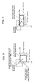
- FIGS. 3 and 4 are diagrams illustrating an example of a movement direction initial search range in the fingerprint authentication device 1 as one embodiment of the invention, wherein a partial fingerprint image (denoted by a dashed line) detected at time T- ⁇ T by the fingerprint sensor 31 and the partial fingerprint image (denoted by a solid line) detected after time AT has elapsed since then (at time T) are illustrated, respectively, along with the movement direction initial search range (denoted by a chain line) at time T.
- FIG. 3 and FIG. 4 are used to explain a range over which one of the two fingerprint image is moved so that a position with which the one fingerprint image is caused to overlap is moved little by little in order to find a position in which two fingerprint images corresponding to the same site just overlap with each other, and in particular, to indicate the movement direction initial search range.
- an arrow drawn from the center of the biometric information image collected at time T- ⁇ T to the center of the biometric information image collected at time T represents a movement direction.
- FIG. 3 illustrates an example in which the movement direction initial search range is in all directions (360 degrees) and centered on the fingerprint image (square in shape) collected by the fingerprint sensor 31.
- the fingerprint sensor 31 is substantially square in shape and the initial search range is set to 360 degrees when a movement direction of a finger is not determined in an initial state.
- a maximum range for the movement direction initial search range is Sx-Oxmin and Sy-Oymin in x-axis and y-axis directions, respectively.
- Sy and Sx indicate sizes of the partial fingerprint images in x-axis and y-axis directions, respectively, when horizontal direction and vertical direction axes are defined as x-axis and y-axis, respectively, for the partial fingerprint image.
- Oymin and Oxmin indicate sizes of a minimum necessary area in y-axis and x-axis directions, respectively, which area allows the sensor to determine that corresponding images overlap with each other.
- FIG. 4 illustrates an example in which the movement direction initial search range is in a minor axis direction (up/down direction in FIG. 4) and centered on the fingerprint image (rectangle in shape) collected by the fingerprint sensor 31.
- the initial search range is set to the up/down direction with respect to the partial fingerprint image and cascade directions with respect to the same.
- a positional relationship between the respective images in FIGS. 3 and 4 reflects a positional relationship between the finger of a subject to be authenticated and the fingerprint sensor 31 during the elapsed time AT between collection times corresponding to the partial fingerprint images.
- the positional relationship represents a situation in which fingerprint images are successively acquired when a finger is caused to slide on the fingerprint sensor 31. That is, since a relative position of the finger and the fingerprint sensor 31 changes from time to time, the fingerprint images collected at times T- ⁇ T and T, respectively, are the ones depicting finger parts that are slightly displaced from one another.
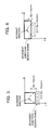
- FIGS. 5 and 6 each are diagrams illustrating another example of a movement direction initial search range in the fingerprint authentication device 1 as one embodiment of the invention and indicate situations in which the movement direction initial search ranges shown in FIGS. 5 and 6, respectively, are reduced (limited) to the downward direction. Note that in FIGS. 5 and 6, illustration of the biometric information image collected at time T- ⁇ T is omitted.
- a movement direction initial search range is set up (step A10) .
- the movement direction initial search range is previously set up based on the slide direction in which the subject potentially slides his/her finger with respect to the fingerprint sensor 31 and determined depending on, for example, how this fingerprint authentication device 1 is used and positions to which the fingerprint sensor 31 is attached. Note that when the slide direction on the fingerprint sensor 31 is not determined, it is desirable to set up a wide movement direction initial search range, as shown in FIGS. 3 and 4.
- step A30 whether or not the movement direction search range has been reduced is determined. In more detail, whether or not a flag indicating that the movement direction search range has been reduced is set to ON will be determined in later described step A90.
- a movement direction is searched within the initial search range (step A60).
- step A70 regarding a plurality of partial images successively collected by the fingerprint sensor 31, whether or not the movement directions are successively the same, i.e. , whether or not a finger moves in the same direction with respect to the fingerprint sensor 31 is examined, and simultaneously, whether or not the degree of overlap is above a predetermined threshold is determined (step A70 ) .
- the degree of overlap implies the degree of correlation or the degree of matching.
- the threshold used in step A70 will be explained.
- a subpixel error is present, images cannot be completely overlapped with each other and therefore the degree of overlap is affected and its value is reduced.
- a fingerprint represents projections and depressions, i.e., ridges and valleys on a finger skin and the finger skin is soft, pressing a finger against the sensor causes some distortion.
- the fingerprint image is read during pressing of a finger against the sensor, the distortion continuously changes.
- the degree of overlap is affected also when the distortion occurs and its value is reduced.
- Various other factors cause the degree of overlap to decrease and therefore the extent to which the degree of overlap is reduced is experimentally and analytically determined and then the threshold is determined.
- the subpixel error is an error of less than one pixel in a movement distance, caused by the quantization error of an image.
- biometric information is digitized when the information is converted to an image, the digitizing in practice causes successive information to be quantized into discrete information. In more detail, for example, when an image represented by pixels spaced at a pitch of 50 micrometers and a movement distance an object is less than 50 micrometers, the amount of movement is in practice below one pixel.
- one image that is caused to overlap the other is moved only in units of pixels and therefore a movement distance less than one pixel becomes equal to either one pixel or zero pixel.
- the distance is in practice determined to be one pixel rather than 0.6 pixels. In this case, an error of 0.4 pixel occurs and such an error is referred to as a subpixel error.
- step A80 when the movement direction is kept unchanged and the degree of overlap is not less than the threshold (refer to YES route at step A70), whether or not a condition shown in step A70 has been satisfied consecutively N times or more is determined (step A80).
- the movement direction search range reduction means 12 reduces (limits) the movement direction search range to a predetermined range including its movement direction (step A90), and further sets a flag indicating that the movement direction search range has been reduced to ON.
- step A70 when a finger is not moving in the same direction with respect to the fingerprint sensor 31 or the degree of overlap is less than the predetermined threshold (refer to NO route at step A70), or when the condition shown in step A70 has not been satisfied consecutively N times or more (refer to NO route at step A80 ) , the process returns to step A20.
- step A40 a movement direction is searched within the reduced movement direction search range (step A40) and further the movement direction search range is updated so that the range becomes a predetermined range including the movement direction searched in step A40 (step A50).
- step A100 whether or not any more partial fingerprint image collected by the fingerprint sensor 31 is present, or whether or not finger movement is stopped is determined.
- the process is terminated. Further, when the partial fingerprint image collected by the fingerprint sensor 31 is present or the finger movement is not stopped (refer to NO route at step A100) , the process returns to step A20.
- slide speed detectable by this fingerprint authentication device 1 is calculated using the following mathematical relationship (1) in reference to coordinate system used to express a fingerprint image.
- Vy and Vx are the y-axis direction component and x-axis direction component of the slide speed, respectively, and R is a pixel pitch. Note that although expanding/contracting distortion and/or skew distortion appears on the partial fingerprint image depending on the slide speed, the above relationship is assumed to be valid in an ideal condition free from such distortions.
- Vy and Vx vary depending on the features of a living body to be input and AT varies depending on the performance of the fingerprint sensor 31 and significantly affects determination of specification of the sensor. For example, when the performance of the fingerprint sensor 31 is already fixed and further when Sy and Sx are already determined, Oymin and Oxmin will be experimentally determined.
- the upper limit of a detectable slide speed shown in the above relationship (1) is represented by Vy and Vx.
- the performance of the fingerprint sensor 31 is such that the lower limit of ⁇ T is 3 msec, Oymin is 4 pixels, Sy is 16 pixels, R is 0.05 mm/pixel, and the partial fingerprint image ideally contains no distortion, the upper limit of the slide speed becomes 200 mm/sec.
- the movement direction detection means 11 has to operate following the slide speed of a living body and detect movement directions from hundreds of partial images per second, thereby putting a heavy load on the means.
- the movement direction detection means 11 utilizes inertia in order to efficiently calculate the slide direction and then achieve reduction in load imposed thereon.
- the detection means determines that the slide direction corresponds to either one of a positive direction or a negative direction along y-axis and after that, limits a search area only within a range including the determined direction in order to detect the slide direction.
- a living body or the fingerprint authentication device 1 moving at a speed of 200 mm/sec as the upper limit speed in the slide direction suddenly moves in the opposite direction after 0.003 msec has elapsed.
- a condition for determining stability of movement direction used as an example in the case shown in FIG. 7, is such that the movement direction is kept unchanged and the degree of overlap is above a predetermined threshold (see step A70).
- the movement direction search range it can be assumed, based on the law of inertia after stabilization of the slide direction, that a finger movement does not suddenly change its direction. Accordingly, for example, the movement direction search range is reduced to a range of the movement direction ⁇ a. Note that the search range may be generally either one of upper/lower and left/right areas.
- the movement stop detection means 13 is for detecting a stop of movement of a finger (living body site) on the fingerprint sensor 31.
- the fingerprint authentication device 1 operates so that when the movement stop detection means 13 has detected the stop of the finger movement of a subject to be authenticated, input of the corresponding partial image is stopped.
- the movement direction search range reduction means 12 reduces or divides up the search range in order to reduce the amount of calculations required for detection of movement direction, monitoring the stop of movement is necessary.
- the fingerprint sensor 31 is a sensor of the type allowing reading of the image (partial image: biometric information) of a fingerprint in the state of subject's finger being in contact with a sensor unit (not shown) and further when the finger becomes deformed due to friction, etc., a site contacting the sensor unit is, in some cases, hardly moved even if the finger moves.
- a site contacting the sensor unit is, in some cases, hardly moved even if the finger moves.
- monitoring the stop of the movement of living body is needed to collect the partial fingerprint image in a condition free from the influence of such pulling force (adhesion).
- FIG. 9 is a diagram illustrating an example of how the slide speed of a finger changes during collection of the fingerprint image in the fingerprint sensor 31, in which a solid line indicates the case where a finger smoothly slides and a dashed line indicates the case where pulling force between the finger and fingerprint sensor 31 is created.
- the slide speed smoothly changes and the case where the slide speed largely changes for the fingerprint sensor 31 to collect the fingerprint image. If it can be assumed the slide speed changes smoothly, the movement direction search range is limited to achieve reduction in processing time and prevent erroneous detection. However, deformation of a fingertip or the like occurs due to friction or adhesion with the sensor, the slide speed of a site contacting the sensor temporarily and instantly becomes zero, as denoted by a dashed line in FIG. 9, even if the living body itself is moving while maintaining a constant speed.
- the fingerprint authentication device 1 is configured so that a movement speed estimate range is provided so as to set up a stop monitoring range.
- step A90 movement direction search range reduction step
- speed is estimated using a change in the amount of movement or a change in the slide speed after stabilization of movement direction and the movement direction search range is reduced.
- V slide speed
- the slide speed V is apparently calculated using an imaging time interval I(K) and a relative position Pr(K) for a partial image, according to the following equation (2).
- V ( K ) Pr ( K ) / I ( K )
- the imaging time interval I(K) means a period of time from when imaging of a certain partial image is initiated to imaging of a subsequent partial image is initiated.
- the search range is considered less than one ridge width, allowing further reduction in the number of computations and reduction in the probability of danger of erroneous detection of the relative position.
- This estimating method becomes effective when it can be assumed that a change in the slide speed is very slow and the speed is constant.
- the relative position Pr'(K) may be estimated as in the following equation (5).
- P r ′ ( K ) Pr ( K ⁇ 1 ) + [ Pr ( K ⁇ 1 ) ⁇ Pr ( K ⁇ 2 ) ]
- the above equation (5) is useful when a speed change [Pr(K-1)-Pr(K-2)], i.e., acceleration can be assumed constant.
- a speed change [Pr(K-1)-Pr(K-2)]
- acceleration can be assumed constant.
- application of the equation (5) to the case where the slide speed changes so that the speed gradually increases during slide initiation allows the search range to be appropriately set up.
- the imaging time interval I(K) cannot be considered constant
- adding a speed change based on a concept similar to the above mentioned concept allows the search range to be appropriately set up.
- FIG. 10 is a diagram illustrating an example of a stop monitoring range and movement direction initial search range in the fingerprint authentication device 1 as one embodiment of the invention, in which the partial image (denoted by a dashed line) of a fingerprint detected at time T- ⁇ T by the fingerprint sensor 31 and the partial image (denoted by a solid line) of a fingerprint detected after time ⁇ T has elapsed (at time T) are shown along with the movement direction initial search range (denoted by a chain line) and stop monitoring range at time T.
- the stop monitoring range and movement direction search range are drawn by superimposing the speed estimate range and stop monitoring range related to the slide speed shown in FIG. 9 on the biometric information image collected at time T- ⁇ T.
- Detection of the slide speed takes longer period of time as the search range becomes wider. Accordingly, utilizing the fact that the slide speed can be predicted to some extent based on its latest speed value effectively limits the search range to a narrower range.
- the fingerprint authentication device 1 is configured so that in order to be able to properly detect the movement direction and movement distance of a living body even when the slide speed has suddenly changed to zero, the living body is assumed to be only slightly displaced to a range from a reference position (at the time point shown in the figure) referred to when the movement distance is detected, and then, the range to which the living body is slightly displaced is included in the search range.
- the range slightly displaced from the reference position is referred to as a stop monitoring range.
- step number indicates the same or nearly the same processing and therefore detailed explanation thereof is omitted.
- the movement direction search range is reduced (refer to YES route at step A30 )
- the movement direction is searched within the reduced movement direction search range (reduced search range) (step A40) and a matching degree (maximum matching degree) MAX_Cv representing the degree of overlap of corresponding images within the movement speed estimate range is calculated and stored in the non-volatile memory unit 90, etc. (step A51).
- the matching degree is the degree to which two successive partial images out of a plurality of partial images collected by the fingerprint sensor 31 match each other.
- one or more of partial images are skipped until the movement distance reaches a predetermined number of pixels or more. For example, when the movement distance reaches in practice only 0.5 pixels, skipping one partial image allows detection of one-pixel movement. Note that the movement speed at this point is 0.5 pixels on average.
- the movement speed estimate range is updated (step A52) and the movement speed is searched within the stop monitoring range (step A53). Further, the matching degree (maximum matching degree) MAX_Cs representing the degree of overlap of corresponding images in the stop monitoring range is calculated and stored in the volatile memory unit 90, etc. (step A54).
- MAX_Cv and MAX_Cs are compared (step A55) and when MAX_Cs is greater (refer to NO route at step A55), a finger is determined to be in a stop state and the stop monitoring count M is incremented (step A56). Further, when MAX_Cv is greater (refer to YES route at step A55), a finger is determined to be in a movement state and the stop monitoring count M is set to zero (step A57).
- the stop monitoring count M is a counter used for determination of continuation of a stop state and when the stop state continues for a long period of time, i.e., the value of the stop monitoring count M is beyond a threshold T, termination of input of biometric information is determined, and when a finger is temporarily in the stop state, detection of the movement direction is continued.
- step A100 whether the stop monitoring count M is beyond the threshold T or biometric information image is not present is determined (step A100 ) and when the biometric information image is not present or the stop monitoring count M is beyond the threshold T (refer to YES route at step A100), termination of collection of the partial image of a fingerprint is determined and the process is terminated. Further, when the biometric information image is present or the stop monitoring count M is below the threshold T (refer to NO route at step A100), the process returns to step A20.
- the count M is used to determine the fact that the stop state has continued for a long period of time and determination is performed based on the count number in the count
- the invention is not limited to the above example, but for example, may be configured so that the duration of continuation of a stop state is measured and the duration is compared to a threshold. In this manner, various modifications may be made without departing from the scope of the invention.
- a coordinate conversion means 14 is for using the movement direction detected by a movement direction detection means 11 and performing a coordinate conversion on biometric information collected by the fingerprint sensor 31. Further, the coordinate conversion means 14 is operable to use information indicative of a difference between the movement direction detected by the movement direction detection means 11 and a predetermined direction related to the fingerprint sensor 31 for coordinate conversion.
- biometric information collected by the fingerprint sensor 31 includes not only a fingerprint image (partial image) collected by the fingerprint sensor 31 but also a variety of information derived from the fingerprint image, for example, minutiae information extracted from the fingerprint image. Accordingly, the coordinate conversion means 14 may perform a coordinate conversion on the minutiae information extracted from the fingerprint image. Note that in this embodiment, an example in which a partial fingerprint image is used as biometric information and the coordinate conversion means 14 perform a coordinate conversion on the partial image will be shown.
- the coordinate conversion means 14 uses the movement direction detected by the movement direction detection means 11 for coordinate conversion of the partial fingerprint image collected by the fingerprint sensor 31.
- the coordinate conversion is performed using then affine conversion as shown in the following equation (6).
- an area up to the first joint of a finger is placed on the sensor surface to obtain the entire fingerprint image and the finger is caused to slide until the finger tip is brought into contact with a biometric information collection means 10.
- a biometric information collection means 10 For example, in the sweep fingerprint sensor, an area up to the first joint of a finger is placed on the sensor surface to obtain the entire fingerprint image and the finger is caused to slide until the finger tip is brought into contact with a biometric information collection means 10.
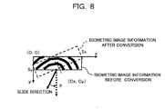
- FIG. 8 is a diagram illustrating a relationship between biometric information images before and after coordinate conversion in the fingerprint authentication device 1 as one embodiment of the invention.
- ⁇ is rotation angle
- Cx and Cy are rotation centers in x-axis and y-axis directions.
- the rotation angle ⁇ is represented by the following equations (8) to (11).
- first quadrant ) ⁇ ⁇ 4 ⁇ tan ⁇ 1 ( ⁇ y ⁇ x ) i i ) ⁇ x ⁇ 0 , ⁇ y > 0
- second quadrant ) ⁇ ⁇ ⁇ 4 ⁇ tan ⁇ 1 ( ⁇ y ⁇ x ) i i i ) ⁇ x ⁇ 0
- the processing of coordinate conversion generally takes a long period of time because conversion computation is made using a rotating matrix containing trigonometric functions as described above. Therefore, to avoid complexity, coordinate conversion taking into account only the sign of Vy may be employed as simpler coordinate conversion. That is, the conversion is performed in such a way that a y-axis component of the slide direction points in a vertical and downward direction with respect to the biometric information image.
- the biometric information image is rotated 180 degrees and then output.
- conversion is completed only by copying pixel values from one memory to another, allowing saving of memory capacity and reduction in computation time.
- angle information is not used in order to avoid overhead, except that only rotation angle information is added to the partial fingerprint image.
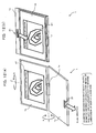
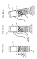
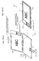
- FIGS. 12(a), 12(b) are diagrams illustrating the appearance of the fingerprint authentication device 1 as one embodiment of the invention and FIG. 12(a) is a diagram illustrating an example of the appearance of the fingerprint authentication device 1, and FIG. 12(b) is a diagram illustrating an example of the appearance of the fingerprint authentication device 1 after modification.
- the fingerprint authentication device 1 shown in FIGS. 12(a), 12(b) includes a main body 1 a provided with a fingerprint sensor 31 and a display unit 1b provided with a display 81, in which the main body and the display unit are connected together so that those two components are openable by way of a two-axis hinge (nail clipper designed hinge) 1c.
- the display unit 1b can be rotated nearly 180 degrees about an axis c1 of the two-axis hinge 1c relative to the main body 1a, thereby allowing the main body 1a and display unit 1b to be folded in a hinge-like manner. Further, as denoted by an arrow “b” in FIG. 12(a), the display unit 1b can be rotated about an axis c2 of the two-axis hinge 1c, thereby allowing the display unit 1b to be rotated 180 degrees.
- the display unit 1b in a state shown in FIG. 12(a) is rotated respectively about the axes c1 and c2 of the two-axis hinge 1c relative to the main body 1a, thereby allowing the main body 1a and display unit 1b to be folded in such a manner that the display 81 is exposed to a front of the device, as shown in FIG. 12(b).
- both the main body 1a and display unit 1b have a rectangle shape and the main body 1a has a larger dimension than the display unit 1b, along a direction orthogonal to the side thereof used to provide connection with the display unit 1b via the two-axis hinge 1c.
- the fingerprint sensor 31 is formed on an end portion of a surface of the main body 1a opposite to the two-axis hinge 1c, which surface is to overlap the display unit 1b.
- the fingerprint authentication device 1 can be incorporated into a laptop PC ⁇ having the fingerprint sensor 31 mounted on the main body 1a and tailored to rotate the display unit 1b by 180 degrees and then fold the same.
- the display 81 is mounted so that the orientation of the display 81 is kept unchanged in both cases as shown in FIG. 12(a) and in FIG. 12(b).
- FIG. 12(a) when the subject uses the fingerprint sensor 31 in the unfolded state of the main body 1a and display unit 1b (when using in an unfolded state), the subject slides his/her finger in the direction from the two-axis hinge 1c to the opposite end (front side) of the main body 1a, and as shown in FIG. 12(b) , when the subject uses the fingerprint sensor 31 in the folded state of the main body 1a and display unit 1b (when using in a folded state), the subject slides his/her finger in a direction from the opposite end of the main body 1a to the two-axis hinge 1c.
- the fingerprint sensor 31 is brought into a state in which the sensor is rotated 180 degrees when viewed from the subject.
- the coordinate conversion means 14 in the fingerprint authentication device 1 performs a coordinate conversion on the partial fingerprint image depending on the slide direction.
- the coordinate conversion means 14 performs a coordinate conversion as described above so that the partial fingerprint image collected by the fingerprint sensor 31 is rotated 180 degrees.
- an upright fingerprint image (partial image) is displayed on the display 81 even in the folded state, preventing the biometric information image from being reversed in the up/down or left/right direction and the subject from being confused.
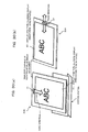
- FIGS. 13(a), 13(b) are diagrams to explain instruction directions displayed on the display 81 of the fingerprint authentication device 1 as one embodiment of the invention.
- a position detection means 16 is for detecting a position of the finger of the subject relative to the fingerprint sensor 31 and an instruction means 17 is for instructing and prompting the subject to move his/her finger, based on the subject's finger position detected by the fingerprint sensor 31, so that the subject's finger is disposed in a position in which the finger is to be placed on the fingerprint sensor 31. For example, an instruction for the subject to promptly move his/her finger is displayed on the display 81, along with a direction in which the finger is to be moved.
- the display 81 is mounted so that the orientation of the display 81 is kept unchanged when viewed from the subject, regardless of whether the device is used in the unfolded state of the main body 1a and display unit 1b as shown in FIG. 13(a) or in the folded state of the main body 1a and display unit 1b as shown in FIG. 13(b).
- the slide directions of a finger on the fingerprint sensor 31 in the unfolded state (shown in FIG. 13(a)) and in the folded state (shown in FIG. 13(b)) are opposite, the subject may simply slide his/her finger on the fingerprint sensor 31 with the same action (for example, towards him/herself) when inputting the fingerprint image.
- the slide direction and the vertical/downward direction on the display 81 match, the subject may be properly instructed.
- the coordinate conversion means 14 performs a coordinate conversion so that the partial fingerprint image collected by the fingerprint sensor 31 is reversed in the up/down or left/right direction.
- the instruction means 17 instructs the subject to slide his/her finger in the reversed up/down or left/right direction, based on the detected slide direction. Note that in the example shown in FIGS. 13(a), 13(b), a direction in which the subject should slide his/her finger is displayed as an arrow on the display 81 for the purpose of warning to the subject.
- the position detection means 16 is operable to detect an area containing biometric information from the image acquired by the fingerprint sensor 31. For example, when a living body to be subjected to this treatment is a fingerprint, the biometric information image expressed by a ridge having a larger pixel value than a valley is assumed. Further, when the biometric is hand vascular, palm vein or finger vein, the biometric information image expressed by a vein having a larger pixel value than a blood vessel other than a vein is assumed. Further, when the above relationship is opposite, brightness inversion techniques are applied to the image and then the same discussion holds true for the image.
- biometric information area the area containing the biometric information is referred to as a biometric information area.
- a general binary method or clustering method can be applied. There is a simplest method in which a predetermined threshold is defined as a certain pixel value and pixels having a value greater than the threshold are extracted as biometric information. Use of the gravity center and variance of the extracted pixels allows detection of the position of the biometric information area.
- the instruction means 17 performs instructions using difference information Dx, Dy indicative of differences between positions Bx, By detected by the position detection means 16 and the corresponding central positions Cx, Cy of the fingerprint sensor 31.
- the instruction means 17 instructs the subject to move the living body (finger) to the left.
- the instruction is done, for example, by displaying a mark indicating a direction as a left-pointing arrow, etc., on the display 81.
- directional instruction may be not displayed in a detailed fashion, but only one chosen out of constituent instruction directions and having a greater magnitude than the others is displayed, for example, using a step size of 90 degrees.
- a feature extraction means 32 is for extracting the features of each partial image and the positions of the features from each of a plurality of partial images collected by the fingerprint sensor 31.
- the features both the foreground of each partial image (value of brightness of a ridge image in the embodiment) and the edges of the foreground (value of brightness gradient in the embodiment) may be extracted or ridge end and bifurcation may be extracted from a pattern created by changing the foreground (e.g., ridge image) of each partial image to thin lines.
- a relative position detection means 33 is for detecting a relative position of two partial images based on the features (extracted by the feature extraction means 32) present in the area where two successive partial images out of a plurality of partial images collected by the fingerprint sensor 31 overlap with each other.
- the relative position detection means 33 may detect the above relative position with reference to one or more relative positions detected until the current detection is initiated, or may detect the above relative position with reference to a relative position that has been estimated based on one or more relative positions detected until the current detection is initiated and is to be subsequently detected.
- the relative position detection means 33 may be configured to group individual partial images successively collected by the fingerprint sensor 31 into two or more partial areas sharing a common area where these partial areas overlap with one another and then process these partial areas, and detect the above relative position for each of the two or more partial areas.
- a correction means 34 is for correcting image distortion due to detection delay in the fingerprint sensor 31 or distortion due to deformation of finger.
- the correction means 34 has the following two types of correction functions. According to the first correction function, the amount of feature distortion (amount of distortion due to finger deformation) is calculated based on the relative position detected by the relative position detection means 33 and the position of features of each partial image, and the position of features of each partial image is corrected based on the calculated amount of distortion.
- the position of features of each partial image is corrected so as to eliminate the distortion (expanding/contracting distortion and/or skew distortion) of each partial image due to delay in collection by the fingerprint sensor 31 based on a time interval for collection of each partial image by the fingerprint sensor 31, delay caused when the fingerprint sensor 31 collects each partial image, and the relative position detected by the relative position detection means 33, in order to acquire the relative position of features.
- the correction means 34 corrects the position of features so that the distortion of each partial image due to delay in collection by the fingerprint sensor 31 is eliminated.
- the correction means 34 needs to be provided when distortion occurs in an image collected by the fingerprint sensor 31 and the correction means 34 is not necessarily provided when the fingerprint sensor 31 is able to ignore the distortion of the image.
- a moving object detection means 35 is for detecting presence/absence of a moving object (in this case, subject's finger) moving relative to the fingerprint sensor 31 based on a plurality of partial images collected by the fingerprint sensor 31 and for example, is operable to calculate the weighted mean image of partial images that have been collected by the fingerprint sensor 31 until the current collection is initiated and detect presence/absence of the movement object based on the calculated weighted mean image.
- the moving object detection means 35 is operable to detect the existence of the movement object when the value of a difference between latest partial image collected by the fingerprint sensor 31 and the calculated weighted mean image exceeds a predetermined threshold, and the predetermined threshold is set to a value greater than the value of variation due to noise.
- An enrollment/matching data generating unit (generating means) 36 is for using the features extracted by the feature extraction means 32 and the relative position of features acquired by the correction means 34 and then generating fingerprint data (pre-stored data and matching data) used to identify, for authentication, a subject as the person himself/herself.
- fingerprint data known information such as positions and pattern of ridge bifurcation and end
- the fingerprint data generated by the enrollment/matching data generating unit 36 is enrolled and then stored as enrollment data in a non-volatile memory unit 91.
- the fingerprint data information about ridge bifurcation and end
- the enrollment/matching data generating unit 36 is sent as matching data to a matching unit 37.
- the matching unit (matching means) 37 is for comparing the matching data generated by the enrollment/matching data generating unit 36 and the subject's enrollment data registered in non-volatile memory unit 91 in order to perform matching and then identify, for authentication, a subject as the person himself/herself.
- the matching unit 37 is configured so that the features and relative position obtained from partial images visualized at earlier time points (time points recorded as a time stamp value by a real time clock 80) by the fingerprint sensor 31 are preferentially used to perform the above matching which is completed upon confirmation of matching results for the subject.
- the matching unit 35 comprises a matching degree calculation means 19 and matching degree determination means 20.
- the matching degree calculation means 19 is for calculating the degree of matching between the matching data generated by the enrollment/matching data generating unit 36 and the subject's enrollment data stored in the non-volatile memory unit 91. Note that for example, a correlation coefficient in a cross-correlation method is used as the degree of matching.
- the matching degree determination means 20 is operable to determine, based on the degree of matching calculated by the matching degree calculation means 19, that the matching data generated by the enrollment/matching data generating unit 36 and the subject's enrollment data stored in the non-volatile memory unit 91 match, for example, when the degree of matching is greater than a previously defined threshold, in order to identify, for authentication, the subject as a person for whom corresponding biometric data has already been registered (enrolled).
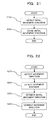
- FIG. 14 is a flow chart (steps C10 to C40) for explanation of how the enrollment data is enrolled in the fingerprint authentication device 1 as one embodiment of the invention
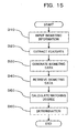
- FIG. 15 is a flow chart (steps D10 to D60) for explanation of how the matching is performed
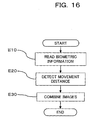
- FIG. 16 is a flow chart (steps E10-E30) for explanation of how steps of inputting biometric information are performed in FIGS. 14 and 15.
- a subject uses the biometric information collection means 10 (fingerprint sensor 31) to perform input of biometric information (fingerprint) (step C10).
- a feature extraction unit 32 performs extraction of characteristics based on biometric information input through the fingerprint sensor 31 (step C20) and the enrollment/matching data generating unit 36 generates biometric data (step C30), and the generated biometric data is recorded in the non-volatile memory 91 (storage means 22) (step C40).
- biometric information is done using the biometric information collection means 10 (fingerprint sensor 31) (step D10).
- the feature extraction unit 32 performs extraction of features based on the biometric information input through the fingerprint sensor 31 (step D20) in order to generate biometric data (step D30).
- the matching degree calculation means 19 retrieves the biometric data stored in the non-volatile memory 91 (storage means 22) (step D40) in order to perform calculation of the degree of matching (step D50) and the matching degree determination means 20 performs determination based on the calculated degree of matching (step D60).
- step E10 of FIG. 14 and step D10 of FIG. 15 is done in accordance with the flow chart shown in FIG. 16. That is, after the partial image of a living body site has been read by the biometric information collection means 10 (step E10), detection of movement distance is performed based on the collected biometric information (step E20), after which partial images are combined (step E30).
- a movement distance detection step denoted as step E20 may be initiated after a biometric information reading step, denoted as step E10, has been repeatedly performed on a plurality of partial images, or an image combining step denoted as step E30 may be initiated after the biometric information reading step denoted as step E10 and movement distance detection step denoted as step E20 have been repeatedly performed, or alternatively, the biometric information reading step denoted as step E10, movement distance detection step denoted as step E20 and image combining step denoted as step E30 may be repeatedly performed, meaning that various modifications may be made within ⁇ the scope of the invention.
- determination of such loop termination can be performed using combination of optional elements such as elapsed time, the number of readings, movement distance, movement stop, available buffer capacity, and the fact that an image has no contents. Note that the determination of loop termination using the movement distance out of these elements can be performed after detection of movement distance.
- step C10 of FIG. 14 and step D10 of FIG. 15 corresponds to the biometric information input steps denoted as step C10 of FIG. 14 and step D10 of FIG. 15, and further to the biometric information reading step denoted as step E10 and movement distance detection step denoted as step E20 of FIG. 16.
- the coordinate conversion means 14 performs a coordinate conversion on the collected biometric information based on the movement direction from the biometric information detected by the movement direction detection means 11, even when an angular difference (rotational displacement) between the most preferable slide direction on the fingerprint sensor 31 (e.g., normal line direction passing through the center of the fingerprint sensor 31) and the slide direction of subject's finger occurs during collection of partial images of a fingerprint, the rotational displacement can be corrected, allowing an upright image to be reliably obtained.
- This allows biometric data to be captured successfully even when the slide direction changes each time a finger slides and rotational displacement is present in each of individual partial images of a fingerprint. That is, it becomes possible for the device to be insensitive to influence of the rotational displacement present in the fingerprint image, which displacement changes depending on the slide direction.
- a fingerprint image is correctly oriented (an upright image) even if the partial image of a fingerprint is collected when the orientation of the fingerprint sensor 31 is changed, e.g., the fingerprint authentication device 1 is rotated to an upside down position and then used, and the fingerprint image can be collected irrespective of the orientation of the fingerprint authentication device 1 (fingerprint sensor 31), thereby allowing the device to be highly convenient.
- the fingerprint image can be obtained as an upright image regardless of the pointing direction (orientation) of the fingerprint authentication device 1 , display 81, and fingerprint sensor 31 etc., and therefore there is no need for detecting and determining the pointing direction (orientation) of the fingerprint authentication device 1, display 81, and fingerprint sensor 31, etc., thereby eliminating the need for inclusion of functions (hardware, software) to detect and determine such a pointing direction and reducing manufacturing cost.
- the device is able to display the biometric information image so that the image is never affected by rotation of the device, thereby easily providing visual confirmation that the fingerprint image has been properly obtained.
- the biometric information collection means 10 there is an increase in the degree of freedom of direction of the sensor (fingerprint sensor, etc.) providing the biometric information collection means 10, allowing flexible mounting of the sensor and reduction in the area required for a wiring pattern, reducing the size and price of the device.
- FIGS. 17(a), 17(b) are diagrams to explain a relationship between a wiring pattern and the mounting area of the pattern on the fingerprint sensor 31,
- FIG. 17(a) is a diagram illustrating the mounting area in the case of the wiring pattern length being short
- FIG. 17(b) is a diagram illustrating the mounting area in the case of the wiring pattern length being long.
- the degree of freedom of mounting the sensor can be made high and the sensor can be connected using short wires when mounting of the fingerprint sensor 31 is performed, the mounting area can be reduced.
- the biometric information collection means 10 is a device of the type allowing biometric information to be read by the biometric information collection means 10 being brought into contact with a living body and further when the living body is moving relative to the sensor and a living body site contacting the sensor only intermittently moves due to bending of outer skin of the living body due to friction etc., in other words, pulling force occurs between the sensor and living body, a movement direction of the living body can be properly detected, allowing reliable collection of biometric information.
- the device allows a display means 15 to display biometric information (upright image) after correction of the rotational displacement of information.
- biometric information upright image
- the device allows the display means 15 to display an upright image and further allows a high degree of freedom of the mounting direction of the sensor providing the biometric information collection means 10.
- the device is able to easily perform instruction, providing great convenience.
- the degree of freedom of the using direction of the biometric information collection means 10 is high, e.g., when the means 10 is used in an upside down position, the device is able to properly instruct the subject to correct positional displacement and further allows the high degree of freedom of the mounting direction of the sensor providing the biometric information collection means 10.
- performing authentication using biometric information after correction of rotational displacement of the information allows authentication process to be performed without influence of rotational displacement during collection of biometric information. For example, even when the orientation of the fingerprint authentication device during registration of enrollment data and the orientation of the fingerprint authentication device during matching are significantly different, the device is able to perform authentication without lowering its authentication ability, thereby providing great convenience.
- FIG. 18 is a, block diagram illustrating the functional configuration of a first modification of the fingerprint authentication device as one embodiment of the invention.
- a fingerprint authentication device 101 is configured in nearly the same way as in the first embodiment, except that a biometric information central position detection means 21 is provided instead of the position detection means 16 in the fingerprint authentication device 1 of the first embodiment. Note that in FIG. 18, the same numerals previously used designate the same or nearly the same elements and therefore detailed explanation thereof is omitted.
- the biometric information central position detection means 21 is for detecting a central position of a partial fingerprint image (biometric information) collected by the fingerprint sensor 31 (biometric information collection means 10). Note that as a method for detecting the central position of partial image through the use of the biometric information central position detection means 21, a variety of methods previously described can be employed and for example, when the biometric information is a fingerprint, the technology disclosed in Japanese Patent Laid-Open No. 2002-109543) can be employed.
- the instruction means 17 of the first modification is for correcting difference information indicative of a difference between a biometric information central position detected by the biometric information central position detection means 21 and a predetermined position on the fingerprint sensor 31, using difference information indicative of a difference between a movement direction detected by the movement direction detection means 11 and a predetermined direction, and instructing and prompting the subject to move his/her finger so that the subject's finger is located in place on the fingerprint sensor 31.
- the instruction means 17 instructs (guides) the subject to move his/her finger to the left.
- the instruction to the subject may be done, for example, by displaying a mark indicating a direction as a left-pointing arrow, etc., on the display 81.
- directional instruction is not displayed in a detailed fashion, but only one chosen out of constituent instruction directions and having a greater magnitude than the others is displayed, for example, using a step size of 90 degrees.
- the fingerprint authentication device 101 As described above, according to the fingerprint authentication device 101 as the first modification of the invention, action and effect similar to those of the first embodiment are obtained and in addition, an effect that authentication can be performed without influence of the rotational displacement is obtained by allowing the device to perform authentication using biometric information in which a rotational displacement has been corrected. Further, even when the degree of freedom of the using direction of the fingerprint sensor 31 is high, e.g., when the sensor is used in an upside down position, the device is able to properly instruct a user to correct a positional displacement and in addition, the degree of freedom of the mounting direction of the fingerprint sensor 31 becomes high, allowing the device to be extremely practical for use.
- the fingerprint sensor 31 For an information processing device provided with the above-described fingerprint sensor 31 and display 81, it is possible - to move a cursor (pointer) displayed on the display 81 using the fingerprint sensor 31. That is, the fingerprint sensor 31 is allowed to function as a pointing device.
- FIG. 19 is a block diagram illustrating the functional configuration of a second modification of the fingerprint authentication device as one embodiment of the invention.
- a fingerprint authentication device 102 of the second modification includes the biometric information collection means 10, the movement direction detection means 11, the coordinate conversion means 14, the display means 15, the storage means 22, the biometric information movement direction correction means 40 (reference direction setting means 41), a movement distance detection means 42, and a pointer movement control means 43.
- the same numerals previously used designate the same or nearly the same elements and therefore detailed explanation thereof is omitted.
- the movement distance detection means 42 is for detecting the movement distance of subject's (user's) finger with respect to the fingerprint sensor 31, i.e., detecting a movement distance of biometric information.
- the reference direction setting means 41 is for setting up the reference direction to which the movement direction of user's finger on the fingerprint sensor 31 refers and the pointer movement control means 43 is for controlling the movement of a pointer on the display means 15 based on the reference direction set up by the reference direction setting means 41, the movement direction of a finger detected by the movement direction detection means 11, and the movement distance of a finger detected by the movement distance detection means 42.
- the biometric information movement direction correction means 40 includes the reference direction setting means 41 and is for detecting and correcting the movement direction of a finger with reference to the reference direction set up by the reference direction setting means 41.
- Displayed on the display means 15 is a cursor that moves in response to a finger moving distance and the direction on the fingerprint sensor 31.
- FIGS. 20(a), 20(b) are diagrams illustrating examples of appearance of the second modification of the fingerprint authentication device 1 as one embodiment of the invention
- FIG. 20(a) is a diagram illustrating an example of appearance of the fingerprint authentication device 102 before modification
- FIG. 20(b) is a diagram illustrating an example of appearance of the fingerprint authentication device 1 after modification.
- the fingerprint authentication device 102 shown in FIGS. 20(a), 20(b) also includes the main body 1a provided with the fingerprint sensor 31 and the display unit 1b provided with the display 81, in which the main body and the display unit are openably connected together through the two-axis hinge (nail clipper hinge) 1c.
- the fingerprint authentication device 102 is incorporated in a laptop personal computer having the fingerprint sensor 31 mounted on the main body 1a and tailored to rotate the display unit 1b by 180 degrees and then fold the same.
- the display 81 is mounted so that the direction of the display 81 is kept unchanged, regardless of whether the device is used as shown in FIG. 20(a) or as shown in FIG. 20(b).
- the subject since in the fingerprint authentication device 102, the subject (user) slides, during fingerprint authentication, his/her finger on the fingerprint sensor 31 so that the finger is pulled back towards the user, when the slide direction matches the vertical/downward direction relative to the display 81, the subject will be able to correct the movement direction of a finger.
- the device may be configured so that after the coordinate conversion means 14 performs coordinate conversion on the biometric information image such that the biometric information image is reversed in the up/down or left/right direction based on the slide direction, the device determines the movement direction and movement distance. Or, when the device does not use the biometric information image, the device may convert the detected movement direction rather than the biometric information image.
- the fingerprint authentication device 102 is configured so that in order to properly detect the movement direction, the movement direction of a finger on the fingerprint sensor 31 is previously input as a reference direction by the reference direction setting means 41 and stored as a reference value (initial value) to previously correct the movement direction in the storage means 22 (initial value setting step), and the movement direction is corrected using the set reference value (correction step).
- FIG. 21 is a flow chart (steps F10 to F20) for explanation of details of the initial value setting step
- FIG. 22 is a flow chart (steps G10 to G40) for explanation of details of the movement direction correction step.
- the movement direction input as a reference direction is detected by the movement direction detection means 11 (step F10), and then the detected movement direction is stored as an initial value (initial direction) in the storage means 22 (step F20), and the process is terminated.
- the movement direction is detected by the movement direction detection means 11 (step G10) and the movement distance is detected by the movement distance detection means 42 (step G20). Note that the movement direction detection step and movement distance detection step may be reversed in order or performed simultaneously.
- the biometric information movement direction correction means 40 retrieves the initial value (initial direction) stored in step F20 of the initial value setting step from the storage means 22 (step G30) in order to calculate a difference between the movement direction detected in step G10 and the initial direction for correction of the movement direction (step G40).
- the pointer movement control unit 43 controls a pointer so that it is moved on the display in the corrected movement direction.
- the reference direction corresponding to the movement direction of a living body site is previously set up as an initial value and the movement direction of the living body site is corrected using the initial value to allow the biometric information collection means 10 to be used in various directions, and even when the degree of freedom of the using direction of the biometric information collection means 10 is high, the device is able to properly detect the movement direction of the living body site and to increase the degree of freedom of the mounting direction of the sensor providing the biometric information collection means 10 .
- the pointer can be moved on the display 81 in the direction input by the user.
- the device of the invention is not limited to the configuration of FIG. 19, but may include all of or at least a portion of the above components and allow the corresponding components to function individually.
- FIGS. 23(a), 23(b), 23(c) are diagrams illustrating examples in which the fingerprint authentication device of the invention is applied to a mobile device (mobile phone) 200 provided with a sweep fingerprint sensor and FIGS. 24 (a), 24(b) are diagrams illustrating examples of fingerprint images derived from images collected in the states of FIGS. 23(b), 23(c).
- the mobile device 200 shown in FIGS. 23(a) to 23(c) incorporates a sweep fingerprint sensor 31 therein for the purpose of inclusion of functions such as owner authentication.
- a mobile device such as a recent mobile phone is reduced in volume, how a user holds the device changes in various forms. Particularly, since the user holds the mobile phone by one hand, how the user holds the phone is considered to easily change.
- the user may be unfamiliar with sliding ⁇ his/her finger on the sensor, but having tried matching several times, the user becomes familiar with sliding and in some cases, changes his/her way of holding the phone.
- FIGS. 23 (a) , 23 (b) illustrate examples in which a rotational displacement around the normal to a paper is present.
- a rotational displacement between enrollment data and input data is present, authentication ability is reduced, according to the invention, a fingerprint image is coordinate-converted so that the slide direction points downward and therefore authentication can be performed without a rotational displacement, as shown in FIGS. 24(a), 24(b).
- the rotational displacement may be corrected by coordinate converting the fingerprint image or by coordinate converting the enrollment data or matching data.
- the display direction of images corresponding to the enrollment data and input data becomes independent of the slide direction when the fingerprint image is displayed.
- FIGS. 25(a), 25(b) are diagrams illustrating examples in which the fingerprint authentication device of the invention is applied to a mobile device (PDA: Portable Digital Assistant ) provided with a sweep fingerprint sensor and a PDA 201 shown in FIGS. 25(a), 25(b) incorporates thereon the sweep fingerprint sensor 31 that is disposed in the vertical direction (90 degrees or 270 degrees).
- PDA Portable Digital Assistant
- the slide direction expected in the PDA 201 is the horizontal direction and a user (subject) is able to input his/her fingerprint using either his/her right or left hand.
- FIGS. 26(a), 26(b) are diagrams illustrating examples in which the fingerprint authentication device of the invention is applied to a mobile device (PDA) provided with a sweep fingerprint sensor and the configuration of the PDA 202 shown in FIGS. 26(a) , 26(b) is similar to that after 90-degree rotation of the PDA 201 shown in FIGS. 25 (a), 25(b), and the PDA 202 is usable even after its 180-degree rotation.
- PDA mobile device
- the PDA 202 allows a user to input his/her fingerprint irrespective of whether the device is rotated 180 degrees.
- FIGS. 27(a), 27(b) are diagrams illustrating examples in which the fingerprint authentication device of the invention is applied to a mobile device (PDA) provided with a sweep fingerprint sensor.
- PDA mobile device
- a PDA 203 shown in FIGS. 27(a), 27(b) incorporates thereon the sweep fingerprint sensor that is disposed on a surface opposing the surface on which the display 81 of a main body 203a is formed. The sensor is mounted in the vertical direction (90 degrees or 270 degrees).
- the slide direction expected in the PDA 203 is the horizontal direction and a user (subject) is able to input his/her fingerprint using either his/her right or left hand.
- FIGS. 28(a), 28(b) are diagrams illustrating examples in which the fingerprint authentication device of the invention is applied to a mobile device (laptop PC (Personal Computer)) provided with a sweep fingerprint sensor and FIG. 28(a) is a diagram illustrating a display unit 204b in an unfolded state, and FIG. 28(b) is a diagram illustrating a display unit 204b as a front unit in a folded state.
- a mobile device laptop PC (Personal Computer)
- FIG. 28(b) is a diagram illustrating a display unit 204b as a front unit in a folded state.
- the laptop PC 204 shown in FIGS. 28(a), 28(b) incorporates thereon the sweep fingerprint sensor 31 adjacent to the display 81 of the display unit 204b in the horizontal direction, and further, similarly to the fingerprint authentication device 1 shown in FIG. 12, a main body 204a and the display unit 204b provided with the display 81 are openably connected together through a two-axis hinge (nail clipper hinge) 204c.
- the display unit 204b of the laptop PC 204 is rotated about an axis "b" of the two-axis hinge 204c and further folded through an axis "a", and when the display unit is folded so as to allow the display 81 to serve as a front of the PC, a screen to be displayed on the display 81 is displayed in such a manner that the screen is rotated 180 degrees.
- the invention allows a user to input his/her fingerprint independent of 180-degree rotation of the device.
- the display ⁇ orientation of the display 81 is rotated 180 degrees and accordingly the slide direction and the movement direction of a cursor are also displaced 180 degrees, but correction of movement direction is performed, thereby causing the movement direction of the cursor not to rotate by 180 degrees.
- FIGS. 29(a), 29(b), 30(a), 30(b) are diagrams illustrating examples in which the fingerprint authentication device of the invention is applied to a mobile device (tablet PC) provided with a sweep fingerprint sensor
- FIG. 29(a) is a diagram illustrating a state where a tablet PC 205 is used in the vertical direction
- FIG. 29(b) is a diagram illustrating a state where the tablet PC 205 is used in the horizontal direction
- FIG. 30(a) is a diagram illustrating a state where a tablet PC 206 is used in the vertical direction
- FIG. 30(b) is a diagram illustrating a state where the tablet PC 206is used in the horizontal direction.
- the tablet PC 205 shown in FIGS. 29(a), 29(b) incorporates thereon the sweep fingerprint sensor 31 aligned with the longitudinal direction of the display 81 of a device main body and the tablet PC 206 shown in FIGS. 30(a), 30(b) incorporates thereon the sweep fingerprint sensor 31 aligned with the minor side direction of the display 81 of the device main body.
- the tablet PCs 205, 206 can be disposed so that the PCs are rotated 90 degrees or 270 degrees in response to the display orientation of the display.
- the tablet PCs 205, 206 allow a user to input his/her fingerprint independent of 90-degree, 180-degree, 270-degree rotation of the device.
- the tablet PC 205 is used in a horizontal direction, i.e. , used in such a manner that it is rotated 90 degrees in a clockwise direction from the tablet PC being used in a vertical direction as shown in FIG. 29(a), a screen to be displayed on the display 81 is rotated 90 degrees and displayed.
- the tablet PC 206 is used in the horizontal direction, i.e. , used in such a manner that it is rotated 90 degrees in a clockwise direction from the orientation of the tablet PC being used in the vertical direction as shown in FIG. 30(a), a screen to be displayed on the display 81 is rotated 90 degrees and displayed.
- the tablet PC 205 shown in FIG. 29(a) is provided with the fingerprint sensor 31 on the right side of the display 81
- the tablet PC of the invention is not limited to this configuration, but for example, may be provided with the fingerprint sensor 31 on the left side of the display 81, meaning that various modifications may be made without departing from the scope of the invention.
- 90-degree rotation of a main body in a clockwise direction will cause the fingerprint sensor 31 to be positioned on the upper side of the display 81.
- the tablet PC 206 shown in FIG. 30(a) is provided with the fingerprint sensor 31 on the upper side of the display 81 on the paper
- the tablet PC of the invention is not limited to this configuration, but for example, may be provided with the fingerprint sensor 31 on the lower side of the display 81 on the paper, meaning that various modifications may be made without departing from the scope of the invention.
- 90-degree rotation of a main body in a clockwise direction will cause the fingerprint sensor 31 to be positioned on the left side of the display 81 on the paper.
- the main body may be rotated in a counterclockwise direction.
- the invention is not limited to these cases, but may be applied, in a manner similar to the above described cases, to the cases in which a palm print image or blood vessel image is collected as biometric information from a palm to be identified, producing action and effect similar to the above described cases.
- the fingerprint authentication device of the invention is suitable for use in personal authentication systems typified by compact information devices having insufficient space available to incorporate a sensor, such as a mobile phone and PDA, and is considered to have extremely high usefulness.
Landscapes
- Engineering & Computer Science (AREA)
- Theoretical Computer Science (AREA)
- Physics & Mathematics (AREA)
- General Physics & Mathematics (AREA)
- General Engineering & Computer Science (AREA)
- Human Computer Interaction (AREA)
- Health & Medical Sciences (AREA)
- Life Sciences & Earth Sciences (AREA)
- Multimedia (AREA)
- Computer Security & Cryptography (AREA)
- General Health & Medical Sciences (AREA)
- Heart & Thoracic Surgery (AREA)
- Surgery (AREA)
- Public Health (AREA)
- Veterinary Medicine (AREA)
- Molecular Biology (AREA)
- Medical Informatics (AREA)
- Animal Behavior & Ethology (AREA)
- Computer Hardware Design (AREA)
- Software Systems (AREA)
- Biomedical Technology (AREA)
- Pathology (AREA)
- Biophysics (AREA)
- Image Input (AREA)
- Measurement Of The Respiration, Hearing Ability, Form, And Blood Characteristics Of Living Organisms (AREA)
Applications Claiming Priority (1)
| Application Number | Priority Date | Filing Date | Title |
|---|---|---|---|
| JP2004296645A JP2006107366A (ja) | 2004-10-08 | 2004-10-08 | 生体情報入力装置,生体認証装置,生体情報処理方法,生体情報処理プログラムおよび同プログラムを記録したコンピュータ読取可能な記録媒体 |
Publications (3)
| Publication Number | Publication Date |
|---|---|
| EP1645989A2 true EP1645989A2 (fr) | 2006-04-12 |
| EP1645989A3 EP1645989A3 (fr) | 2010-03-24 |
| EP1645989B1 EP1645989B1 (fr) | 2017-05-17 |
Family
ID=35788234
Family Applications (1)
| Application Number | Title | Priority Date | Filing Date |
|---|---|---|---|
| EP05251764.6A Expired - Lifetime EP1645989B1 (fr) | 2004-10-08 | 2005-03-22 | Obtention d'information biométrique |
Country Status (5)
| Country | Link |
|---|---|
| US (1) | US7809168B2 (fr) |
| EP (1) | EP1645989B1 (fr) |
| JP (1) | JP2006107366A (fr) |
| KR (2) | KR100801515B1 (fr) |
| CN (1) | CN1758265B (fr) |
Cited By (26)
| Publication number | Priority date | Publication date | Assignee | Title |
|---|---|---|---|---|
| EP2107499A1 (fr) * | 2008-03-31 | 2009-10-07 | Fujitsu Limited | Procédé de commande du guidage d'une partie du corps pour un dispositif d'authentification biométrique sans contact et dispositif d'authentification biométrique sans contact |
| EP2192524A1 (fr) | 2008-12-01 | 2010-06-02 | Research In Motion Limited | Procédé, système et dispositif mobile utilisant une authentification de glissement de doigt améliorée |
| EP2392992A1 (fr) * | 2010-06-04 | 2011-12-07 | Research In Motion Limited | Balayage d'empreintes digitales avec navigation optique |
| US8074880B2 (en) | 2008-12-01 | 2011-12-13 | Research In Motion Limited | Method, system and mobile device employing enhanced fingerprint authentication |
| WO2013165803A1 (fr) * | 2012-05-03 | 2013-11-07 | Authentec, Inc. | Dispositif électronique comprenant un capteur de doigt ayant une authentification basée sur l'orientation et procédé associé |
| CN103445783A (zh) * | 2013-08-20 | 2013-12-18 | 浙江工业大学 | 一种适用于家用体重秤的使用者身份识别方法 |
| US8792683B2 (en) | 2010-06-04 | 2014-07-29 | Blackberry Limited | Fingerprint scanning with optical navigation |
| WO2016099389A1 (fr) * | 2014-12-19 | 2016-06-23 | Fingerprint Cards Ab | Inscription d'empreinte digitale guidée sur la base d'un point de centre d'attention |
| EP3044903A4 (fr) * | 2013-09-09 | 2016-10-12 | Apple Inc | Dispositif, procédé et interface utilisateur graphique pour manipuler des interfaces utilisateurs en fonction d'entrées de capteur d'empreinte digitale |
| US9847999B2 (en) | 2016-05-19 | 2017-12-19 | Apple Inc. | User interface for a device requesting remote authorization |
| US10142835B2 (en) | 2011-09-29 | 2018-11-27 | Apple Inc. | Authentication with secondary approver |
| US10395128B2 (en) | 2017-09-09 | 2019-08-27 | Apple Inc. | Implementation of biometric authentication |
| US10438205B2 (en) | 2014-05-29 | 2019-10-08 | Apple Inc. | User interface for payments |
| US10484384B2 (en) | 2011-09-29 | 2019-11-19 | Apple Inc. | Indirect authentication |
| US10521579B2 (en) | 2017-09-09 | 2019-12-31 | Apple Inc. | Implementation of biometric authentication |
| US10860096B2 (en) | 2018-09-28 | 2020-12-08 | Apple Inc. | Device control using gaze information |
| US10956550B2 (en) | 2007-09-24 | 2021-03-23 | Apple Inc. | Embedded authentication systems in an electronic device |
| US11100349B2 (en) | 2018-09-28 | 2021-08-24 | Apple Inc. | Audio assisted enrollment |
| US11170085B2 (en) | 2018-06-03 | 2021-11-09 | Apple Inc. | Implementation of biometric authentication |
| US11676373B2 (en) | 2008-01-03 | 2023-06-13 | Apple Inc. | Personal computing device control using face detection and recognition |
| US12079458B2 (en) | 2016-09-23 | 2024-09-03 | Apple Inc. | Image data for enhanced user interactions |
| US12099586B2 (en) | 2021-01-25 | 2024-09-24 | Apple Inc. | Implementation of biometric authentication |
| US12210603B2 (en) | 2021-03-04 | 2025-01-28 | Apple Inc. | User interface for enrolling a biometric feature |
| US12216754B2 (en) | 2021-05-10 | 2025-02-04 | Apple Inc. | User interfaces for authenticating to perform secure operations |
| US12262111B2 (en) | 2011-06-05 | 2025-03-25 | Apple Inc. | Device, method, and graphical user interface for accessing an application in a locked device |
| US12619304B2 (en) | 2024-09-09 | 2026-05-05 | Apple Inc. | Device control using gaze information |
Families Citing this family (142)
| Publication number | Priority date | Publication date | Assignee | Title |
|---|---|---|---|---|
| WO2005001611A2 (fr) | 2003-05-30 | 2005-01-06 | Privaris, Inc. | Systeme et procedes permettant d'attribuer et d'utiliser des privileges de services d'abonnement a des contenus medias |
| WO2005086802A2 (fr) | 2004-03-08 | 2005-09-22 | Proxense, Llc | Systeme de compte lie utilisant une cle numerique personnelle |
| JP4177779B2 (ja) * | 2004-03-31 | 2008-11-05 | 富士フイルム株式会社 | 画像表示制御装置および方法ならびに画像表示制御装置を制御するプログラム |
| US8358815B2 (en) * | 2004-04-16 | 2013-01-22 | Validity Sensors, Inc. | Method and apparatus for two-dimensional finger motion tracking and control |
| US8131026B2 (en) | 2004-04-16 | 2012-03-06 | Validity Sensors, Inc. | Method and apparatus for fingerprint image reconstruction |
| US8077935B2 (en) | 2004-04-23 | 2011-12-13 | Validity Sensors, Inc. | Methods and apparatus for acquiring a swiped fingerprint image |
| US8447077B2 (en) | 2006-09-11 | 2013-05-21 | Validity Sensors, Inc. | Method and apparatus for fingerprint motion tracking using an in-line array |
| US8175345B2 (en) | 2004-04-16 | 2012-05-08 | Validity Sensors, Inc. | Unitized ergonomic two-dimensional fingerprint motion tracking device and method |
| US8165355B2 (en) * | 2006-09-11 | 2012-04-24 | Validity Sensors, Inc. | Method and apparatus for fingerprint motion tracking using an in-line array for use in navigation applications |
| US8229184B2 (en) * | 2004-04-16 | 2012-07-24 | Validity Sensors, Inc. | Method and algorithm for accurate finger motion tracking |
| WO2006041780A1 (fr) | 2004-10-04 | 2006-04-20 | Validity Sensors, Inc. | Groupes de detection d'empreintes digitales comprenant un substrat |
| RU2007127725A (ru) | 2004-12-20 | 2009-01-27 | ПРОКСЕНС, ЭлЭлСи (US) | Аутентификация по биометрическому ключу персональных данных (pdk) |
| JP2007028507A (ja) * | 2005-07-21 | 2007-02-01 | Fuji Xerox Co Ltd | 画像形成システムおよび方法 |
| US8433919B2 (en) * | 2005-11-30 | 2013-04-30 | Proxense, Llc | Two-level authentication for secure transactions |
| JP4749139B2 (ja) * | 2005-12-05 | 2011-08-17 | 株式会社日立製作所 | 危険映像検出方法、映像相違検出方法及び装置 |
| US8340672B2 (en) | 2006-01-06 | 2012-12-25 | Proxense, Llc | Wireless network synchronization of cells and client devices on a network |
| US11206664B2 (en) | 2006-01-06 | 2021-12-21 | Proxense, Llc | Wireless network synchronization of cells and client devices on a network |
| JP5046567B2 (ja) * | 2006-06-15 | 2012-10-10 | Necカシオモバイルコミュニケーションズ株式会社 | 認証機能付き携帯端末装置 |
| JP4613900B2 (ja) * | 2006-09-11 | 2011-01-19 | ティアック株式会社 | 指紋認証機能付き情報機器 |
| JP2008073377A (ja) * | 2006-09-25 | 2008-04-03 | Hitachi Ltd | 指静脈認証入力装置 |
| JP2008123206A (ja) * | 2006-11-10 | 2008-05-29 | Sony Corp | 登録装置、照合装置、登録方法、照合方法及びプログラム |
| US9269221B2 (en) | 2006-11-13 | 2016-02-23 | John J. Gobbi | Configuration of interfaces for a location detection system and application |
| JP4862644B2 (ja) * | 2006-12-15 | 2012-01-25 | ソニー株式会社 | 登録装置、登録方法及びプログラム |
| WO2008090608A1 (fr) | 2007-01-24 | 2008-07-31 | Fujitsu Limited | Dispositif, programme et procédé de lecture d'images |
| KR101484566B1 (ko) * | 2007-03-21 | 2015-01-20 | 루미다임 인크. | 국소적으로 일관된 피처를 기초로 하는 생체인식 |
| US8107212B2 (en) * | 2007-04-30 | 2012-01-31 | Validity Sensors, Inc. | Apparatus and method for protecting fingerprint sensing circuitry from electrostatic discharge |
| US8290150B2 (en) * | 2007-05-11 | 2012-10-16 | Validity Sensors, Inc. | Method and system for electronically securing an electronic device using physically unclonable functions |
| US20110002461A1 (en) * | 2007-05-11 | 2011-01-06 | Validity Sensors, Inc. | Method and System for Electronically Securing an Electronic Biometric Device Using Physically Unclonable Functions |
| WO2009062194A1 (fr) | 2007-11-09 | 2009-05-14 | Proxense, Llc | Capteur de proximité de support de services d'applications multiples |
| WO2009060546A1 (fr) * | 2007-11-09 | 2009-05-14 | Fujitsu Limited | Dispositif d'acquisition d'information biologique, procédé de réception d'information biologique, programme d'acquisition d'information biologique, et dispositif d'authentification biométrique |
| US8171528B1 (en) | 2007-12-06 | 2012-05-01 | Proxense, Llc | Hybrid device having a personal digital key and receiver-decoder circuit and methods of use |
| US8276816B2 (en) * | 2007-12-14 | 2012-10-02 | Validity Sensors, Inc. | Smart card system with ergonomic fingerprint sensor and method of using |
| US8204281B2 (en) * | 2007-12-14 | 2012-06-19 | Validity Sensors, Inc. | System and method to remove artifacts from fingerprint sensor scans |
| US9251332B2 (en) | 2007-12-19 | 2016-02-02 | Proxense, Llc | Security system and method for controlling access to computing resources |
| JP2009187520A (ja) * | 2008-01-09 | 2009-08-20 | Sony Corp | 認証装置、認証方法、登録装置及び登録方法 |
| WO2009102979A2 (fr) | 2008-02-14 | 2009-08-20 | Proxense, Llc | Système de gestion de soins de santé de proximité équipé d’un accès automatique aux informations privées |
| US8005276B2 (en) * | 2008-04-04 | 2011-08-23 | Validity Sensors, Inc. | Apparatus and method for reducing parasitic capacitive coupling and noise in fingerprint sensing circuits |
| US8116540B2 (en) | 2008-04-04 | 2012-02-14 | Validity Sensors, Inc. | Apparatus and method for reducing noise in fingerprint sensing circuits |
| US11120449B2 (en) | 2008-04-08 | 2021-09-14 | Proxense, Llc | Automated service-based order processing |
| JP5040835B2 (ja) * | 2008-07-04 | 2012-10-03 | 富士通株式会社 | 生体情報読取装置、生体情報読取方法および生体情報読取プログラム |
| JP2010020716A (ja) * | 2008-07-14 | 2010-01-28 | King Jim Co Ltd | 指データ認証装置及び携帯機器 |
| GB2474999B (en) | 2008-07-22 | 2013-02-20 | Validity Sensors Inc | System and method for securing a device component |
| US20100083000A1 (en) * | 2008-09-16 | 2010-04-01 | Validity Sensors, Inc. | Fingerprint Sensor Device and System with Verification Token and Methods of Using |
| JP5353172B2 (ja) * | 2008-10-02 | 2013-11-27 | 富士通株式会社 | 認証方法、認証プログラムおよび情報処理装置 |
| CN102203696B (zh) * | 2008-10-28 | 2015-03-25 | 富士通株式会社 | 便携终端以及输入控制方法 |
| US8391568B2 (en) * | 2008-11-10 | 2013-03-05 | Validity Sensors, Inc. | System and method for improved scanning of fingerprint edges |
| US20100138498A1 (en) * | 2008-12-03 | 2010-06-03 | Nokia Corporation | Method and Apparatus for Opening a Program Based on a Communication That Has Not Been Accessed |
| JP2010136302A (ja) * | 2008-12-08 | 2010-06-17 | Sony Corp | 撮像装置、撮像方法、およびプログラム |
| US20100176892A1 (en) * | 2009-01-15 | 2010-07-15 | Validity Sensors, Inc. | Ultra Low Power Oscillator |
| US8600122B2 (en) | 2009-01-15 | 2013-12-03 | Validity Sensors, Inc. | Apparatus and method for culling substantially redundant data in fingerprint sensing circuits |
| US8278946B2 (en) * | 2009-01-15 | 2012-10-02 | Validity Sensors, Inc. | Apparatus and method for detecting finger activity on a fingerprint sensor |
| US8374407B2 (en) | 2009-01-28 | 2013-02-12 | Validity Sensors, Inc. | Live finger detection |
| TWI437944B (zh) * | 2009-02-06 | 2014-05-11 | Egis Technology Inc | 具隱藏式生物資訊感測器之電子設備 |
| US20100208953A1 (en) * | 2009-02-17 | 2010-08-19 | Validity Sensors, Inc. | Illuminated Fingerprint Sensor and Method |
| KR101092303B1 (ko) * | 2009-05-26 | 2011-12-13 | 주식회사 유니온커뮤니티 | 지문인식장치 및 그 지문 데이터 획득방법 |
| JP2011022687A (ja) * | 2009-07-14 | 2011-02-03 | Fujitsu Ltd | 認証機能を有する電子機器および認証方法 |
| KR101463316B1 (ko) | 2009-09-30 | 2014-11-18 | 인텔 코포레이션 | 시스템의 생체인식 보안을 향상시키는 방법, 시스템 및 머신 액세스가능 저장 매체를 포함하는 물품 |
| US8799666B2 (en) * | 2009-10-06 | 2014-08-05 | Synaptics Incorporated | Secure user authentication using biometric information |
| US9400911B2 (en) | 2009-10-30 | 2016-07-26 | Synaptics Incorporated | Fingerprint sensor and integratable electronic display |
| US9336428B2 (en) | 2009-10-30 | 2016-05-10 | Synaptics Incorporated | Integrated fingerprint sensor and display |
| US9274553B2 (en) | 2009-10-30 | 2016-03-01 | Synaptics Incorporated | Fingerprint sensor and integratable electronic display |
| JP5930166B2 (ja) * | 2009-12-07 | 2016-06-08 | 日本電気株式会社 | 偽指判別装置 |
| WO2011077879A1 (fr) | 2009-12-22 | 2011-06-30 | 日本電気株式会社 | Dispositif d'estimation de faux doigt |
| US8791792B2 (en) | 2010-01-15 | 2014-07-29 | Idex Asa | Electronic imager using an impedance sensor grid array mounted on or about a switch and method of making |
| US8866347B2 (en) | 2010-01-15 | 2014-10-21 | Idex Asa | Biometric image sensing |
| US8421890B2 (en) | 2010-01-15 | 2013-04-16 | Picofield Technologies, Inc. | Electronic imager using an impedance sensor grid array and method of making |
| US9666635B2 (en) | 2010-02-19 | 2017-05-30 | Synaptics Incorporated | Fingerprint sensing circuit |
| US8716613B2 (en) * | 2010-03-02 | 2014-05-06 | Synaptics Incoporated | Apparatus and method for electrostatic discharge protection |
| US9418205B2 (en) | 2010-03-15 | 2016-08-16 | Proxense, Llc | Proximity-based system for automatic application or data access and item tracking |
| US9001040B2 (en) | 2010-06-02 | 2015-04-07 | Synaptics Incorporated | Integrated fingerprint sensor and navigation device |
| US9322974B1 (en) | 2010-07-15 | 2016-04-26 | Proxense, Llc. | Proximity-based system for object tracking |
| US8331096B2 (en) | 2010-08-20 | 2012-12-11 | Validity Sensors, Inc. | Fingerprint acquisition expansion card apparatus |
| EP2639760A4 (fr) * | 2010-11-08 | 2017-12-13 | Nec Corporation | Appareil d'authentification biométrique et procédé d'authentification biométrique |
| US20120127069A1 (en) * | 2010-11-24 | 2012-05-24 | Soma Sundaram Santhiveeran | Input Panel on a Display Device |
| US8724861B1 (en) * | 2010-12-06 | 2014-05-13 | University Of South Florida | Fingertip force, location, and orientation sensor |
| EP2654018B1 (fr) * | 2010-12-17 | 2021-04-28 | Fujitsu Limited | Dispositif d'authentification biométrique, procédé d'authentification biométrique, et programme d'ordinateur d'authentification biométrique |
| US8538097B2 (en) | 2011-01-26 | 2013-09-17 | Validity Sensors, Inc. | User input utilizing dual line scanner apparatus and method |
| US8594393B2 (en) | 2011-01-26 | 2013-11-26 | Validity Sensors | System for and method of image reconstruction with dual line scanner using line counts |
| US9265450B1 (en) | 2011-02-21 | 2016-02-23 | Proxense, Llc | Proximity-based system for object tracking and automatic application initialization |
| US20120218231A1 (en) * | 2011-02-28 | 2012-08-30 | Motorola Mobility, Inc. | Electronic Device and Method for Calibration of a Touch Screen |
| US9406580B2 (en) | 2011-03-16 | 2016-08-02 | Synaptics Incorporated | Packaging for fingerprint sensors and methods of manufacture |
| US10043052B2 (en) | 2011-10-27 | 2018-08-07 | Synaptics Incorporated | Electronic device packages and methods |
| US9195877B2 (en) | 2011-12-23 | 2015-11-24 | Synaptics Incorporated | Methods and devices for capacitive image sensing |
| US9785299B2 (en) | 2012-01-03 | 2017-10-10 | Synaptics Incorporated | Structures and manufacturing methods for glass covered electronic devices |
| US9367173B2 (en) | 2012-01-17 | 2016-06-14 | Apple Inc. | Finger sensor having pixel sensing circuitry for coupling electrodes and pixel sensing traces and related methods |
| US9323912B2 (en) * | 2012-02-28 | 2016-04-26 | Verizon Patent And Licensing Inc. | Method and system for multi-factor biometric authentication |
| US9251329B2 (en) | 2012-03-27 | 2016-02-02 | Synaptics Incorporated | Button depress wakeup and wakeup strategy |
| US9268991B2 (en) | 2012-03-27 | 2016-02-23 | Synaptics Incorporated | Method of and system for enrolling and matching biometric data |
| US9137438B2 (en) | 2012-03-27 | 2015-09-15 | Synaptics Incorporated | Biometric object sensor and method |
| US9600709B2 (en) | 2012-03-28 | 2017-03-21 | Synaptics Incorporated | Methods and systems for enrolling biometric data |
| US9152838B2 (en) | 2012-03-29 | 2015-10-06 | Synaptics Incorporated | Fingerprint sensor packagings and methods |
| EP2836960B1 (fr) | 2012-04-10 | 2018-09-26 | Idex Asa | Détection biométrique |
| US9322794B2 (en) | 2012-12-18 | 2016-04-26 | Apple Inc. | Biometric finger sensor including array shielding electrode and related methods |
| US9390307B2 (en) | 2012-05-04 | 2016-07-12 | Apple Inc. | Finger biometric sensing device including error compensation circuitry and related methods |
| US9581628B2 (en) | 2012-05-04 | 2017-02-28 | Apple Inc. | Electronic device including device ground coupled finger coupling electrode and array shielding electrode and related methods |
| EP2850510A2 (fr) | 2012-05-18 | 2015-03-25 | Apple Inc. | Dispositif, procédé et interface d'utilisateur graphique pour manipuler des interfaces d'utilisateur reposant sur des entrées de capteur d'empreintes digitales |
| US8616451B1 (en) | 2012-06-21 | 2013-12-31 | Authentec, Inc. | Finger sensing device including finger sensing integrated circuit die within a recess in a mounting substrate and related methods |
| TWI530883B (zh) * | 2012-12-19 | 2016-04-21 | 茂丞科技股份有限公司 | 雜散光耦合式生物訊息感測模組及使用其之電子設備 |
| KR101312097B1 (ko) * | 2012-10-29 | 2013-09-25 | 크루셜소프트 주식회사 | 지문 인식 방법, 장치 및 컴퓨터 판독 가능한 기록 매체 |
| WO2014099514A1 (fr) | 2012-12-18 | 2014-06-26 | Apple Inc. | Dispositif électronique comprenant une électrode de couplage de doigt couplée à une terre pour dispositif et une électrode de blindage de rangée, et procédés connexes |
| US9665762B2 (en) | 2013-01-11 | 2017-05-30 | Synaptics Incorporated | Tiered wakeup strategy |
| US9104901B2 (en) | 2013-03-15 | 2015-08-11 | Apple Inc. | Electronic device including interleaved biometric spoof detection data acquisition and related methods |
| KR101627290B1 (ko) * | 2013-04-16 | 2016-06-21 | 구태언 | 보안강화 머리착용형 디스플레이 장치 및 그 장치를 통해 암호화된 정보에 액세스 하는 방법 |
| US9405898B2 (en) | 2013-05-10 | 2016-08-02 | Proxense, Llc | Secure element as a digital pocket |
| CN104143227A (zh) * | 2013-05-10 | 2014-11-12 | 常熟安智生物识别技术有限公司 | 掌静脉识别云计算系统 |
| KR102217858B1 (ko) * | 2013-11-13 | 2021-02-19 | 삼성전자주식회사 | 지문 인증 방법과 이를 수행하는 지문 인증 장치 및 이동 단말기 |
| KR102123092B1 (ko) * | 2013-11-21 | 2020-06-15 | 삼성전자주식회사 | 지문 인식 방법 및 그 전자 장치 |
| KR102177150B1 (ko) * | 2014-02-19 | 2020-11-10 | 삼성전자 주식회사 | 지문인식 장치 및 방법 |
| CN104881667B (zh) | 2014-02-28 | 2019-08-09 | 阿里巴巴集团控股有限公司 | 一种特征信息的提取方法及装置 |
| JP6405694B2 (ja) | 2014-05-13 | 2018-10-17 | 富士通株式会社 | 生体情報検出装置 |
| WO2016006734A1 (fr) | 2014-07-09 | 2016-01-14 | 삼성전자 주식회사 | Procédé et dispositif de reconnaissance d'informations biométriques |
| TWI557649B (zh) * | 2014-08-01 | 2016-11-11 | 神盾股份有限公司 | 電子裝置及指紋辨識裝置控制方法 |
| CN110781469B (zh) | 2014-08-07 | 2021-01-01 | 创新先进技术有限公司 | 一种身份认证方法及装置 |
| US20160125223A1 (en) * | 2014-10-30 | 2016-05-05 | Apple Inc. | Electronic device including multiple speed and multiple accuracy finger biometric matching and related methods |
| US9734787B2 (en) * | 2014-12-31 | 2017-08-15 | Htc Corporation | Method for operating mobile electronic device, mobile electronic device, and computer readable medium using the same |
| US9514349B2 (en) * | 2015-02-27 | 2016-12-06 | Eaton Corporation | Method of guiding a user of a portable electronic device |
| KR20170028411A (ko) * | 2015-04-23 | 2017-03-13 | 선전 후이딩 테크놀로지 컴퍼니 리미티드 | 다기능 지문 센서 |
| CN105373786A (zh) * | 2015-11-30 | 2016-03-02 | 东莞酷派软件技术有限公司 | 一种指纹采集方法、装置及电子设备 |
| SE1650750A1 (en) * | 2016-05-30 | 2017-12-01 | Fingerprint Cards Ab | Fingerprint sensor with force sensor |
| CN106006265A (zh) * | 2016-06-07 | 2016-10-12 | 淮南市鸿裕工业产品设计有限公司 | 摩擦式提升机主导轮衬垫偏离指示器 |
| CN106127132B (zh) * | 2016-06-20 | 2019-07-16 | 北京小米移动软件有限公司 | 滑动式录入指纹的提示方法及装置、电子设备 |
| US10599911B2 (en) * | 2016-07-20 | 2020-03-24 | Cypress Semiconductor Corporation | Anti-spoofing protection for fingerprint controllers |
| US10460144B2 (en) | 2016-07-20 | 2019-10-29 | Cypress Semiconductor Corporation | Non-finger object rejection for fingerprint sensors |
| WO2018056888A1 (fr) * | 2016-09-22 | 2018-03-29 | Fingerprint Cards Ab | Dispositif électronique à guidage de positionnement de doigt |
| EP3542307B1 (fr) * | 2016-11-15 | 2024-08-07 | Fingerprint Cards Anacatum IP AB | Procédé et dispositif électronique d'enregistrement d'empreintes digitales |
| JP6862153B2 (ja) * | 2016-11-16 | 2021-04-21 | ソニーモバイルコミュニケーションズ株式会社 | 情報処理装置および情報処理方法 |
| CN106657670B (zh) * | 2017-01-12 | 2019-08-27 | 努比亚技术有限公司 | 移动终端及基于移动终端的触发应用方法 |
| SE1750282A1 (sv) * | 2017-03-13 | 2018-09-14 | Fingerprint Cards Ab | Updating biometric data templates |
| KR102398291B1 (ko) * | 2017-03-27 | 2022-05-16 | 삼성전자 주식회사 | 생체 정보를 측정하기 위한 전자 장치 및 방법 |
| CN109426713B (zh) * | 2017-08-28 | 2022-05-24 | 关楗股份有限公司 | 用于身份核实系统中的造假生物特征过滤装置 |
| CN109670492B (zh) * | 2017-10-13 | 2021-03-09 | 深圳芯启航科技有限公司 | 生物特征信息采集方法、生物特征信息采集装置及终端 |
| US10755068B2 (en) | 2017-10-16 | 2020-08-25 | Egis Technology Inc. | Fingerprint registration method and electronic device using the same |
| TWI735821B (zh) * | 2018-04-12 | 2021-08-11 | 神盾股份有限公司 | 指紋註冊方法以及使用其的電子裝置 |
| JP6981249B2 (ja) * | 2017-12-28 | 2021-12-15 | 富士通株式会社 | 生体認証装置、生体認証プログラム、及び生体認証方法 |
| CN108763906B (zh) * | 2018-05-31 | 2022-04-29 | 北京小米移动软件有限公司 | 生物特征识别方法及装置 |
| CN109151193B (zh) * | 2018-08-13 | 2020-09-22 | 维沃移动通信有限公司 | 一种闹钟控制方法及移动终端 |
| KR102629414B1 (ko) * | 2019-01-17 | 2024-01-26 | 삼성전자주식회사 | 드래그 입력에 기반하여 지문을 인식하기 위한 전자 장치 및 방법 |
| CN110674707A (zh) * | 2019-09-06 | 2020-01-10 | 北京集创北方科技股份有限公司 | 生物特征检测方法、生物特征检测装置及电子设备 |
| CN111680672B (zh) * | 2020-08-14 | 2020-11-13 | 腾讯科技(深圳)有限公司 | 人脸活体检测方法、系统、装置、计算机设备和存储介质 |
| CN112257688A (zh) * | 2020-12-17 | 2021-01-22 | 四川圣点世纪科技有限公司 | 一种基于gwo-oselm的非接触式手掌活体检测方法及装置 |
| US20250028802A1 (en) * | 2023-07-23 | 2025-01-23 | Motorola Mobility Llc | Managing fingerprint-on-display (fod) location on an electronic device having multiple fod sensors while the device is in an upside-down position |
| WO2025105680A1 (fr) * | 2023-11-14 | 2025-05-22 | 삼성전자 주식회사 | Procédé de traitement d'image d'empreinte palmaire et dispositif électronique le prenant en charge |
Family Cites Families (25)
| Publication number | Priority date | Publication date | Assignee | Title |
|---|---|---|---|---|
| FR2749955B1 (fr) * | 1996-06-14 | 1998-09-11 | Thomson Csf | Systeme de lecture d'empreintes digitales |
| US6317508B1 (en) | 1998-01-13 | 2001-11-13 | Stmicroelectronics, Inc. | Scanning capacitive semiconductor fingerprint detector |
| US6357663B1 (en) * | 1998-07-30 | 2002-03-19 | Fujitsu Takamisawa Component Limited | Fingerprint identifying PC card |
| JP4115016B2 (ja) | 1998-11-05 | 2008-07-09 | 富士通コンポーネント株式会社 | 指紋照合pcカード |
| US6594403B1 (en) * | 1999-01-29 | 2003-07-15 | Xerox Corporation | Systems and methods for registering scanned documents |
| US6097035A (en) | 1999-02-22 | 2000-08-01 | Digital Persona, Inc. | Fingerprint detection apparatus with partial fingerprint images |
| US7054470B2 (en) * | 1999-12-02 | 2006-05-30 | International Business Machines Corporation | System and method for distortion characterization in fingerprint and palm-print image sequences and using this distortion as a behavioral biometrics |
| GB2357335B (en) * | 1999-12-17 | 2004-04-07 | Nokia Mobile Phones Ltd | Fingerprint recognition and pointing device |
| KR20010113916A (ko) * | 2000-03-08 | 2001-12-28 | 핫토리 쥰이치 | 화상 판독장치 |
| US6643389B1 (en) * | 2000-03-28 | 2003-11-04 | Stmicroelectronics, Inc. | Narrow array capacitive fingerprint imager |
| US7289649B1 (en) | 2000-08-10 | 2007-10-30 | Avago Technologies Ecbu Ip (Singapore) Pte. Ltd. | Fingerprint imager |
| JP4303410B2 (ja) * | 2000-09-29 | 2009-07-29 | 富士通株式会社 | 紋様中心決定装置および紋様方向決定装置並びに紋様位置合わせ装置および紋様照合装置 |
| WO2002061668A1 (fr) * | 2000-12-05 | 2002-08-08 | Arete Associates, A California Corporation | Dispositif de detection de contact lineaire utilise dans l'imagerie de caracteristiques d'un objet |
| DE10120067C1 (de) * | 2001-04-24 | 2002-06-13 | Siemens Ag | Mobiles Kommunikationsendgerät |
| KR100430054B1 (ko) | 2001-05-25 | 2004-05-03 | 주식회사 씨크롭 | 리니어 지문 검출센서를 이용한 지문획득 방법 |
| JP2003044216A (ja) * | 2001-07-26 | 2003-02-14 | Mitsumi Electric Co Ltd | 座標入力装置及び携帯電話機 |
| JP4027118B2 (ja) * | 2002-02-25 | 2007-12-26 | 富士通株式会社 | 本人認証方法、プログラム及び装置 |
| JP4022090B2 (ja) * | 2002-03-27 | 2007-12-12 | 富士通株式会社 | 指の動きの検出方法および検出装置 |
| CN100364480C (zh) * | 2002-09-17 | 2008-01-30 | 富士通株式会社 | 生物特征信息获取设备和使用生物特征信息的认证设备 |
| JP2004110438A (ja) * | 2002-09-18 | 2004-04-08 | Nec Corp | 画像処理装置、画像処理方法及びプログラム |
| US20040114786A1 (en) * | 2002-12-06 | 2004-06-17 | Cross Match Technologies, Inc. | System and method for capturing print information using a coordinate conversion method |
| EP1437677A1 (fr) | 2002-12-30 | 2004-07-14 | Nokia Corporation | Interface optique d'utilisateur pour la commande d'un dispositif portable électrique |
| KR100579542B1 (ko) * | 2003-07-29 | 2006-05-15 | 삼성전자주식회사 | 블럭 간의 상관성을 고려한 움직임 추정 장치 및 방법 |
| US7587072B2 (en) * | 2003-08-22 | 2009-09-08 | Authentec, Inc. | System for and method of generating rotational inputs |
| US20060061599A1 (en) * | 2004-09-17 | 2006-03-23 | Matsushita Electric Industrial Co., Ltd. | Method and apparatus for automatic image orientation normalization |
-
2004
- 2004-10-08 JP JP2004296645A patent/JP2006107366A/ja active Pending
-
2005
- 2005-03-17 US US11/082,137 patent/US7809168B2/en not_active Expired - Fee Related
- 2005-03-22 EP EP05251764.6A patent/EP1645989B1/fr not_active Expired - Lifetime
- 2005-04-18 KR KR1020050031946A patent/KR100801515B1/ko not_active Expired - Fee Related
- 2005-04-22 CN CN200510067005.7A patent/CN1758265B/zh not_active Expired - Fee Related
-
2007
- 2007-06-25 KR KR1020070062515A patent/KR100775409B1/ko not_active Expired - Fee Related
Cited By (71)
| Publication number | Priority date | Publication date | Assignee | Title |
|---|---|---|---|---|
| US10956550B2 (en) | 2007-09-24 | 2021-03-23 | Apple Inc. | Embedded authentication systems in an electronic device |
| US11468155B2 (en) | 2007-09-24 | 2022-10-11 | Apple Inc. | Embedded authentication systems in an electronic device |
| US12406490B2 (en) | 2008-01-03 | 2025-09-02 | Apple Inc. | Personal computing device control using face detection and recognition |
| US11676373B2 (en) | 2008-01-03 | 2023-06-13 | Apple Inc. | Personal computing device control using face detection and recognition |
| EP2107499A1 (fr) * | 2008-03-31 | 2009-10-07 | Fujitsu Limited | Procédé de commande du guidage d'une partie du corps pour un dispositif d'authentification biométrique sans contact et dispositif d'authentification biométrique sans contact |
| US8270680B2 (en) | 2008-03-31 | 2012-09-18 | Fujitsu Limited | Body part guidance control method for non-contact biometrics authentication device and non-contact biometrics authentication device |
| US8490874B2 (en) | 2008-12-01 | 2013-07-23 | Research In Motion Limited | Method, system and mobile device employing enhanced fingerprint authentication |
| EP2192524A1 (fr) | 2008-12-01 | 2010-06-02 | Research In Motion Limited | Procédé, système et dispositif mobile utilisant une authentification de glissement de doigt améliorée |
| US8074880B2 (en) | 2008-12-01 | 2011-12-13 | Research In Motion Limited | Method, system and mobile device employing enhanced fingerprint authentication |
| US8792683B2 (en) | 2010-06-04 | 2014-07-29 | Blackberry Limited | Fingerprint scanning with optical navigation |
| EP2392992A1 (fr) * | 2010-06-04 | 2011-12-07 | Research In Motion Limited | Balayage d'empreintes digitales avec navigation optique |
| US12262111B2 (en) | 2011-06-05 | 2025-03-25 | Apple Inc. | Device, method, and graphical user interface for accessing an application in a locked device |
| US10142835B2 (en) | 2011-09-29 | 2018-11-27 | Apple Inc. | Authentication with secondary approver |
| US11755712B2 (en) | 2011-09-29 | 2023-09-12 | Apple Inc. | Authentication with secondary approver |
| US10419933B2 (en) | 2011-09-29 | 2019-09-17 | Apple Inc. | Authentication with secondary approver |
| US11200309B2 (en) | 2011-09-29 | 2021-12-14 | Apple Inc. | Authentication with secondary approver |
| US10516997B2 (en) | 2011-09-29 | 2019-12-24 | Apple Inc. | Authentication with secondary approver |
| US10484384B2 (en) | 2011-09-29 | 2019-11-19 | Apple Inc. | Indirect authentication |
| US9652657B2 (en) | 2012-05-03 | 2017-05-16 | Apple Inc. | Electronic device including finger sensor having orientation based authentication and related methods |
| WO2013165803A1 (fr) * | 2012-05-03 | 2013-11-07 | Authentec, Inc. | Dispositif électronique comprenant un capteur de doigt ayant une authentification basée sur l'orientation et procédé associé |
| US8903141B2 (en) | 2012-05-03 | 2014-12-02 | Authentec, Inc. | Electronic device including finger sensor having orientation based authentication and related methods |
| CN103445783B (zh) * | 2013-08-20 | 2014-12-10 | 浙江工业大学 | 一种适用于家用体重秤的使用者身份识别方法 |
| CN103445783A (zh) * | 2013-08-20 | 2013-12-18 | 浙江工业大学 | 一种适用于家用体重秤的使用者身份识别方法 |
| US9898642B2 (en) | 2013-09-09 | 2018-02-20 | Apple Inc. | Device, method, and graphical user interface for manipulating user interfaces based on fingerprint sensor inputs |
| US10803281B2 (en) | 2013-09-09 | 2020-10-13 | Apple Inc. | Device, method, and graphical user interface for manipulating user interfaces based on fingerprint sensor inputs |
| US11494046B2 (en) | 2013-09-09 | 2022-11-08 | Apple Inc. | Device, method, and graphical user interface for manipulating user interfaces based on unlock inputs |
| US12314527B2 (en) | 2013-09-09 | 2025-05-27 | Apple Inc. | Device, method, and graphical user interface for manipulating user interfaces based on unlock inputs |
| US10410035B2 (en) | 2013-09-09 | 2019-09-10 | Apple Inc. | Device, method, and graphical user interface for manipulating user interfaces based on fingerprint sensor inputs |
| US10372963B2 (en) | 2013-09-09 | 2019-08-06 | Apple Inc. | Device, method, and graphical user interface for manipulating user interfaces based on fingerprint sensor inputs |
| US11287942B2 (en) | 2013-09-09 | 2022-03-29 | Apple Inc. | Device, method, and graphical user interface for manipulating user interfaces |
| EP3044903A4 (fr) * | 2013-09-09 | 2016-10-12 | Apple Inc | Dispositif, procédé et interface utilisateur graphique pour manipuler des interfaces utilisateurs en fonction d'entrées de capteur d'empreinte digitale |
| US10055634B2 (en) | 2013-09-09 | 2018-08-21 | Apple Inc. | Device, method, and graphical user interface for manipulating user interfaces based on fingerprint sensor inputs |
| US10262182B2 (en) | 2013-09-09 | 2019-04-16 | Apple Inc. | Device, method, and graphical user interface for manipulating user interfaces based on unlock inputs |
| US11768575B2 (en) | 2013-09-09 | 2023-09-26 | Apple Inc. | Device, method, and graphical user interface for manipulating user interfaces based on unlock inputs |
| AU2014334869B2 (en) * | 2013-09-09 | 2018-01-18 | Apple Inc. | Device, method, and graphical user interface for manipulating user interfaces based on fingerprint sensor inputs |
| US11836725B2 (en) | 2014-05-29 | 2023-12-05 | Apple Inc. | User interface for payments |
| US10796309B2 (en) | 2014-05-29 | 2020-10-06 | Apple Inc. | User interface for payments |
| US10902424B2 (en) | 2014-05-29 | 2021-01-26 | Apple Inc. | User interface for payments |
| US10977651B2 (en) | 2014-05-29 | 2021-04-13 | Apple Inc. | User interface for payments |
| US10748153B2 (en) | 2014-05-29 | 2020-08-18 | Apple Inc. | User interface for payments |
| US10438205B2 (en) | 2014-05-29 | 2019-10-08 | Apple Inc. | User interface for payments |
| US9477872B2 (en) | 2014-12-19 | 2016-10-25 | Fingerprint Cards Ab | Guided fingerprint enrolment |
| WO2016099389A1 (fr) * | 2014-12-19 | 2016-06-23 | Fingerprint Cards Ab | Inscription d'empreinte digitale guidée sur la base d'un point de centre d'attention |
| US10749967B2 (en) | 2016-05-19 | 2020-08-18 | Apple Inc. | User interface for remote authorization |
| US9847999B2 (en) | 2016-05-19 | 2017-12-19 | Apple Inc. | User interface for a device requesting remote authorization |
| US11206309B2 (en) | 2016-05-19 | 2021-12-21 | Apple Inc. | User interface for remote authorization |
| US10334054B2 (en) | 2016-05-19 | 2019-06-25 | Apple Inc. | User interface for a device requesting remote authorization |
| US12079458B2 (en) | 2016-09-23 | 2024-09-03 | Apple Inc. | Image data for enhanced user interactions |
| US11386189B2 (en) | 2017-09-09 | 2022-07-12 | Apple Inc. | Implementation of biometric authentication |
| US10395128B2 (en) | 2017-09-09 | 2019-08-27 | Apple Inc. | Implementation of biometric authentication |
| US10521579B2 (en) | 2017-09-09 | 2019-12-31 | Apple Inc. | Implementation of biometric authentication |
| US10410076B2 (en) | 2017-09-09 | 2019-09-10 | Apple Inc. | Implementation of biometric authentication |
| US12462005B2 (en) | 2017-09-09 | 2025-11-04 | Apple Inc. | Implementation of biometric authentication |
| US11765163B2 (en) | 2017-09-09 | 2023-09-19 | Apple Inc. | Implementation of biometric authentication |
| US10872256B2 (en) | 2017-09-09 | 2020-12-22 | Apple Inc. | Implementation of biometric authentication |
| US11393258B2 (en) | 2017-09-09 | 2022-07-19 | Apple Inc. | Implementation of biometric authentication |
| US10783227B2 (en) | 2017-09-09 | 2020-09-22 | Apple Inc. | Implementation of biometric authentication |
| US11928200B2 (en) | 2018-06-03 | 2024-03-12 | Apple Inc. | Implementation of biometric authentication |
| US12189748B2 (en) | 2018-06-03 | 2025-01-07 | Apple Inc. | Implementation of biometric authentication |
| US11170085B2 (en) | 2018-06-03 | 2021-11-09 | Apple Inc. | Implementation of biometric authentication |
| US10860096B2 (en) | 2018-09-28 | 2020-12-08 | Apple Inc. | Device control using gaze information |
| US11809784B2 (en) | 2018-09-28 | 2023-11-07 | Apple Inc. | Audio assisted enrollment |
| US12105874B2 (en) | 2018-09-28 | 2024-10-01 | Apple Inc. | Device control using gaze information |
| US12124770B2 (en) | 2018-09-28 | 2024-10-22 | Apple Inc. | Audio assisted enrollment |
| US11100349B2 (en) | 2018-09-28 | 2021-08-24 | Apple Inc. | Audio assisted enrollment |
| US11619991B2 (en) | 2018-09-28 | 2023-04-04 | Apple Inc. | Device control using gaze information |
| US12099586B2 (en) | 2021-01-25 | 2024-09-24 | Apple Inc. | Implementation of biometric authentication |
| US12210603B2 (en) | 2021-03-04 | 2025-01-28 | Apple Inc. | User interface for enrolling a biometric feature |
| US12216754B2 (en) | 2021-05-10 | 2025-02-04 | Apple Inc. | User interfaces for authenticating to perform secure operations |
| US12619304B2 (en) | 2024-09-09 | 2026-05-05 | Apple Inc. | Device control using gaze information |
| US12619701B2 (en) | 2024-09-26 | 2026-05-05 | Apple Inc. | User interfaces for authenticating to perform secure operations |
Also Published As
| Publication number | Publication date |
|---|---|
| US20060078176A1 (en) | 2006-04-13 |
| EP1645989B1 (fr) | 2017-05-17 |
| KR20070075395A (ko) | 2007-07-18 |
| CN1758265A (zh) | 2006-04-12 |
| JP2006107366A (ja) | 2006-04-20 |
| KR20060047184A (ko) | 2006-05-18 |
| CN1758265B (zh) | 2014-06-25 |
| KR100775409B1 (ko) | 2007-11-12 |
| EP1645989A3 (fr) | 2010-03-24 |
| KR100801515B1 (ko) | 2008-02-12 |
| US7809168B2 (en) | 2010-10-05 |
Similar Documents
| Publication | Publication Date | Title |
|---|---|---|
| EP1645989B1 (fr) | Obtention d'information biométrique | |
| EP1541086B1 (fr) | Appareil d'acquisition d'information biologique et appareil d'authentification utilisant l'information biologique | |
| KR101364840B1 (ko) | 이중 라인 스캐너를 이용한 사용자 입력 장치 및 방법 | |
| US7263212B2 (en) | Generation of reconstructed image data based on moved distance and tilt of slice data | |
| CN103119623B (zh) | 瞳孔检测装置及瞳孔检测方法 | |
| US7409107B2 (en) | Input device, information device, and control information generation method | |
| US20130347100A1 (en) | Mobile information terminal, behavioral feature learning method, and behavioral feature authentication method | |
| JP2010049379A (ja) | 指紋画像取得装置、指紋認証装置、指紋画像取得方法及び指紋認証方法 | |
| US10482308B2 (en) | Method of recognizing fingerprint and electronic device including the same | |
| EP3223193B1 (fr) | Dispositif de traitement d'images, procédé de traitement d'images et programme de traitement d'images | |
| JP5040835B2 (ja) | 生体情報読取装置、生体情報読取方法および生体情報読取プログラム | |
| EP0989511A2 (fr) | Crayon électronique et son procédé de reconnaissance de caractères | |
| KR100562632B1 (ko) | 보급형 장치를 위한 수기 인식 시스템 및 수기 인식의동적 수행 방법 | |
| JP2019133287A (ja) | 生体認証装置、生体認証プログラム、及び生体認証方法 | |
| JP6201282B2 (ja) | 携帯電子機器、その制御方法及びプログラム | |
| JP6825397B2 (ja) | 生体認証装置、生体認証方法及び生体認証プログラム | |
| JP5863034B2 (ja) | 情報端末装置 | |
| CN111052133A (zh) | 用于确定手指与指纹传感器接触的方法和指纹感测系统 | |
| US12081850B2 (en) | Apparatus for fastening an imaging device at a predetermined arrangement for image capture and detecting regions of interest in an image using image processing | |
| JP4759633B2 (ja) | 生体情報入力装置,生体情報処理方法および生体情報処理プログラム | |
| JP5791557B2 (ja) | 連絡操作支援システム、連絡操作支援装置および連絡操作方法 | |
| US20250363658A1 (en) | Learning method and learning apparatus for training deep learning-based gaze detection model for detecting gaze, and test method and test apparatus using same | |
| US9697419B2 (en) | Information processing apparatus, non-transitory storage medium encoded with computer readable information processing program, information processing system, and information processing method | |
| JP2023178745A (ja) | 情報処理装置、情報処理方法、およびプログラム |
Legal Events
| Date | Code | Title | Description |
|---|---|---|---|
| PUAI | Public reference made under article 153(3) epc to a published international application that has entered the european phase |
Free format text: ORIGINAL CODE: 0009012 |
|
| AK | Designated contracting states |
Kind code of ref document: A2 Designated state(s): AT BE BG CH CY CZ DE DK EE ES FI FR GB GR HU IE IS IT LI LT LU MC NL PL PT RO SE SI SK TR |
|
| AX | Request for extension of the european patent |
Extension state: AL BA HR LV MK YU |
|
| PUAL | Search report despatched |
Free format text: ORIGINAL CODE: 0009013 |
|
| AK | Designated contracting states |
Kind code of ref document: A3 Designated state(s): AT BE BG CH CY CZ DE DK EE ES FI FR GB GR HU IE IS IT LI LT LU MC NL PL PT RO SE SI SK TR |
|
| AX | Request for extension of the european patent |
Extension state: AL BA HR LV MK YU |
|
| RIC1 | Information provided on ipc code assigned before grant |
Ipc: G06K 9/20 20060101ALI20100212BHEP Ipc: G06K 9/00 20060101AFI20060217BHEP Ipc: G06F 3/033 20060101ALI20100212BHEP |
|
| 17P | Request for examination filed |
Effective date: 20100920 |
|
| AKX | Designation fees paid |
Designated state(s): DE FR GB |
|
| 17Q | First examination report despatched |
Effective date: 20110107 |
|
| GRAP | Despatch of communication of intention to grant a patent |
Free format text: ORIGINAL CODE: EPIDOSNIGR1 |
|
| INTG | Intention to grant announced |
Effective date: 20161208 |
|
| GRAS | Grant fee paid |
Free format text: ORIGINAL CODE: EPIDOSNIGR3 |
|
| GRAA | (expected) grant |
Free format text: ORIGINAL CODE: 0009210 |
|
| AK | Designated contracting states |
Kind code of ref document: B1 Designated state(s): DE FR GB |
|
| REG | Reference to a national code |
Ref country code: GB Ref legal event code: FG4D |
|
| REG | Reference to a national code |
Ref country code: DE Ref legal event code: R096 Ref document number: 602005051955 Country of ref document: DE |
|
| REG | Reference to a national code |
Ref country code: FR Ref legal event code: PLFP Year of fee payment: 14 |
|
| REG | Reference to a national code |
Ref country code: DE Ref legal event code: R097 Ref document number: 602005051955 Country of ref document: DE |
|
| PLBE | No opposition filed within time limit |
Free format text: ORIGINAL CODE: 0009261 |
|
| STAA | Information on the status of an ep patent application or granted ep patent |
Free format text: STATUS: NO OPPOSITION FILED WITHIN TIME LIMIT |
|
| 26N | No opposition filed |
Effective date: 20180220 |
|
| REG | Reference to a national code |
Ref country code: DE Ref legal event code: R082 Ref document number: 602005051955 Country of ref document: DE Representative=s name: HL KEMPNER PATENTANWALT, RECHTSANWALT, SOLICIT, DE |
|
| PGFP | Annual fee paid to national office [announced via postgrant information from national office to epo] |
Ref country code: FR Payment date: 20210210 Year of fee payment: 17 |
|
| PGFP | Annual fee paid to national office [announced via postgrant information from national office to epo] |
Ref country code: DE Payment date: 20210310 Year of fee payment: 17 Ref country code: GB Payment date: 20210310 Year of fee payment: 17 |
|
| REG | Reference to a national code |
Ref country code: DE Ref legal event code: R079 Ref document number: 602005051955 Country of ref document: DE Free format text: PREVIOUS MAIN CLASS: G06K0009000000 Ipc: G06V0010000000 |
|
| REG | Reference to a national code |
Ref country code: DE Ref legal event code: R119 Ref document number: 602005051955 Country of ref document: DE |
|
| GBPC | Gb: european patent ceased through non-payment of renewal fee |
Effective date: 20220322 |
|
| PG25 | Lapsed in a contracting state [announced via postgrant information from national office to epo] |
Ref country code: GB Free format text: LAPSE BECAUSE OF NON-PAYMENT OF DUE FEES Effective date: 20220322 Ref country code: FR Free format text: LAPSE BECAUSE OF NON-PAYMENT OF DUE FEES Effective date: 20220331 Ref country code: DE Free format text: LAPSE BECAUSE OF NON-PAYMENT OF DUE FEES Effective date: 20221001 |