EP1646155A1 - Systeme et dispositif de communications radio - Google Patents
Systeme et dispositif de communications radio Download PDFInfo
- Publication number
- EP1646155A1 EP1646155A1 EP04748236A EP04748236A EP1646155A1 EP 1646155 A1 EP1646155 A1 EP 1646155A1 EP 04748236 A EP04748236 A EP 04748236A EP 04748236 A EP04748236 A EP 04748236A EP 1646155 A1 EP1646155 A1 EP 1646155A1
- Authority
- EP
- European Patent Office
- Prior art keywords
- data
- transmission
- wireless communication
- antenna
- wireless
- Prior art date
- Legal status (The legal status is an assumption and is not a legal conclusion. Google has not performed a legal analysis and makes no representation as to the accuracy of the status listed.)
- Granted
Links
Images


Classifications
-
- H—ELECTRICITY
- H04—ELECTRIC COMMUNICATION TECHNIQUE
- H04B—TRANSMISSION
- H04B1/00—Details of transmission systems, not covered by a single one of groups H04B3/00 - H04B13/00; Details of transmission systems not characterised by the medium used for transmission
- H04B1/59—Responders; Transponders
-
- G—PHYSICS
- G06—COMPUTING OR CALCULATING; COUNTING
- G06K—GRAPHICAL DATA READING; PRESENTATION OF DATA; RECORD CARRIERS; HANDLING RECORD CARRIERS
- G06K7/00—Methods or arrangements for sensing record carriers, e.g. for reading patterns
- G06K7/0008—General problems related to the reading of electronic memory record carriers, independent of its reading method, e.g. power transfer
-
- G—PHYSICS
- G06—COMPUTING OR CALCULATING; COUNTING
- G06K—GRAPHICAL DATA READING; PRESENTATION OF DATA; RECORD CARRIERS; HANDLING RECORD CARRIERS
- G06K17/00—Methods or arrangements for effecting co-operative working between equipments covered by two or more of main groups G06K1/00 - G06K15/00, e.g. automatic card files incorporating conveying and reading operations
-
- G—PHYSICS
- G06—COMPUTING OR CALCULATING; COUNTING
- G06K—GRAPHICAL DATA READING; PRESENTATION OF DATA; RECORD CARRIERS; HANDLING RECORD CARRIERS
- G06K19/00—Record carriers for use with machines and with at least a part designed to carry digital markings
- G06K19/06—Record carriers for use with machines and with at least a part designed to carry digital markings characterised by the kind of the digital marking, e.g. shape, nature, code
- G06K19/067—Record carriers with conductive marks, printed circuits or semiconductor circuit elements, e.g. credit or identity cards also with resonating or responding marks without active components
- G06K19/07—Record carriers with conductive marks, printed circuits or semiconductor circuit elements, e.g. credit or identity cards also with resonating or responding marks without active components with integrated circuit chips
- G06K19/0701—Record carriers with conductive marks, printed circuits or semiconductor circuit elements, e.g. credit or identity cards also with resonating or responding marks without active components with integrated circuit chips at least one of the integrated circuit chips comprising an arrangement for power management
-
- G—PHYSICS
- G06—COMPUTING OR CALCULATING; COUNTING
- G06K—GRAPHICAL DATA READING; PRESENTATION OF DATA; RECORD CARRIERS; HANDLING RECORD CARRIERS
- G06K19/00—Record carriers for use with machines and with at least a part designed to carry digital markings
- G06K19/06—Record carriers for use with machines and with at least a part designed to carry digital markings characterised by the kind of the digital marking, e.g. shape, nature, code
- G06K19/067—Record carriers with conductive marks, printed circuits or semiconductor circuit elements, e.g. credit or identity cards also with resonating or responding marks without active components
- G06K19/07—Record carriers with conductive marks, printed circuits or semiconductor circuit elements, e.g. credit or identity cards also with resonating or responding marks without active components with integrated circuit chips
- G06K19/0723—Record carriers with conductive marks, printed circuits or semiconductor circuit elements, e.g. credit or identity cards also with resonating or responding marks without active components with integrated circuit chips the record carrier comprising an arrangement for non-contact communication, e.g. wireless communication circuits on transponder cards, non-contact smart cards or RFIDs
-
- H—ELECTRICITY
- H04—ELECTRIC COMMUNICATION TECHNIQUE
- H04B—TRANSMISSION
- H04B5/00—Near-field transmission systems, e.g. inductive or capacitive transmission systems
- H04B5/40—Near-field transmission systems, e.g. inductive or capacitive transmission systems characterised by components specially adapted for near-field transmission
- H04B5/48—Transceivers
Definitions
- the present invention relates to a wireless communication system and wireless communication apparatus with a radio wave communication scheme using micro waves in a specific frequency band, and more particularly to a wireless communication system and wireless communication apparatus for wireless transmission of image data from a portable apparatus such as a digital camera and a mobile phone to an apparatus such as a PC, a television and a printer.
- the present invention relates to a wireless communication system and wireless communication apparatus realizing a low consumption power for wireless transmission of image data from a portable apparatus such as a digital camera and a mobile phone to an apparatus such as a PC, a television and a printer, and more particularly to a wireless communication system and wireless communication apparatus realizing a low consumption power in a communication state that a ratio of transmission between apparatus limited to a relatively short distance occupies most of communications.
- a wireless LAN has been paid attention as a system which releases users from LAN wirings of a cable scheme. Since the wireless LAN can omit almost all wired cables in a work space such as an office, communication terminals such as personal computers (PC) can be moved relatively easily.
- Introducing a personal area network (PAN) among others has been studied for information communications by configuring a small scale wireless network of a plurality of electronic apparatus existing around persons. For example, different wireless communication systems and wireless communication apparatus have been prescribed which utilize frequency bands whose licenses by a supervisory office are not necessary, such as a 2.4 GHz band and a 5 GHz band.
- Wireless LANs are recently prevailing considerably, because a wireless LAN system becomes inexpensive and is built in PC as a standard.
- a wireless LAN function in the form of a built-in or external connection adapter is being mounted on a portable apparatus such as a mobile phone and a video camera, in addition to information apparatus such as a PC and a PDA.
- An example of applications is to upload image data taken with a mobile phone having a camera or a digital camera to a PC via a wireless LAN.
- Fig. 5 shows an example of image transmission in a conventional wireless LAN.
- a mobile apparatus is assumed to be a digital camera 100.
- a wireless LAN card 101 is mounted on the digital camera 100.
- the wireless LAN module 101 mounted on a mobile apparatus of this kind is supplied generally in the form of a PC card interface, a compact flash interface or the like.
- Many mobile series adopt the standards called 802.11b standardized by IEEE (Institute of Electrical and Electronic Engineers).
- IEEE802.11b is the wireless LAN standards using a 2.4 GHz band, adopting a DS-SS (Direct Sequence Spectrum Spread) as a modulation scheme, and having a maximum transmission rate of 11 Mbps (for example, refer to Non-Patent Document 1).
- CSMA/CA Carrier Sense Multiple Access with Collision Avoidance
- the digital camera 100 stores a photographed image in a built-in memory or an external memory card as image data.
- objective image data is read from the built-in memory or external memory card, and transferred to an image reproducing apparatus such as a PC 102, a television 104 and a printer 106 via the wireless LAN module 101.
- receiving apparatuses side such as the PC 102, the television 104 and the printer 106 are equipped with wireless LAN modules 103, 105 and 107 as adapters.
- the PC 102 displays and stores the image data
- the television 104 displays and outputs it on the screen
- the printer 106 prints and outputs it.
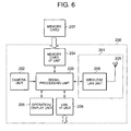
- FIG. 6 schematically shows the structure of a conventional digital camera having a wireless LAN function.
- Reference numeral 200 represents a digital camera having a wireless LAN function.
- a digital camera itself is constituted of a camera unit 202, a signal processing unit 203, a memory card interface unit 204, an operation/display unit 205 and a USB (Universal Serial Bus) interface unit 206.
- USB Universal Serial Bus
- the signal processing unit 203 converts image data input from the camera unit 202 into image data having a predetermined format such as JPEG (Joint Photographic Experts Group) and stores the image data in an external memory card 207 via the memory card interface unit 204.
- JPEG Joint Photographic Experts Group
- the operation/display unit 205 performs image display, various settings and the like.
- the USB interface unit 206 is used for image transfer to PC by using a USB Interface.
- Reference numeral 201 represents a wireless LAN module and is constituted of a wireless LAN unit 208 and an antenna 209.
- the wireless LAN unit 208 receives image data read from the memory card 207 by the signal processing unit 203 and transfers the image data to a display apparatus side via the antenna 209.
- the consumption power can be lowered only by 80 % even if a wireless LAN function is operated by limiting to a short distance and reducing a transmission power.
- transfer from an image input apparatus such as a digital camera to an image display apparatus has a communication type that a transmission ratio occupies most of communications. Accordingly, there is a demand for means of wireless transmission with low consumption power.
- An object of the present invention is to provide an excellent wireless communication system and wireless communication apparatus capable of proper wireless transmission of image data from a portable apparatus such as a digital camera and a mobile phone to an apparatus such as a PC, a television and a printer.
- Another object of the present invention is to provide an excellent wireless communication system and wireless communication apparatus capable of realizing a low consumption power for wireless transmission of image data from a portable apparatus such as a digital camera and a mobile phone to an apparatus such as a PC, a television and a printer.
- Still another object of the present invention is to provide an excellent wireless communication system and wireless communication apparatus capable of realizing a low consumption power in a communication type that a ratio of transmission between apparatus limited to a relatively short distance occupies most of communications.
- the present invention has been made in consideration of the above-described issues and provides a wireless communication system for data transmission by radio waves between a data supply source apparatus and a data provided destination apparatus.
- the wireless communication system is characterized in that: the data supply source apparatus has an RFID (Radio Frequency Identification) tag function that transmits data by a back scattering scheme by absorbing or reflecting external radio waves in accordance with a bit string of the data through an on/off control of an antenna switch to make an antenna in a terminated state or an open state, and the data provided destination apparatus has a reader function that transmits a carrier in a predetermined frequency band and reads data of an RFID tag in accordance with reflected waves; and the data provided destination apparatus transmits a non-modulated carrier or a modulated control signal, and the data supply source apparatus transmits data by absorbing or reflecting external radio waves on a basis of termination control of the antenna and the data provided destination apparatus receives the data on a basis of presence/absence of reflected waves from the supply source apparatus.
- RFID Radio Frequency Identification
- system herein used means a substance of a logical collection of a plurality of apparatus (or functional modules realizing specific functions), irrespective of whether each apparatus and functional module exists in a single housing.
- the data supply source apparatus is a battery-driven type mobile apparatus equipped with a camera function and a function of photographing a moving image or a still image, such as a digital camera and a mobile phone having a camera function.
- the data provided destination apparatus is, for example, a personal computer, a television or other display apparatus, and can display or reproduce and store image data received from a digital camera or a mobile phone having a camera function.
- the wireless communication system of the present invention aims to realize a low consumption power in a communication type that a ratio of transmission between apparatus limited to a relatively short distance occupies most of communications, and wireless communication is conducted by utilizing reflected waves on the basis of a back scattering scheme used by RFID.
- An RFID system itself is widely known to those skilled in the art as an example of a wireless communication means capable of being applied only to a relatively short distance.
- the wireless communication apparatus as a data supply source uses an RFID tag based on a radio wave communication scheme, as a wireless transmission module, in place of a conventional wireless LAN module.
- the wireless transmission module has an antenna, an antenna switch and an antenna load.
- the wireless transmission module unit Upon reception of transmission data made of a bit series, the wireless transmission module unit performs an on/off operation of the antenna switch connected to the antenna in accordance with a bit image of the data. For example, if data is "1", the antenna switch 310 is turned on, whereas if data is "0", it is turned off.
- the antenna switch While the antenna switch is on, the antenna is terminated by the antenna load, whereas while the antenna switch is off, the antenna becomes open. This operation behaves to terminate during on-state and reflect during off-state, with respect to radio waves arriving from a transfer destination. It is therefore possible for the transfer destination to read transmission data by detecting reflection of the transmission radio wave. More specifically, image data is basically transmitted, through a back scattering scheme, as reflected radio waves of radio waves from the transfer destination generated by a change in an antenna load impedance to be caused by the on/off operation of the antenna switch.
- the wireless transmission module unit may be provided further with a band pass filter and ASK detection unit for receiving and processing an external control signal made of ASK modulation waves. These two blocks are used when an ASK-modulated transmittal confirmation signal is received from a transfer destination, and are not necessary for one-way transmission not performing transmittal confirmation of transmission.
- a PSK or FSK modulation scheme may be adopted in addition to an ASK modulation.
- the antenna switch is generally made of a gallium arsenide IC, and its consumption power is several 10 ⁇ W or less. Therefore, the above-described communication scheme can realize ultra low consumption image transmission.
- the band pass filter is used in order to pass frequencies in a predetermined frequency band and attenuate frequencies in other frequency bands.
- the ASK detection unit necessary for transmittal confirmation can realize a consumption power of 30 mW or less.
- the wireless communication system of the present invention As an average power of data transmission by the wireless communication system of the present invention, it is possible to transmit with a power of 10 mW or less for the transmittal confirmation scheme and a power of several 10 ⁇ W for the one-way transmission. This presents an overwhelming performance difference as compared to an average consumption power of a general wireless LAN.
- an excellent wireless communication system and wireless communication apparatus capable of realizing a low consumption power for wireless transmission of image data or the like from a portable apparatus such as a digital camera and a mobile phone to an apparatus such as a PC, a television and a printer.
- the present invention it is possible to provide an excellent wireless communication system and wireless communication apparatus capable of realizing a low consumption power in a communication type that a ratio of transmission between apparatus limited to a relatively short distance occupies most of communications.
- a wireless transmission module of a mobile apparatus as a data transmission side can be realized easily at a lower cost as compared to a wireless LAN. Furthermore, a wireless transmission module on a mobile side is not a subject of a wireless station in the context of the Radio Law, so that an authorization work such as conformity certification is not necessary.
- the present invention aims to realize a low consumption power in a communication type that a ratio of transmission between apparatus limited to a relatively short distance occupies most of communications, and wireless communication is conducted by utilizing reflected waves on the basis of a back scattering scheme used in RFID.
- An RFID system itself is widely known in the art as an example of wireless communication means capable of being applied only in a local area.
- RFID is a system constituted of a tag and a reader in which information stored in the tag is read with the reader in a non-contact manner.
- the RFID system is commonly used worldwide. In some cases, abbreviated RFID is also used.
- Japanese translation is "Recognition System Using High Frequency (Wireless) Waves".
- the RFID tag is a device containing unique identification information and has the operation characteristics that a radio wave having a modulation frequency corresponding to the identification information is oscillated in response to a reception of a radio wave having a specific frequency, and a reader device side can identify what it is in accordance with an oscillation frequency of the RFID tag.
- the communication methods between the tag and a reader/writer includes a magnetic coupling scheme, a magnetic induction scheme, a radio wave communication scheme and the like.
- the present invention is associated with a radio communication scheme using microwaves in a 2.4 GHz band among those schemes (to be described later).
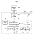
- Fig. 1 schematically shows the hardware structure of a wireless communication apparatus 300 according to an embodiment of the present invention.
- the wireless communication apparatus 300 shown in Fig. 1 corresponds to an apparatus which is a transmission source of image data, such as a digital camera and a mobile phone with a camera, and is driven by a main power source such as a battery (not shown).
- a camera unit 302 a signal processing unit 303, a memory card interface unit 304, an operation/display unit 305 and a USB interface unit 306 are realized by generally the same structures as those of the functional modules represented by reference numerals 202 to 206 of the conventional digital camera with the wireless LAN function module shown in Fig. 6i, and the description thereof is omitted herein.
- the wireless communication apparatus of the embodiment is characterized in that an RFID tag on the basis of a radio wave communication scheme is used as a wireless transmission module 308 in place of the wireless LAN module 201.
- the wireless transmission module 308 is constituted of an antenna 309, an antenna switch 310, an antenna load 311, a band pass filer 312 and an ASK detection unit 313.
- a 2.4 GHz band is used as the frequency of a radio wave.
- the wireless transmission module 308 When an image transfer is performed, upon reception of image data read from the memory card 307 by the signal processing unit 303, the wireless transmission module 308 performs an on/off operation of the antenna switch 310 connected to the antenna 309 in accordance with a bit image of data. For example, if data is "1", the antenna switch 310 is turned on, whereas if data is "0", it is turned off.
- the antenna 309 is terminated by an antenna load 311 of 50 ⁇ , whereas while the antenna switch 310 is off, the antenna 309 becomes open.
- This operation behaves to terminate during on-state and reflect during off-state, relative to a radio wave arriving from a transfer destination (to be described later). It is therefore possible for the transfer destination to read image data by detecting reflection of the transmission radio wave. More specifically, image data is basically transmitted as reflected radio waves of radio waves from the transfer destination generated by a change in an antenna load impedance to be caused by the on/off operation of the antenna switch 310.
- the communication scheme of this type is called a "back scattering scheme".
- a reflected wave signal from the wireless transmission module 308 is equivalent to an ASK modulation wave.
- a PSK or FSK modulation scheme may be adopted in addition to the ASK modulation.
- the antenna switch 310 is generally constituted of an IC of gallium arsenide, and its consumption power is several 10 ⁇ W or less. Therefore, with the above-described communication scheme, wireless image transmission can be realized at ultra low consumption.
- the band pass filter 312 and ASK detection unit 313 are used when an ASK modulated transmittal confirmation signal is received from the transfer destination. These two blocks are not necessary for one-way transmission not performing transmittal confirmation of transmission. On the other hand, if transmittal confirmation is to be performed, this control is executed by the signal processing unit 303.
- the band pass filter 312 is used in order to pass frequencies in the 2.4 GHz band and attenuate frequencies in other frequency bands.
- the ASK detection unit 313 necessary for transmittal confirmation can realize a consumption power of 30 mW or less.
- an average power of data transmission of image data or the like performed by the wireless communication apparatus shown in Fig. 1 is 10 mW or less for the transmittal confirmation scheme and several 10 ⁇ W for the one-way transmission. This presents an overwhelming performance difference as compared to an average consumption power of a general wireless LAN.
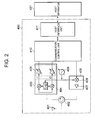
- Fig. 2 schematically shows the hardware structure of a wireless communication apparatus for receiving transmission data from the wireless communication apparatus shown in Fig. 1, according to the embodiment.
- the wireless communication apparatus shown in the figure corresponds to an image reproducing apparatus such as a PC and a television for displaying and outputting received image data, and a printer for printing and outputting.
- the wireless reception module 400 is constituted of an antenna 401 in the 2.4 GHz band, a circulator 402, a reception unit 403, a transmission unit 406, a frequency synthesizer 409, a communication control unit 410 and a host interface unit 411.
- the reception unit 403 is constituted of an orthogonal detection unit 404 and an AGC amplifier unit 405, and the transmission unit 406 is constituted of a mixer 408 and a power amplifier 407.
- the host interface unit 411 is connected to a host apparatus 412 such as a PC, and transfers received image data.
- Transmission of a non-modulated carrier from the wireless reception module 400 is realized by applying a certain d.c. voltage to the mixer 408 from the communication control unit 410.
- a frequency of the non-modulated carrier to be transmitted is determined by a frequency of the frequency synthesizer under control of the communication control unit 410.
- the 2.4 GHz band is used.
- the non-modulated carrier output from the mixer 408 is amplified by the power amplifier 407 to a predetermined level and transmitted from the antenna 401 via the circulator 402.
- a frequency of reflected waves from the image transmission apparatus 300 is the same as the transmission frequency from the wireless reception module 400 (described above).
- the reflected waves are received at the antenna 401, and input to the reception unit 403 via the circulator 402. Since a local frequency same as that of transmission is input to the orthogonal detection unit 404, an ASK modulation wave multiplied by the image transmission apparatus 300 appears as an output of the orthogonal detection unit 404. However, since the received signal has a different local phase from that of the received signal, a modulation signal corresponding to the phase difference appears as an I-axis signal and a Q-axis signal.
- the AGC amplifier unit 405 has a gain controlled to an optimum value, and its output signal is passed to the communication control unit 410.
- the communication control unit 410 demodulates the I-axis and Q-axis signals into digital data, and the correct data is transferred to the host apparatus 412 via the host interface unit 411.
- the communication control unit 410 transfers, to the mixer 408 to make ASK modulation, digital data of an positive response ACK (Acknowledgement) if the received packet data is correct or digital data of a negative response NAK (Negative Acknowledgement) if it is incorrect. Whether data is correct or incorrect is judged from a CRC (Cyclic Redundancy Check) code added to an image data packet.
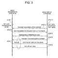
- Fig. 3 shows a control sequence for wireless transmission between the wireless communication apparatus 300 shown in Fig. 1 as an image transmission apparatus and the wireless communication apparatus 400 shown in Fig. 2 as an image display apparatus. In the example shown in Fig. 3, however, it is assumed both the apparatus make transmittal confirmation. This control sequence will be described below.
- a data transmission mode is set manually.
- a data reception wait mode is set manually.
- the image display apparatus transmits a non-modulated carrier.
- the image transmission apparatus Upon reception of the non-modulated carrier, the image transmission apparatus issues a data transmission request by using reflected waves.
- the image display apparatus Upon reception of the data transmission request, the image display apparatus transmits transmission permission through ASK modulation.
- the image display apparatus transmits a non-modulated carrier.
- the image transmission apparatus Upon reception of the non-modulated carrier, the image transmission apparatus transmits packet zed data by using reflected waves.
- the image display apparatus sends the positive response ACK (Acknowledgement) through ASK modulation if the received packet data is correct. If incorrect, the negative response NAK (Negative Acknowledgement) is transmitted. Whether data is correct or incorrect can be judged from the CRC (Cyclic Redundancy Check) code added to a data packet.
- CRC Cyclic Redundancy Check
- a command for the image transmission apparatus may be contained in the same transmittal confirmation signal.
- the image display apparatus issues a request of a slide show to the image transmission apparatus. It is therefore possible for the image display apparatus to control remotely the image transmission apparatus.
- the wireless transmission module 308 is built in a photographing apparatus such as a digital camera on the image transmission apparatus side, obviously the gist of the present invention is not limited thereto.
- the wireless transmission module may be an external adaptor or the like in the form of external connection to the apparatus main body, in conformity with USB and other interface standards.
- Fig. 4 schematically shows an example of the structure that a wireless transmission module of an adapter type is used.
- an image transmission apparatus has a camera unit 602, a signal processing unit 603, a memory card interface unit 604, an operation/display unit 605, a USB interface unit 606 and a memory card 607.
- These components may be generally the same as the components of the conventional digital camera having the wireless LAN function shown in Fig. 6 and represented by reference numerals 202 to 207.
- the USB interface unit 606 operates as a slave and is used when the signal processing unit 603 transfers objective image data read from the memory card 607 via the memory card interface unit 604, via a USB cable to PC as a USB host.
- the USB Interface operates being switched to a host and is connected to a wireless transmission module 601 of an external slave side apparatus connected to a USB, so that an apparatus equivalent to that shown in Fig. 1 can be configured.
- the wireless transmission module 601 can be considered as an adapter having an outer appearance such as represented by reference numeral 620 having a USB connector and an antenna 609.
- the wireless transmission module 601 shown in Fig. 4 is generally the same as the wireless transmission module 308 shown in Fig. 1 excepting that a USB interface unit 614 is added.
- the wireless transmission module has an antenna 609, an antenna switch 610, an antenna load 611, a band pass filter 612 and an ASK detection unit 613.
- a communication control unit 608 receives image data read from the memory card 607 by the signal processing unit 603, via the host side USB interface unit 606 and the slave side USB interface unit 614.
- an on/off control is performed for the antenna switch 610 connected to the antenna 609.
- the antenna switch 610 is turned on if data is "1" and it is turned off if data is "0".
- the antenna 609 is terminated by the antenna load 611 of 50 ⁇ , while during off-state, the antenna 609 becomes open. With this operation, the wireless transmission module 601 behaves to terminate during on-state and reflect during off-state, with respect to radio waves arriving from the transfer destination.
- the band pass filter 612 and the ASK detection unit 613 are used when an ASK modulated transmittal confirmation signal is received from the transfer destination. These two blocks are not necessary for one-way transmission not performing transmittal confirmation of transmission. Control of transmittal confirmation is executed by the communication control unit 608.
- the band pass filter 612 is used in order to pass frequencies in the 2.4 GHz band and attenuate frequencies in other frequency bands.
- USB is used as a connection interface to an apparatus main body such as a digital camera, it is obvious that other interfaces may also be used.
- a reflected wave transmission system generally adopts a modulation scheme having a relatively low bit rate, such as ASK (Amplitude Shift Keying).
- ASK Amplitude Shift Keying
- BPSK modulation can be realized easily by controlling a load impedance of a directional antenna on a reflector side to dispose "0" and "1" signals in a signal space, for example, by an on/off operation of antenna termination.
- these modulation schemes are associated with a problem in terms of a transmission rate.
- a phase modulation scheme having a higher bit rate such as BPSK, QPSK and eight-phase PSK modulations.
- a low consumption power can be realized for wireless transmission of image data or the like from a portable apparatus such as a digital camera and a mobile phone to an apparatus such as a PC, a television and a printer.
- a low consumption power can be realized in a communication type that a ratio of transmission between apparatus limited to a relatively short distance occupies most of communications.
- a wireless transmission module of a mobile apparatus as a data transmission side can be realized easily at a low cost as compared to a wireless LAN. Furthermore, a wireless transmission module on a mobile side is not a subject of a wireless station in the context of the Radio Law, so that an authorization work such as conformity certification is not necessary.
Landscapes
- Engineering & Computer Science (AREA)
- Physics & Mathematics (AREA)
- General Physics & Mathematics (AREA)
- Theoretical Computer Science (AREA)
- Computer Hardware Design (AREA)
- Microelectronics & Electronic Packaging (AREA)
- Computer Networks & Wireless Communication (AREA)
- Artificial Intelligence (AREA)
- Computer Vision & Pattern Recognition (AREA)
- Signal Processing (AREA)
- Studio Devices (AREA)
- Mobile Radio Communication Systems (AREA)
- Transceivers (AREA)
- Near-Field Transmission Systems (AREA)
- Transmitters (AREA)
Applications Claiming Priority (2)
| Application Number | Priority Date | Filing Date | Title |
|---|---|---|---|
| JP2003291809 | 2003-08-11 | ||
| PCT/JP2004/011161 WO2005015764A1 (fr) | 2003-08-11 | 2004-08-04 | Systeme et dispositif de communications radio |
Publications (3)
| Publication Number | Publication Date |
|---|---|
| EP1646155A1 true EP1646155A1 (fr) | 2006-04-12 |
| EP1646155A4 EP1646155A4 (fr) | 2007-10-31 |
| EP1646155B1 EP1646155B1 (fr) | 2010-03-03 |
Family
ID=34131678
Family Applications (1)
| Application Number | Title | Priority Date | Filing Date |
|---|---|---|---|
| EP04748236A Expired - Lifetime EP1646155B1 (fr) | 2003-08-11 | 2004-08-04 | Systeme et dispositif de communications radio |
Country Status (7)
| Country | Link |
|---|---|
| US (1) | US7986234B2 (fr) |
| EP (1) | EP1646155B1 (fr) |
| JP (1) | JPWO2005015764A1 (fr) |
| KR (1) | KR101105476B1 (fr) |
| CN (1) | CN100401644C (fr) |
| DE (1) | DE602004025811D1 (fr) |
| WO (1) | WO2005015764A1 (fr) |
Cited By (7)
| Publication number | Priority date | Publication date | Assignee | Title |
|---|---|---|---|---|
| US7511669B2 (en) | 2004-06-25 | 2009-03-31 | Sony Corporation | Antenna Device and Radio Communication Apparatus |
| US7697892B2 (en) | 2004-06-25 | 2010-04-13 | Sony Corporation | Wireless communication system, cradle apparatus, and portable device |
| US7769867B2 (en) | 2004-08-18 | 2010-08-03 | Sony Corporation | Mountable memory card and method for communicating, controlling, accessing and/or using the same |
| US7949258B2 (en) | 2004-06-28 | 2011-05-24 | Sony Corporation | Radio communication system, radio communication apparatus and radio communication method as well as computer program |
| WO2013170338A1 (fr) * | 2012-05-14 | 2013-11-21 | Tag-Comm Inc. | Appareil de génération de canaux de données dédiés dans un système rfid à rétrodiffusion utilisant un modulateur delta-sigma passe-bande |
| WO2013170337A1 (fr) * | 2012-05-14 | 2013-11-21 | Tag-Comm Inc. | Appareil de génération de canaux de données dédiés dans un système rfid à rétrodiffusion utilisant un modulateur delta-sigma passe-bas |
| US10079704B2 (en) | 2014-09-22 | 2018-09-18 | Drnc Holdings, Inc. | Transmission apparatus for a wireless device using delta-sigma modulation |
Families Citing this family (22)
| Publication number | Priority date | Publication date | Assignee | Title |
|---|---|---|---|---|
| JP2006013843A (ja) * | 2004-06-25 | 2006-01-12 | Sony Corp | 無線通信システム、無線通信装置及び無線通信方法、並びにコンピュータ・プログラム |
| US7372831B2 (en) * | 2004-08-11 | 2008-05-13 | Lg Electronics Inc. | Packet transmission acknowledgement in wireless communication system |
| EP1776811B1 (fr) * | 2004-08-11 | 2013-03-13 | LG Electronics Inc. | Accuse de reception d`emission de paquets dans un systeme de communication sans fil |
| WO2006096782A1 (fr) * | 2005-03-07 | 2006-09-14 | Sensormatic Electronics Corporation | Transmission adaptative d'un signal pour l'activation d'une etiquette |
| KR100694378B1 (ko) * | 2005-09-22 | 2007-03-12 | 주식회사 팬택 | Rfid 리더를 포함한 이동 통신 단말기 및 그 송수신방법 |
| KR100833454B1 (ko) * | 2006-11-06 | 2008-05-29 | 엘에스산전 주식회사 | Rfid 시스템 |
| KR100825362B1 (ko) * | 2007-02-22 | 2008-04-28 | 국민대학교산학협력단 | Rfid 리더와 rfid 태그 간의 통신 방법 |
| JP4582106B2 (ja) * | 2007-03-27 | 2010-11-17 | ブラザー工業株式会社 | 通信装置 |
| JP5033598B2 (ja) | 2007-11-28 | 2012-09-26 | 株式会社日立製作所 | 表示装置および映像機器 |
| JP5068780B2 (ja) * | 2009-03-04 | 2012-11-07 | 東京エレクトロン株式会社 | 成膜装置、成膜方法、プログラム、およびコンピュータ可読記憶媒体 |
| JP2011248768A (ja) * | 2010-05-28 | 2011-12-08 | Sony Corp | 情報処理装置、情報処理システム及びプログラム |
| KR20120059938A (ko) | 2010-12-01 | 2012-06-11 | 한국전자통신연구원 | 무선 주파수 식별 태그 |
| US20130038895A1 (en) * | 2011-08-08 | 2013-02-14 | Alexander Govyadinov | Mobile communication device and printer having a particulate sensor for air quality monitoring |
| US9014625B2 (en) * | 2012-05-29 | 2015-04-21 | Tag-Comm Inc. | Method and apparatus for generating dedicated data channels in inductive coupled RFID systems using band-pass modulation |
| US9014624B2 (en) * | 2012-05-29 | 2015-04-21 | Tag-Comm Inc. | Method and apparatus for generating dedicated data channels in inductive coupled RFID systems |
| JP6190617B2 (ja) * | 2013-04-22 | 2017-08-30 | 尼寺空圧工業株式会社 | エアーコンプレッサ |
| WO2015111833A1 (fr) | 2014-01-21 | 2015-07-30 | 에스케이플래닛 주식회사 | Appareil et procédé pour fournir des annonces publicitaires virtuelles |
| CN106485291A (zh) * | 2015-08-24 | 2017-03-08 | 瑞章科技有限公司 | 射频识别系统、标签和读写器,及纠错方法 |
| CN113055328B (zh) * | 2021-02-08 | 2022-09-09 | 西安电子科技大学 | 一种基于低功耗反向散射放大标签的bpsk调制电路及其方法 |
| JP7619617B2 (ja) * | 2021-02-22 | 2025-01-22 | 国立大学法人東北大学 | 通信回路,通信システム及び通信方法 |
| CN115621706A (zh) * | 2021-07-12 | 2023-01-17 | 中兴通讯股份有限公司 | 天线装置和基站 |
| CN116208849B (zh) * | 2023-05-05 | 2023-07-18 | 中国科学技术大学 | 一种超低功耗物联网图像采集和传输系统及方法 |
Family Cites Families (50)
| Publication number | Priority date | Publication date | Assignee | Title |
|---|---|---|---|---|
| JPH03171384A (ja) | 1989-11-30 | 1991-07-24 | Sony Corp | 情報読取装置 |
| JPH05304320A (ja) * | 1991-03-27 | 1993-11-16 | Semiconductor Energy Lab Co Ltd | 超伝導薄膜トランジスタ及びその作製方法 |
| US5776278A (en) * | 1992-06-17 | 1998-07-07 | Micron Communications, Inc. | Method of manufacturing an enclosed transceiver |
| EP0646983B1 (fr) | 1993-10-04 | 1998-09-02 | Amtech Corporation | Antenne microbande à rayonnement rétrodiffusé modulé |
| FR2724746A1 (fr) | 1994-09-16 | 1996-03-22 | Int Network For Mobile Electro | Dispositif et procede de tele-controle d'un objet |
| JP2866016B2 (ja) * | 1994-12-22 | 1999-03-08 | 三菱電機株式会社 | Icカードのリード・ライト装置の変調器、その復調器 |
| CN1107922C (zh) * | 1995-06-16 | 2003-05-07 | 罗姆股份有限公司 | 半导体器件,使用同样器件的ic卡和通信系统 |
| US5940006A (en) * | 1995-12-12 | 1999-08-17 | Lucent Technologies Inc. | Enhanced uplink modulated backscatter system |
| JP3435288B2 (ja) * | 1996-06-20 | 2003-08-11 | ペンタックス株式会社 | カメラシステム |
| US6408095B1 (en) * | 1996-08-27 | 2002-06-18 | Canon Kabushiki Kaisha | System, apparatus and method for communication, display and output of images |
| US6545709B2 (en) * | 1996-09-02 | 2003-04-08 | Canon Kabushiki Kaisha | Wireless receiving apparatus and method therefor |
| JPH11120305A (ja) | 1997-10-14 | 1999-04-30 | Mitsubishi Electric Corp | 非接触icカードシステム |
| JPH11146435A (ja) * | 1997-11-11 | 1999-05-28 | Matsushita Electric Ind Co Ltd | 無線選択呼出受信機及び外部登録装置 |
| JPH11326507A (ja) * | 1998-01-19 | 1999-11-26 | Zebra Technol Corp | フォワ―ド・エラ―訂正システムを有する電子識別システム |
| US6122329A (en) * | 1998-02-06 | 2000-09-19 | Intermec Ip Corp. | Radio frequency identification interrogator signal processing system for reading moving transponders |
| US6275476B1 (en) * | 1998-02-19 | 2001-08-14 | Micron Technology, Inc. | Method of addressing messages and communications system |
| JPH11355277A (ja) * | 1998-06-11 | 1999-12-24 | Canon Inc | 無線データ通信システムおよび無線データ通信方法 |
| DE19832628C2 (de) | 1998-07-21 | 2000-10-12 | Daimler Chrysler Ag | Transponderanordnung |
| US6192222B1 (en) * | 1998-09-03 | 2001-02-20 | Micron Technology, Inc. | Backscatter communication systems, interrogators, methods of communicating in a backscatter system, and backscatter communication methods |
| FI116957B (fi) | 1998-10-29 | 2006-04-13 | Nokia Corp | Menetelmä langattoman laitteen ja elektroniikkalaitteen välistä tiedonsiirtoa varten ja tiedonsiirtolaite |
| GB2345811B (en) | 1999-01-16 | 2001-04-04 | Marconi Caswell Ltd | Radio frequency receiver circuit |
| US6720866B1 (en) * | 1999-03-30 | 2004-04-13 | Microchip Technology Incorporated | Radio frequency identification tag device with sensor input |
| GB2351193A (en) * | 1999-06-17 | 2000-12-20 | Marconi Electronic Syst Ltd | AM receiver |
| JP4350237B2 (ja) * | 1999-11-08 | 2009-10-21 | 富士フイルム株式会社 | カメラ |
| US6400903B1 (en) * | 1999-12-23 | 2002-06-04 | Paul Conoval | Remote camera relay controller method and apparatus |
| JP2001339327A (ja) * | 2000-05-29 | 2001-12-07 | Sony Corp | 情報授受装置および情報授受方法および情報担持装置および情報担持方法 |
| JP3513084B2 (ja) * | 2000-06-14 | 2004-03-31 | 株式会社東芝 | 情報処理システム、情報機器及び情報処理方法 |
| FR2817370B1 (fr) * | 2000-11-27 | 2004-04-09 | Jouan Sa | Installation de traitement de produits, poste de travail et support pour recipients de produits correspondants |
| JP2002199324A (ja) * | 2000-12-26 | 2002-07-12 | Canon Inc | 再生装置、電子カメラ装置、電子カメラ装置の機能拡張装置、電子カメラ装置の制御方法、及び制御プログラムを提供する媒体 |
| US7664296B2 (en) * | 2001-01-31 | 2010-02-16 | Fujifilm Corporation | Image recording method and system, image transmitting method, and image recording apparatus |
| JP4168634B2 (ja) * | 2001-02-16 | 2008-10-22 | 株式会社ニコン | 撮影システム及び撮影情報伝送システム |
| JP2002318999A (ja) | 2001-04-23 | 2002-10-31 | Patoraito:Kk | 携帯型情報処理装置およびそれを用いた情報提供方法 |
| JP2002320115A (ja) * | 2001-04-24 | 2002-10-31 | Olympus Optical Co Ltd | デジタルカメラ、及びデジタル撮像システム |
| JP2002329180A (ja) * | 2001-04-27 | 2002-11-15 | Toshiba Corp | 無線通信機能を有するメモリカード及びそのデータ通信方法 |
| JP4660013B2 (ja) | 2001-05-23 | 2011-03-30 | 富士フイルム株式会社 | カメラシステム、カメラ装置、画像記録媒体、プリントシステム、及びサーバ装置 |
| JP4422930B2 (ja) * | 2001-08-07 | 2010-03-03 | パイオニア株式会社 | 情報処理システム、情報処理システムの情報処理方法、情報処理装置および情報処理プログラム |
| JP2003069935A (ja) | 2001-08-23 | 2003-03-07 | Fuji Photo Film Co Ltd | 画像データの分類保存方法 |
| JP4069453B2 (ja) * | 2001-08-28 | 2008-04-02 | ソニー株式会社 | 情報処理装置および方法 |
| SE522027C2 (sv) * | 2001-11-13 | 2004-01-07 | Tagmaster Ab | Kommunikationsenhet |
| US7215976B2 (en) * | 2001-11-30 | 2007-05-08 | Symbol Technologies, Inc. | RFID device, system and method of operation including a hybrid backscatter-based RFID tag protocol compatible with RFID, bluetooth and/or IEEE 802.11x infrastructure |
| US7382405B2 (en) * | 2001-12-03 | 2008-06-03 | Nikon Corporation | Electronic apparatus having a user identification function and user identification method |
| US20030103144A1 (en) * | 2001-12-04 | 2003-06-05 | Robert Sesek | Digital camera having image transfer method and system |
| JP3806038B2 (ja) * | 2002-01-07 | 2006-08-09 | 富士写真フイルム株式会社 | 画像処理システム及び撮像装置 |
| JP4060854B2 (ja) * | 2002-08-01 | 2008-03-12 | 株式会社日立製作所 | 移動体識別装置の質問器 |
| JP2004120263A (ja) | 2002-09-25 | 2004-04-15 | Fuji Photo Film Co Ltd | 携帯用電子機器 |
| JP2004215090A (ja) * | 2003-01-07 | 2004-07-29 | Canon Inc | 画像通信システム及び画像処理装置 |
| US7019639B2 (en) * | 2003-02-03 | 2006-03-28 | Ingrid, Inc. | RFID based security network |
| US20040183918A1 (en) * | 2003-03-20 | 2004-09-23 | Eastman Kodak Company | Producing enhanced photographic products from images captured at known picture sites |
| JP4738771B2 (ja) * | 2004-07-29 | 2011-08-03 | ルネサスエレクトロニクス株式会社 | 通信システム、及び通信方法 |
| US8872633B2 (en) * | 2005-07-20 | 2014-10-28 | Intelleflex Corporation | Ramped interrogation power levels |
-
2004
- 2004-08-04 WO PCT/JP2004/011161 patent/WO2005015764A1/fr not_active Ceased
- 2004-08-04 US US10/567,622 patent/US7986234B2/en not_active Expired - Fee Related
- 2004-08-04 KR KR1020067001625A patent/KR101105476B1/ko not_active Expired - Fee Related
- 2004-08-04 EP EP04748236A patent/EP1646155B1/fr not_active Expired - Lifetime
- 2004-08-04 DE DE602004025811T patent/DE602004025811D1/de not_active Expired - Lifetime
- 2004-08-04 CN CNB2004800229195A patent/CN100401644C/zh not_active Expired - Fee Related
- 2004-08-04 JP JP2005512937A patent/JPWO2005015764A1/ja active Pending
Cited By (11)
| Publication number | Priority date | Publication date | Assignee | Title |
|---|---|---|---|---|
| US7511669B2 (en) | 2004-06-25 | 2009-03-31 | Sony Corporation | Antenna Device and Radio Communication Apparatus |
| US7697892B2 (en) | 2004-06-25 | 2010-04-13 | Sony Corporation | Wireless communication system, cradle apparatus, and portable device |
| US7949258B2 (en) | 2004-06-28 | 2011-05-24 | Sony Corporation | Radio communication system, radio communication apparatus and radio communication method as well as computer program |
| US7769867B2 (en) | 2004-08-18 | 2010-08-03 | Sony Corporation | Mountable memory card and method for communicating, controlling, accessing and/or using the same |
| WO2013170338A1 (fr) * | 2012-05-14 | 2013-11-21 | Tag-Comm Inc. | Appareil de génération de canaux de données dédiés dans un système rfid à rétrodiffusion utilisant un modulateur delta-sigma passe-bande |
| WO2013170337A1 (fr) * | 2012-05-14 | 2013-11-21 | Tag-Comm Inc. | Appareil de génération de canaux de données dédiés dans un système rfid à rétrodiffusion utilisant un modulateur delta-sigma passe-bas |
| US8590790B1 (en) | 2012-05-14 | 2013-11-26 | Tag-Comm Inc. | Method and apparatus for generating dedicated data channels in backscatter RFID systems |
| US8847834B2 (en) | 2012-05-14 | 2014-09-30 | Tag-Comm Inc. | Method and apparatus for generating dedicated data channels in backscatter RFID systems using band-pass modulation |
| JP2015526918A (ja) * | 2012-05-14 | 2015-09-10 | タグ−コム インコーポレイテッド | 低域通過デルタシグマ変調器を用いて後方散乱rfidシステム内に専用データチャネルを生成する装置 |
| US10079704B2 (en) | 2014-09-22 | 2018-09-18 | Drnc Holdings, Inc. | Transmission apparatus for a wireless device using delta-sigma modulation |
| US10419254B2 (en) | 2014-09-22 | 2019-09-17 | Drnc Holdings, Inc. | Transmission apparatus for a wireless device using delta-sigma modulation |
Also Published As
| Publication number | Publication date |
|---|---|
| US20070024444A1 (en) | 2007-02-01 |
| KR20060039927A (ko) | 2006-05-09 |
| EP1646155A4 (fr) | 2007-10-31 |
| JPWO2005015764A1 (ja) | 2007-10-04 |
| KR101105476B1 (ko) | 2012-01-13 |
| US7986234B2 (en) | 2011-07-26 |
| DE602004025811D1 (de) | 2010-04-15 |
| EP1646155B1 (fr) | 2010-03-03 |
| CN1836379A (zh) | 2006-09-20 |
| CN100401644C (zh) | 2008-07-09 |
| WO2005015764A1 (fr) | 2005-02-17 |
Similar Documents
| Publication | Publication Date | Title |
|---|---|---|
| US7986234B2 (en) | Wireless communication system and wireless communication apparatus | |
| KR101126438B1 (ko) | 어댑터 장치 및 메모리 장치 | |
| JP4218463B2 (ja) | 無線通信装置並びに無線通信システム | |
| US7181241B2 (en) | Memory card, memory card communication control method, electronic device, and wireless communication system | |
| EP1760899B1 (fr) | Système de communication sans fil, unité en berceau et dispositif mobile | |
| EP1630969B1 (fr) | Système, appareil et procédé de radiocommunication | |
| JP4333449B2 (ja) | 無線伝送システム及び無線伝送装置 | |
| US7949258B2 (en) | Radio communication system, radio communication apparatus and radio communication method as well as computer program | |
| JP4385858B2 (ja) | 無線通信システム及び無線通信装置 | |
| JP4872267B2 (ja) | アダプタ装置及びメモリ装置、並びにコネクタ装置 | |
| JP2005333169A (ja) | 無線通信システム及び無線通信装置 | |
| JP2005136666A (ja) | 無線通信装置 | |
| JP2007052559A (ja) | 無線データ伝送システム、情報処理装置及び情報処理方法、並びにコンピュータ・プログラム | |
| HK1103262A (en) | Wireless communication system, wireless communication unit, wireless communication method, and computer program |
Legal Events
| Date | Code | Title | Description |
|---|---|---|---|
| PUAI | Public reference made under article 153(3) epc to a published international application that has entered the european phase |
Free format text: ORIGINAL CODE: 0009012 |
|
| 17P | Request for examination filed |
Effective date: 20060203 |
|
| AK | Designated contracting states |
Kind code of ref document: A1 Designated state(s): DE FR GB |
|
| DAX | Request for extension of the european patent (deleted) | ||
| RBV | Designated contracting states (corrected) |
Designated state(s): DE FR GB |
|
| RIC1 | Information provided on ipc code assigned before grant |
Ipc: H04B 5/02 20060101ALI20070918BHEP Ipc: G06K 17/00 20060101ALI20070918BHEP Ipc: G06K 19/07 20060101AFI20070918BHEP Ipc: G06K 7/00 20060101ALI20070918BHEP Ipc: H04B 1/59 20060101ALI20070918BHEP |
|
| A4 | Supplementary search report drawn up and despatched |
Effective date: 20071002 |
|
| 17Q | First examination report despatched |
Effective date: 20080109 |
|
| GRAP | Despatch of communication of intention to grant a patent |
Free format text: ORIGINAL CODE: EPIDOSNIGR1 |
|
| GRAS | Grant fee paid |
Free format text: ORIGINAL CODE: EPIDOSNIGR3 |
|
| GRAA | (expected) grant |
Free format text: ORIGINAL CODE: 0009210 |
|
| AK | Designated contracting states |
Kind code of ref document: B1 Designated state(s): DE FR GB |
|
| REG | Reference to a national code |
Ref country code: GB Ref legal event code: FG4D |
|
| REF | Corresponds to: |
Ref document number: 602004025811 Country of ref document: DE Date of ref document: 20100415 Kind code of ref document: P |
|
| PLBE | No opposition filed within time limit |
Free format text: ORIGINAL CODE: 0009261 |
|
| STAA | Information on the status of an ep patent application or granted ep patent |
Free format text: STATUS: NO OPPOSITION FILED WITHIN TIME LIMIT |
|
| 26N | No opposition filed |
Effective date: 20101206 |
|
| REG | Reference to a national code |
Ref country code: GB Ref legal event code: 746 Effective date: 20120703 |
|
| REG | Reference to a national code |
Ref country code: DE Ref legal event code: R084 Ref document number: 602004025811 Country of ref document: DE Effective date: 20120614 |
|
| PGFP | Annual fee paid to national office [announced via postgrant information from national office to epo] |
Ref country code: GB Payment date: 20140820 Year of fee payment: 11 Ref country code: FR Payment date: 20140821 Year of fee payment: 11 |
|
| GBPC | Gb: european patent ceased through non-payment of renewal fee |
Effective date: 20150804 |
|
| REG | Reference to a national code |
Ref country code: FR Ref legal event code: ST Effective date: 20160429 |
|
| PG25 | Lapsed in a contracting state [announced via postgrant information from national office to epo] |
Ref country code: GB Free format text: LAPSE BECAUSE OF NON-PAYMENT OF DUE FEES Effective date: 20150804 |
|
| PG25 | Lapsed in a contracting state [announced via postgrant information from national office to epo] |
Ref country code: FR Free format text: LAPSE BECAUSE OF NON-PAYMENT OF DUE FEES Effective date: 20150831 |
|
| PGFP | Annual fee paid to national office [announced via postgrant information from national office to epo] |
Ref country code: DE Payment date: 20170822 Year of fee payment: 14 |
|
| REG | Reference to a national code |
Ref country code: DE Ref legal event code: R119 Ref document number: 602004025811 Country of ref document: DE |
|
| PG25 | Lapsed in a contracting state [announced via postgrant information from national office to epo] |
Ref country code: DE Free format text: LAPSE BECAUSE OF NON-PAYMENT OF DUE FEES Effective date: 20190301 |