EP1646540B1 - Systeme d'essuie-glace, notamment pour un vehicule automobile - Google Patents
Systeme d'essuie-glace, notamment pour un vehicule automobile Download PDFInfo
- Publication number
- EP1646540B1 EP1646540B1 EP04738486A EP04738486A EP1646540B1 EP 1646540 B1 EP1646540 B1 EP 1646540B1 EP 04738486 A EP04738486 A EP 04738486A EP 04738486 A EP04738486 A EP 04738486A EP 1646540 B1 EP1646540 B1 EP 1646540B1
- Authority
- EP
- European Patent Office
- Prior art keywords
- wiper device
- spring element
- bolt
- coupling part
- plate
- Prior art date
- Legal status (The legal status is an assumption and is not a legal conclusion. Google has not performed a legal analysis and makes no representation as to the accuracy of the status listed.)
- Expired - Lifetime
Links
- 230000008878 coupling Effects 0.000 claims description 24
- 238000010168 coupling process Methods 0.000 claims description 24
- 238000005859 coupling reaction Methods 0.000 claims description 24
- 238000001746 injection moulding Methods 0.000 claims description 3
- 230000005540 biological transmission Effects 0.000 description 3
- 230000033001 locomotion Effects 0.000 description 2
- 230000006835 compression Effects 0.000 description 1
- 238000007906 compression Methods 0.000 description 1
- 230000001419 dependent effect Effects 0.000 description 1
- 238000004519 manufacturing process Methods 0.000 description 1
- 239000002184 metal Substances 0.000 description 1
- 239000000243 solution Substances 0.000 description 1
Images

Classifications
-
- B—PERFORMING OPERATIONS; TRANSPORTING
- B60—VEHICLES IN GENERAL
- B60S—SERVICING, CLEANING, REPAIRING, SUPPORTING, LIFTING, OR MANOEUVRING OF VEHICLES, NOT OTHERWISE PROVIDED FOR
- B60S1/00—Cleaning of vehicles
- B60S1/02—Cleaning windscreens, windows or optical devices
- B60S1/56—Cleaning windscreens, windows or optical devices specially adapted for cleaning other parts or devices than front windows or windscreens
- B60S1/58—Cleaning windscreens, windows or optical devices specially adapted for cleaning other parts or devices than front windows or windscreens for rear windows
-
- B—PERFORMING OPERATIONS; TRANSPORTING
- B60—VEHICLES IN GENERAL
- B60S—SERVICING, CLEANING, REPAIRING, SUPPORTING, LIFTING, OR MANOEUVRING OF VEHICLES, NOT OTHERWISE PROVIDED FOR
- B60S1/00—Cleaning of vehicles
- B60S1/02—Cleaning windscreens, windows or optical devices
- B60S1/04—Wipers or the like, e.g. scrapers
- B60S1/32—Wipers or the like, e.g. scrapers characterised by constructional features of wiper blade arms or blades
- B60S1/34—Wiper arms; Mountings therefor
- B60S1/342—Wiper arms; Mountings therefor with means for temporarily uncoupling the wiper arm from the drive
-
- B—PERFORMING OPERATIONS; TRANSPORTING
- B60—VEHICLES IN GENERAL
- B60S—SERVICING, CLEANING, REPAIRING, SUPPORTING, LIFTING, OR MANOEUVRING OF VEHICLES, NOT OTHERWISE PROVIDED FOR
- B60S1/00—Cleaning of vehicles
- B60S1/02—Cleaning windscreens, windows or optical devices
- B60S1/04—Wipers or the like, e.g. scrapers
- B60S1/06—Wipers or the like, e.g. scrapers characterised by the drive
- B60S1/16—Means for transmitting drive
- B60S1/18—Means for transmitting drive mechanically
-
- B—PERFORMING OPERATIONS; TRANSPORTING
- B60—VEHICLES IN GENERAL
- B60S—SERVICING, CLEANING, REPAIRING, SUPPORTING, LIFTING, OR MANOEUVRING OF VEHICLES, NOT OTHERWISE PROVIDED FOR
- B60S1/00—Cleaning of vehicles
- B60S1/02—Cleaning windscreens, windows or optical devices
- B60S1/04—Wipers or the like, e.g. scrapers
- B60S1/32—Wipers or the like, e.g. scrapers characterised by constructional features of wiper blade arms or blades
-
- B—PERFORMING OPERATIONS; TRANSPORTING
- B60—VEHICLES IN GENERAL
- B60S—SERVICING, CLEANING, REPAIRING, SUPPORTING, LIFTING, OR MANOEUVRING OF VEHICLES, NOT OTHERWISE PROVIDED FOR
- B60S1/00—Cleaning of vehicles
- B60S1/02—Cleaning windscreens, windows or optical devices
- B60S1/56—Cleaning windscreens, windows or optical devices specially adapted for cleaning other parts or devices than front windows or windscreens
- B60S1/58—Cleaning windscreens, windows or optical devices specially adapted for cleaning other parts or devices than front windows or windscreens for rear windows
- B60S1/583—Cleaning windscreens, windows or optical devices specially adapted for cleaning other parts or devices than front windows or windscreens for rear windows including wiping devices
Definitions
- the invention relates to a windshield wiper device, in particular for a motor vehicle, according to the preamble of the independent claim.
- windscreen wiper devices for motor vehicles which are suitable for wiping a movable disk, for example a rear window of a mini van.
- These essentially comprise a first coupling part, which is rotatably drivable by a drive part, a second coupling part, which is non-rotatably connected to a wiper shaft, to which a wiper lever is attached with a wiper blade.
- a resilient element for torque transmission is provided at the first or second coupling part.
- Such a windshield wiper device is known from DE-A-100 34 042 known.
- the resilient element is in this case designed as a helical spring, which is operatively connected to a bolt.
- Coil spring and bolts are mounted in a sleeve, which requires a relatively large amount of space. In addition, this is complex and costly, which is particularly noticeable in mass production negative.
- the windshield wiper device according to the invention with the features of the main claim has the advantage that is saved by a substantially flat spring element space and a simple and inexpensive solution is available.
- the means has a coupling element, so that a secure transmission of torque is ensured.
- the spring element is designed as a leaf or spiral spring.
- the first coupling part comprises a plate with at least one opening, which is able to cooperate with the coupling element. In this way a good and safe torque transmission is ensured without the need for additional components.
- the plate has a guide in the region of opening, which in particular directs the bolt into the opening.
- the plate is made of plastic, in particular in an injection molding process.
- the bolt advantageously engages in a coupled state in the opening.
- the bolt is pressed in the disengaged state by the tensioned spring element on the plate, so that a reliable engagement is ensured.
- the second coupling part comprises a crank and a bearing housing, and the spring element between bearing housing and crank is held.
- the spring element between bearing housing and crank is held.
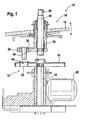
- a windshield wiper device 10 according to the invention is shown in a cross-sectional view.
- This essentially comprises a first coupling part 12, and a second coupling part 14.
- the first coupling part 12 consists essentially of a plate 16, which is made of plastic in an injection molding process. In an alternative embodiment, this may also consist of metal.
- the plate 16 is rotatably connected to an output shaft 18 which is driven by a drive device 20.
- the plate 16 also has an opening 22 which is arranged in the radially outer region. In motor vehicles, the first clutch part 12 and the drive device 20 is attached to the tailgate.
- the second clutch part 14 is attached to the motor vehicle to a rear window 15 and essentially comprises a crank 24 which is rotatably connected to a wiper shaft 26. At the end of the wiper shaft 26 facing away from the crank 24, this has a cone 28 which serves for fastening a wiper lever, which is not shown here for the sake of clarity.
- the wiper shaft 26 is mounted in bearings 32 in a bearing housing 30.
- the wiper shaft 26 is arranged on the same axis as the output shaft 18.
- a means 34 for transmitting torque is arranged.
- This essentially comprises a cylindrical bolt as a coupling element 36, which is connected by a spring element 38 resiliently movable with the crank 24.
- the spring element 38 is disposed on the side facing away from the plate 16 of the crank 24, between the bearing housing 30 and crank 24. It is designed as a leaf spring, but alternatively the training as a spiral spring is possible.
- the bolt 36 passes through the crank 24 and is supported by this. Alternatively, of course, a further storage may be provided.
- At its end facing away from the plate 16 of the bolt with the leaf spring 38 is operatively connected. He is here arranged the way that it engages in the engaged state in the opening 22 of the first coupling part 12, so that a torque from the first coupling part 12 can be transmitted to the second coupling part 14.
- the function of the two coupling parts 12, 14 will be explained briefly. If the rear window 15 of the motor vehicle is closed, then the opening 22 is not necessarily in alignment with the bolt 36. The bolt 36 thus sits on the plate 16, wherein it recedes under tension of the spring element 38. Puts the drive means 20, the plate 16 in a rotational movement, ie, the windshield wiper device 10 is put into operation, the bolt 36 slides on the plate 16 and is pressed by the spring element 38 on this. If the opening 22 is now aligned with the bolt 36, then the bolt 36 slides into the opening 22, the spring element 38 being relaxed. To improve the guidance of the bolt 36 on the plate 16 guides 40 are provided in the region of the opening 22, which consist essentially of rectangular in cross-section walls. The first and second coupling parts 12, 14 are thus engaged, whereby the wiper shaft 26 is driven and thus set in motion.
- the spring element 38 is formed as a leaf spring, which is of substantially planar shape and helically winds around the bolt 36.
- the spring element 38 is fork-shaped and engages in a groove 42 of the bolt 36, so that the bolt 36 is operatively connected to the spring element 38.
- the width of the groove 42 is suitably slightly larger than the thickness of the leaf or coil spring, so that an angular offset during compression is compensated.
- the other end of the spring element 38 is clamped between crank 24 and bearing housing 30.
- the spring element 38 is shown in a plan view. It essentially comprises an eye 44, which serves for fastening between the crank 24 and the bearing housing 30. Alternatively, the leaf spring 38 may be fixed instead of only by an eye 44 on one side of the bearing housing 30. At the same time, the spring element 38 with the eye 44 serves as Anlauf- and / or spring washer of the bearing 32. This is followed by a screw-like portion 46, which is fork-shaped at its inner end 48.
- a fork-like portion may also be provided or the spring element 38 may be fastened on the crank 24 in a different manner.
- a separate fastening means such as a rivet or a screw can be provided.
- the spring element 38 may be provided with the bolt 36, so the means 34, also on the first coupling part 12 and the opening 22 on the second coupling part 14.
Landscapes
- Engineering & Computer Science (AREA)
- Mechanical Engineering (AREA)
- Connection Of Motors, Electrical Generators, Mechanical Devices, And The Like (AREA)
- Springs (AREA)
- Transmission Devices (AREA)
Claims (8)
- Système d'essuie-glace (10), en particulier pour véhicule automobile, pour essuyer une vitre mobile (15), avec une première pièce de couplage (12), qui peut être entraînée en rotation au moyen d'un dispositif d'entraînement (20), et une deuxième pièce de couplage (14), qui est solidaire en rotation d'un arbre d'essuie-glace (26) sur lequel un levier de balai peut être fixé, dans lequel il est prévu sur la première ou la deuxième pièce de couplage (12, 14) un moyen (34) pour la transmission du couple de rotation, dans lequel le moyen (34) comprend un élément de ressort essentiellement plan (38) et un boulon (36), caractérisé en ce que l'élément de ressort (38) s'enroule en hélice autour du boulon (36).
- Système d'essuie-glace (10) selon la revendication 1, caractérisé en ce que l'élément de ressort (38) se présente sous la forme d'un ressort à lame ou d'un ressort spiral.
- Système d'essuie-glace (10) selon l'une quelconque des revendications précédentes, caractérisé en ce que la première pièce de couplage (12) comprend une plaque (16) avec au moins une ouverture (22).
- Système d'essuie-glace (10) selon la revendication 3, caractérisé en ce que la plaque présente un guidage (40) dans la région de l'ouverture (22).
- Système d'essuie-glace (10) selon la revendication 3 et/ou la revendication 4, caractérisé en ce que la plaque (16) est fabriquée en matière plastique, en particulier par un procédé de coulée par injection.
- Système d'essuie-glace (10) selon l'une quelconque des revendications 3 à 5, caractérisé en ce que le boulon (36) s'engage dans l'ouverture (22) à l'état couplé.
- Système d'essuie-glace (10) selon l'une quelconque des revendications 3 à 6, caractérisé en ce que le boulon (36) est poussé sur la plaque (16) par l'élément de ressort (38) sous contrainte à l'état découplé.
- Système d'essuie-glace (10) selon l'une quelconque des revendications 3 à 7, caractérisé en ce que la deuxième pièce de couplage (14) comprend une manivelle (24) portant le moyen (34) et un boîtier de palier (30) et l'élément de ressort (38) est tenu entre la manivelle (24) et le boîtier de palier (30).
Applications Claiming Priority (2)
| Application Number | Priority Date | Filing Date | Title |
|---|---|---|---|
| DE10331568A DE10331568A1 (de) | 2003-07-11 | 2003-07-11 | Scheibenwischvorrichtung, insbesondere für ein Kraftfahrzeug |
| PCT/DE2004/000958 WO2005009812A1 (fr) | 2003-07-11 | 2004-05-07 | Systeme d'essuie-glace, notamment pour un vehicule automobile |
Publications (2)
| Publication Number | Publication Date |
|---|---|
| EP1646540A1 EP1646540A1 (fr) | 2006-04-19 |
| EP1646540B1 true EP1646540B1 (fr) | 2009-10-14 |
Family
ID=33546997
Family Applications (1)
| Application Number | Title | Priority Date | Filing Date |
|---|---|---|---|
| EP04738486A Expired - Lifetime EP1646540B1 (fr) | 2003-07-11 | 2004-05-07 | Systeme d'essuie-glace, notamment pour un vehicule automobile |
Country Status (6)
| Country | Link |
|---|---|
| EP (1) | EP1646540B1 (fr) |
| JP (1) | JP4171043B2 (fr) |
| KR (1) | KR101074280B1 (fr) |
| DE (2) | DE10331568A1 (fr) |
| ES (1) | ES2331611T3 (fr) |
| WO (1) | WO2005009812A1 (fr) |
Families Citing this family (5)
| Publication number | Priority date | Publication date | Assignee | Title |
|---|---|---|---|---|
| DE102005048342A1 (de) * | 2005-01-18 | 2006-07-27 | Robert Bosch Gmbh | Montagehilfe |
| EP1997699B1 (fr) * | 2007-05-30 | 2011-10-26 | Robert Bosch GmbH | Dispositif d'essuie-glace dans un véhicule automobile |
| JP5090075B2 (ja) * | 2007-06-15 | 2012-12-05 | アスモ株式会社 | 車両用ワイパ装置 |
| DE102009046979A1 (de) * | 2009-11-23 | 2011-05-26 | Robert Bosch Gmbh | Scheibenwischervorrichtung für ein Fahrzeug |
| JP5822576B2 (ja) * | 2011-07-13 | 2015-11-24 | プレス工業株式会社 | 建設機械のワイパー駆動装置 |
Family Cites Families (4)
| Publication number | Priority date | Publication date | Assignee | Title |
|---|---|---|---|---|
| GB355521A (en) * | 1930-09-03 | 1931-08-27 | Vauxhall Motors Ltd | Improvements relating to windscreen wipers for motor vehicles |
| DE19735182C1 (de) | 1997-08-14 | 1998-09-24 | Webasto Karosseriesysteme | Wippvorrichtung für ein öffnungsfähiges Fahrzeugdach und Verfahren zur Montage einer solchen Vorrichtung |
| JP2000255390A (ja) | 1999-03-03 | 2000-09-19 | Asmo Co Ltd | 車両用ワイパ装置 |
| DE10034042A1 (de) * | 2000-07-13 | 2002-02-21 | Bosch Gmbh Robert | Wischanlage |
-
2003
- 2003-07-11 DE DE10331568A patent/DE10331568A1/de not_active Ceased
-
2004
- 2004-05-07 JP JP2006500493A patent/JP4171043B2/ja not_active Expired - Fee Related
- 2004-05-07 ES ES04738486T patent/ES2331611T3/es not_active Expired - Lifetime
- 2004-05-07 EP EP04738486A patent/EP1646540B1/fr not_active Expired - Lifetime
- 2004-05-07 KR KR1020067000628A patent/KR101074280B1/ko not_active Expired - Fee Related
- 2004-05-07 WO PCT/DE2004/000958 patent/WO2005009812A1/fr not_active Ceased
- 2004-05-07 DE DE502004010238T patent/DE502004010238D1/de not_active Expired - Lifetime
Also Published As
| Publication number | Publication date |
|---|---|
| KR20060030901A (ko) | 2006-04-11 |
| DE10331568A1 (de) | 2005-01-27 |
| ES2331611T3 (es) | 2010-01-11 |
| JP4171043B2 (ja) | 2008-10-22 |
| DE502004010238D1 (de) | 2009-11-26 |
| WO2005009812A1 (fr) | 2005-02-03 |
| JP2006521949A (ja) | 2006-09-28 |
| EP1646540A1 (fr) | 2006-04-19 |
| KR101074280B1 (ko) | 2011-10-18 |
Similar Documents
| Publication | Publication Date | Title |
|---|---|---|
| EP2094541B1 (fr) | Dispositif d'entraînement électromagnétique destiné à être utilisé dans le hayon arrière d'un véhicule automobile | |
| EP1713669B1 (fr) | Dispositif d'essuie-glace, en particulier pour vehicule a moteur | |
| EP1713668A1 (fr) | Dispositif d'essuie-glace notamment destine a un vehicule | |
| DE102004008333A1 (de) | Scheibenwischvorrichtung | |
| EP0843767B1 (fr) | Unite d'entrainement a moteur et transmission pour un composant pouvant se deplacer entre deux positions extremes | |
| DE102010063058B4 (de) | Verbindungsvorrichtung für einen Heckklappenantrieb eines Fahrzeugs | |
| DE102006027345B4 (de) | Wischanlage für Fahrzeugscheiben | |
| EP1646540B1 (fr) | Systeme d'essuie-glace, notamment pour un vehicule automobile | |
| EP1636075B1 (fr) | Systeme d'essuie-glace, destine en particulier a un vehicule automobile | |
| DE102010000726A1 (de) | Wischerantrieb für eine Scheibenwischanlage eines Fahrzeugs | |
| EP1735193B1 (fr) | Systeme d'essuie-glace, notamment pour vehicule automobile | |
| EP1682389B1 (fr) | Dispositif essuie-glace, notamment pour un vehicule automobile | |
| EP1587721B1 (fr) | Dispositif essuie-glace, en particulier pour un vehicule automobile | |
| EP1480859B1 (fr) | Dispositif d'essuie-glace, en particulier pour vehicule a moteur | |
| DE102007037712B4 (de) | Verstellvorrichtung, Fahrzeugsitz und Montageverfahren | |
| EP1054797A1 (fr) | Bras de monture d'essuie-glace a quatre points articules pour systeme d'essuie-glace | |
| EP1663739B1 (fr) | Dispositif d'essuyage de vitre destine en particulier a un vehicule automobile | |
| EP1763460B1 (fr) | Dispositf de fixation d'un essuie-glace sur un vehicle automobile | |
| DE3045560C2 (de) | Antriebsvorrichtung für Scheibenwischer an Kraftfahrzeugen | |
| EP0908361B1 (fr) | Agencement d'essuyage pour une véhicule | |
| DE102009055173A1 (de) | Scheibenwischvorrichtung, insbesondere für ein Kraftfahrzeug | |
| EP1910139A1 (fr) | Dispositif d'essuie-glace, en particulier pour vehicule automobile | |
| DE102008054746A1 (de) | Scheibenwischvorrichtung, insbesondere für eine Heckscheibe eines Kraftfahrzeugs | |
| DE102018218080A1 (de) | Verstellvorrichtung zum Betätigen einer drehbar gelagerten Klappe im Kraftfahrzeug, sowie Verfahren zum Herstellen einer solchen Verstellvorrichtung | |
| DE19618608C1 (de) | Klemmrichtgesperre, insb. für Fensterheber und Sitzverstellungen an Kraftfahrzeugen |
Legal Events
| Date | Code | Title | Description |
|---|---|---|---|
| PUAI | Public reference made under article 153(3) epc to a published international application that has entered the european phase |
Free format text: ORIGINAL CODE: 0009012 |
|
| 17P | Request for examination filed |
Effective date: 20060213 |
|
| AK | Designated contracting states |
Kind code of ref document: A1 Designated state(s): CZ DE ES FR GB IT |
|
| DAX | Request for extension of the european patent (deleted) | ||
| RBV | Designated contracting states (corrected) |
Designated state(s): CZ DE ES FR GB IT |
|
| 17Q | First examination report despatched |
Effective date: 20081126 |
|
| GRAP | Despatch of communication of intention to grant a patent |
Free format text: ORIGINAL CODE: EPIDOSNIGR1 |
|
| GRAS | Grant fee paid |
Free format text: ORIGINAL CODE: EPIDOSNIGR3 |
|
| GRAA | (expected) grant |
Free format text: ORIGINAL CODE: 0009210 |
|
| AK | Designated contracting states |
Kind code of ref document: B1 Designated state(s): CZ DE ES FR GB IT |
|
| REG | Reference to a national code |
Ref country code: GB Ref legal event code: FG4D Free format text: NOT ENGLISH |
|
| REF | Corresponds to: |
Ref document number: 502004010238 Country of ref document: DE Date of ref document: 20091126 Kind code of ref document: P |
|
| REG | Reference to a national code |
Ref country code: ES Ref legal event code: FG2A Ref document number: 2331611 Country of ref document: ES Kind code of ref document: T3 |
|
| PLBE | No opposition filed within time limit |
Free format text: ORIGINAL CODE: 0009261 |
|
| STAA | Information on the status of an ep patent application or granted ep patent |
Free format text: STATUS: NO OPPOSITION FILED WITHIN TIME LIMIT |
|
| 26N | No opposition filed |
Effective date: 20100715 |
|
| REG | Reference to a national code |
Ref country code: FR Ref legal event code: PLFP Year of fee payment: 12 |
|
| PGFP | Annual fee paid to national office [announced via postgrant information from national office to epo] |
Ref country code: ES Payment date: 20150520 Year of fee payment: 12 Ref country code: CZ Payment date: 20150427 Year of fee payment: 12 Ref country code: GB Payment date: 20150521 Year of fee payment: 12 |
|
| PGFP | Annual fee paid to national office [announced via postgrant information from national office to epo] |
Ref country code: FR Payment date: 20150519 Year of fee payment: 12 Ref country code: IT Payment date: 20150519 Year of fee payment: 12 |
|
| PGFP | Annual fee paid to national office [announced via postgrant information from national office to epo] |
Ref country code: DE Payment date: 20150723 Year of fee payment: 12 |
|
| REG | Reference to a national code |
Ref country code: DE Ref legal event code: R119 Ref document number: 502004010238 Country of ref document: DE |
|
| GBPC | Gb: european patent ceased through non-payment of renewal fee |
Effective date: 20160507 |
|
| PG25 | Lapsed in a contracting state [announced via postgrant information from national office to epo] |
Ref country code: CZ Free format text: LAPSE BECAUSE OF NON-PAYMENT OF DUE FEES Effective date: 20160507 |
|
| PG25 | Lapsed in a contracting state [announced via postgrant information from national office to epo] |
Ref country code: IT Free format text: LAPSE BECAUSE OF NON-PAYMENT OF DUE FEES Effective date: 20160507 |
|
| REG | Reference to a national code |
Ref country code: FR Ref legal event code: ST Effective date: 20170131 |
|
| PG25 | Lapsed in a contracting state [announced via postgrant information from national office to epo] |
Ref country code: FR Free format text: LAPSE BECAUSE OF NON-PAYMENT OF DUE FEES Effective date: 20160531 Ref country code: DE Free format text: LAPSE BECAUSE OF NON-PAYMENT OF DUE FEES Effective date: 20161201 |
|
| PG25 | Lapsed in a contracting state [announced via postgrant information from national office to epo] |
Ref country code: GB Free format text: LAPSE BECAUSE OF NON-PAYMENT OF DUE FEES Effective date: 20160507 |
|
| PG25 | Lapsed in a contracting state [announced via postgrant information from national office to epo] |
Ref country code: ES Free format text: LAPSE BECAUSE OF NON-PAYMENT OF DUE FEES Effective date: 20160508 |
|
| REG | Reference to a national code |
Ref country code: ES Ref legal event code: FD2A Effective date: 20180626 |