EP1647341A2 - Méthode de fabrication des ailettes ondulées et bloc d'échangeur de chaleur comprenant des ailettes ondulées produit en applicant cette méthode - Google Patents
Méthode de fabrication des ailettes ondulées et bloc d'échangeur de chaleur comprenant des ailettes ondulées produit en applicant cette méthode Download PDFInfo
- Publication number
- EP1647341A2 EP1647341A2 EP05021790A EP05021790A EP1647341A2 EP 1647341 A2 EP1647341 A2 EP 1647341A2 EP 05021790 A EP05021790 A EP 05021790A EP 05021790 A EP05021790 A EP 05021790A EP 1647341 A2 EP1647341 A2 EP 1647341A2
- Authority
- EP
- European Patent Office
- Prior art keywords
- tubes
- heat exchanger
- gills
- rows
- thermal barrier
- Prior art date
- Legal status (The legal status is an assumption and is not a legal conclusion. Google has not performed a legal analysis and makes no representation as to the accuracy of the status listed.)
- Granted
Links
Images

Classifications
-
- B—PERFORMING OPERATIONS; TRANSPORTING
- B21—MECHANICAL METAL-WORKING WITHOUT ESSENTIALLY REMOVING MATERIAL; PUNCHING METAL
- B21D—WORKING OR PROCESSING OF SHEET METAL OR METAL TUBES, RODS OR PROFILES WITHOUT ESSENTIALLY REMOVING MATERIAL; PUNCHING METAL
- B21D53/00—Making other particular articles
- B21D53/02—Making other particular articles heat exchangers or parts thereof, e.g. radiators, condensers fins, headers
- B21D53/08—Making other particular articles heat exchangers or parts thereof, e.g. radiators, condensers fins, headers of both metal tubes and sheet metal
-
- F—MECHANICAL ENGINEERING; LIGHTING; HEATING; WEAPONS; BLASTING
- F28—HEAT EXCHANGE IN GENERAL
- F28D—HEAT-EXCHANGE APPARATUS, NOT PROVIDED FOR IN ANOTHER SUBCLASS, IN WHICH THE HEAT-EXCHANGE MEDIA DO NOT COME INTO DIRECT CONTACT
- F28D1/00—Heat-exchange apparatus having stationary conduit assemblies for one heat-exchange medium only, the media being in contact with different sides of the conduit wall, in which the other heat-exchange medium is a large body of fluid, e.g. domestic or motor car radiators
- F28D1/02—Heat-exchange apparatus having stationary conduit assemblies for one heat-exchange medium only, the media being in contact with different sides of the conduit wall, in which the other heat-exchange medium is a large body of fluid, e.g. domestic or motor car radiators with heat-exchange conduits immersed in the body of fluid
- F28D1/04—Heat-exchange apparatus having stationary conduit assemblies for one heat-exchange medium only, the media being in contact with different sides of the conduit wall, in which the other heat-exchange medium is a large body of fluid, e.g. domestic or motor car radiators with heat-exchange conduits immersed in the body of fluid with tubular conduits
- F28D1/0408—Multi-circuit heat exchangers, e.g. integrating different heat exchange sections in the same unit or heat exchangers for more than two fluids
-
- F—MECHANICAL ENGINEERING; LIGHTING; HEATING; WEAPONS; BLASTING
- F28—HEAT EXCHANGE IN GENERAL
- F28F—DETAILS OF HEAT-EXCHANGE AND HEAT-TRANSFER APPARATUS, OF GENERAL APPLICATION
- F28F1/00—Tubular elements; Assemblies of tubular elements
- F28F1/10—Tubular elements and assemblies thereof with means for increasing heat-transfer area, e.g. with fins, with projections, with recesses
- F28F1/12—Tubular elements and assemblies thereof with means for increasing heat-transfer area, e.g. with fins, with projections, with recesses the means being only outside the tubular element
- F28F1/126—Tubular elements and assemblies thereof with means for increasing heat-transfer area, e.g. with fins, with projections, with recesses the means being only outside the tubular element consisting of zig-zag shaped fins
- F28F1/128—Fins with openings, e.g. louvered fins
Definitions
- the invention relates to a method for producing a corrugated fin for a heat exchanger block comprising at least two heat exchangers.
- the invention further relates to a heat exchanger block, comprising at least two heat exchangers, according to the preamble of claim 9.
- Heat exchanger blocks or heat exchanger modules which consist of at least two different réelle undergraduatetragem were known under the name protected for the applicant Monoblock .
- a coolant flowed through by coolant on the primary side and a condenser through which refrigerant flows on the primary side are integrated into a heat exchanger block, wherein both heat exchangers are arranged one behind the other in the air flow direction and have common corrugated fins, so-called continuous ribs, overflowed by ambient air.
- the entire heat exchanger block preferably made of aluminum, is soldered "in one shot” in a soldering oven.
- such a heat exchanger block may also include other heat exchangers, such as a charge air cooler.
- such a monoblock which is also characterized in that at least one heat exchanger, preferably the cooler, has no conventional tube sheet, but instead flared end flat tubes with each other with their long sides and their Narrow sides are soldered to a collection box.
- This design brings significant benefits in the depth, ie in the air flow direction.
- the heat exchangers carry their heat to the ambient air via a common or continuous rib, which has the mechanical advantage that it gives the heat exchanger block the required stiffness, but thermodynamically has the disadvantage that a heat conduction through the rib of a Heat exchanger to the other takes place, for example, from the radiator to the condenser. This is not wanted.
- EP-A 1 241 424 a thermal barrier for a corrugated fin of a so-called duplex heat exchanger is proposed, which consists of so-called half gills, d. H. a gill carved out of the rib plane and shaped upwards or downwards.
- this solution is waste-free, but has the disadvantage that rib material is required for the bridging zone or thermal barrier zone, which does not serve for heat transfer.
- the corrugated fin is first produced from a flat metal strip into which gills for improving the heat transfer are cut by means of cutting rollers, which are arranged in rows transversely to the rolling direction.
- the rib is then separated in the region of the thermal barrier, ie approximately in the middle, in each case between directly or indirectly adjacent gills and then pulled apart (transversely to the rolling direction).
- the rib is pleated, ie wavy.
- the separation of the rib is made without waste, so that no rib material particles are incurred, which must be disposed of. This facilitates the manufacturing process.
- the rib can pull apart like a concertina or garland, resulting in a thermally effective "exclusion zone", ie a thermal barrier and only one or two thin material webs are retained, which hold the rib parts together and allow only a small heat conduction ,
- This separation technique also larger distances can be bridged, which depends on the design of the relevant plantetragerblvckes, ie the distance of the rows of tubes.
- the solution according to the invention is the more advantageous the material saving in the rib, the greater the distance to be bridged.
- corrugated fin according to the invention need not necessarily - as explained above - be carried out in a continuous process with an endless metal belt, which is guided by a rotating pair of rollers. Rather, it is also within the scope of the invention, a rib with gills and cuts from a metal sheet (board)montstanzen and then pull apart to form the thermal barrier.
- the separation of the rib is carried out by running in the rolling direction and / or transverse to the rolling direction cuts, d. H. small cuts between adjacent gills, in the same gill row and between adjacent gill rows.
- This cutting technique has the advantage that it can be achieved directly during rolling by slight changes in the cutting rollers.
- the cuts according to the invention are thus produced, as it were, in one operation with the cutting of the gills.
- the distances of the gills in a row in the area of the exclusion zone are increased - this results in other cutting combinations and another geometric design of the connecting webs.
- both rib parts form a coherent structure, which can be further processed as a part and mounted (cassetted) in the heat exchanger block.
- a heat exchanger block consisting of at least two heat exchangers, is equipped with a corrugated fin produced according to the invention. Since this heat exchanger at least two rows of flat tubes and the corrugated fin according to the invention, despite thermal barrier is a continuous rib, it can be much easier cassettes with the tubes of the heat exchanger, ie prepare for the soldering process.
- the thermal barrier or the bridging is formed only by thin connecting webs of the fin material, said webs are arranged at an acute or obtuse angle to each other and made without waste.
- the thermal barrier or thermal insulation is achieved by a relatively low thermal conductivity cross section and a relatively large length due to the angular arrangement of the legs.
- Fig. 1 shows three production sections a), b) and c) for a corrugated fin 1, which is shown in c) in the installed state of a heat exchanger block 2 only partially shown.
- the heat exchanger block 2 consists - as is known - of two heat transfer, which are shown schematically here by a first row of tubes 3 of a coolant radiator and a second row of tubes 4 of a refrigerant condenser.
- the series 3 consists of flat tubes 5, which are flowed through by coolant of a coolant circuit of an internal combustion engine of a motor vehicle, not shown, and the row 4 of multi-chamber flat tubes 6, which are traversed by refrigerant of a refrigerant circuit, not shown, of an air conditioning system of a motor vehicle.
- the two rows of tubes 3, 4 have a distance A, which is given on the one hand for reasons of isolation and on the other hand due to the design of the heat exchanger block.
- the corrugated fins 1 are between the Flat tubes 4 and 5 are arranged, wherein each corrugated fin 1 consists of two rib sections 1 a for the flat tubes 5 of the radiator and 1b for the flat tubes 4 of the capacitor. These rib sections 1a, 1b are occupied with gills 7, which serve to improve the heat transfer with the ambient air, which flows in the direction of the arrow L via the corrugated fins 1.
- the gills 7 may be the same or different for the rib sections 1a, 1b, depending on the design of the relevant heat exchanger.
- a connecting web 8 is arranged, which has two acute angles to each other arranged legs 8a, 8b, which are connected with their free ends with the rib portions 1a, 1b.
- the connecting web 8 acts as a so-called thermal barrier and prevents or reduces the heat conduction from one rib section 1 a to the other 1 b.
- thermal barrier is not to be understood as meaning that heat conduction between the fin sections 1a, 1b is completely excluded, but interpreted in accordance with the prior art explained in the introduction in that the heat conduction from one to the other rib section is so
- the two legs 8a, 8b of the connecting web 8 have in total a length which is greater than the distance A between the two rib sections 1a, 1b or the rows of tubes 3 This means that a longer path than the direct path of the distance A results for the heat conduction between the two rib sections 1a, 1b: This results in a further reduction of the heat conduction.
- the process section a) shows a flat, endless metal strip 9 of width B1 with uniformly arranged rows 10 of gills 11.
- the gills 11 are in a conventional manner when passing through cutting rollers, not shown in the direction of the arrow W, ie in the rolling direction in the metal strip 9 cut.
- separating cuts 12a, 12b, 12c, 12d which extend in the rolling direction W and run transversely to the rolling direction are arranged.
- the fourth separating cut 12d is arranged transversely to the rolling direction W and connects the two longitudinal cuts 12b, 12c.
- This cutting pattern 12a to 12d is repeated continuously in the rolling direction W.
- the closed gills 11 are separated, and the metal strip 9 'can - as shown in the method section b) - pull apart transverse to the rolling direction W. This separation takes place after the metal strip 9 has passed through the cutting rollers, not shown.
- an enlarged width B2 of the metal strip 9 'and on the other hand a separation zone of the width T is achieved.
- the metal strip 9 ' is now divided into two sections of width R1 and width R2, which are interconnected by the aforementioned connecting webs 8.
- the geometric formation of the connecting webs 8 with the legs 8a, 8b takes place by plastic deformation of the metal strip 9 ', wherein each two adjacent pairs of legs 8a, 8b of the metal strip 9' form a rhombus 13.
- a thermal barrier or restricted zone of the width T has been created, without material waste.
- the process sections a) and b) are thus carried out completely without cutting.
- the metal strip 9 is pleated in the stretched to the width B2 state, d. H. to the finished corrugated fin 1, shown in section c), formed.
- the corrugated fin 1 can then - as described above - cassetted with the flat tubes 5, 6 and added to a complete heat exchanger block 2, which is then "finished in a shot” soldered in a soldering oven, not shown.
- the pleating takes place simultaneously with the cutting of the gills.
- the spreading of the rib is then advantageously then with the help of guide rollers.
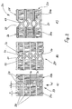
- Fig. 2 shows in three process sections a), b) and c) the production of a corrugated fin 20, which is shown in the finished and installed state in the picture c).
- the corrugated fin 20 consists - as in the first embodiment - of two sections 20a, 20b, which has a thermal barrier 21 in the form of two Connecting webs 22, 23 are interconnected.
- the continuous corrugated fin 20 is part of aticianschreiberblokkes 24 shown only partially, which consists of two réelletragem, which are represented by a first row of tubes 25 and a second row of tubes 26 - analogous to the previous embodiment.
- the connecting webs 22, 23 are each composed of two legs, which together form an obtuse angle.
- Each corrugated fin 20 thus has two connecting webs 22, 23, whose legs form approximately the shape of an X.
- a flat metal strip 27 is shown, which is occupied in a similar manner as in the previous embodiment with gills 28.
- the metal strip 27 has a left portion 27a and a right portion 27b, in which the distance of the gills transverse to the rolling direction W has the value a, while the distance of the gills 28 in the central region, d. H. between sections 27a, 27b is increased to a dimension b. In this central region of the width b, separating cuts 29 between adjacent gills 28 are introduced transversely to the rolling direction W into the metal strip 27.
- transverse separating cuts 29 in the rolling direction W extending separating cuts 30 are mounted.
- the transverse and longitudinal cuts 29, 30 are made during the cutting of the gills by means not shown, known per se cutting rollers. Analogously to the embodiment according to FIG. 1, the separating cuts 29, 30 are also produced in one operation with the cutting of the gills 28.
- the process step b) shows the metal strip 27 'in a state after pulling apart transversely to the rolling direction W.
- the process step b) shows the metal strip 27 'in a state after pulling apart transversely to the rolling direction W.
Landscapes
- Engineering & Computer Science (AREA)
- Physics & Mathematics (AREA)
- Mechanical Engineering (AREA)
- Thermal Sciences (AREA)
- General Engineering & Computer Science (AREA)
- Geometry (AREA)
- Heat-Exchange Devices With Radiators And Conduit Assemblies (AREA)
Applications Claiming Priority (1)
| Application Number | Priority Date | Filing Date | Title |
|---|---|---|---|
| DE200410050160 DE102004050160A1 (de) | 2004-10-14 | 2004-10-14 | Verfahren zum Herstellen einer Wellrippe und Wärmeübertragerblock mit nach dem Verfahren hergestellten Wellrippen |
Publications (3)
| Publication Number | Publication Date |
|---|---|
| EP1647341A2 true EP1647341A2 (fr) | 2006-04-19 |
| EP1647341A3 EP1647341A3 (fr) | 2006-05-31 |
| EP1647341B1 EP1647341B1 (fr) | 2008-03-12 |
Family
ID=35502009
Family Applications (1)
| Application Number | Title | Priority Date | Filing Date |
|---|---|---|---|
| EP20050021790 Expired - Lifetime EP1647341B1 (fr) | 2004-10-14 | 2005-10-06 | Méthode de fabrication des ailettes ondulées et bloc d'échangeur de chaleur comprenant des ailettes ondulées produit en applicant cette méthode |
Country Status (2)
| Country | Link |
|---|---|
| EP (1) | EP1647341B1 (fr) |
| DE (2) | DE102004050160A1 (fr) |
Cited By (1)
| Publication number | Priority date | Publication date | Assignee | Title |
|---|---|---|---|---|
| WO2014126634A1 (fr) * | 2013-02-13 | 2014-08-21 | Carrier Corporation | Échangeur de chaleur à tubes plats et à faisceaux multiples |
Families Citing this family (2)
| Publication number | Priority date | Publication date | Assignee | Title |
|---|---|---|---|---|
| EP4238669A1 (fr) | 2022-03-02 | 2023-09-06 | Recutech S.r.o. | Procédé de fabrication d'une plaque d'échange chaleur-humidité d'un échangeur enthalpique air-air, plaque d'échange chaleur-humidité et échangeur enthalpique |
| CN116020931B (zh) * | 2023-03-29 | 2023-06-27 | 适新科技(苏州)有限公司 | 金属薄片的筋槽成型设备及工艺 |
Citations (7)
| Publication number | Priority date | Publication date | Assignee | Title |
|---|---|---|---|---|
| EP0367078A1 (fr) | 1988-10-24 | 1990-05-09 | Sanden Corporation | Echangeur de chaleur |
| EP0431917A1 (fr) | 1989-12-07 | 1991-06-12 | Showa Aluminum Kabushiki Kaisha | Duplex échangeur de chaleur |
| DE19722097A1 (de) | 1997-05-27 | 1998-12-03 | Behr Gmbh & Co | Wärmeübertrager sowie Wärmeübertrageranordnung für ein Kraftfahrzeug |
| DE19808202A1 (de) | 1998-02-27 | 1999-09-02 | Behr Gmbh & Co | Wärmeübertrageranordnung für ein Kraftfahrzeug |
| EP1164345A1 (fr) | 1999-12-14 | 2001-12-19 | Denso Corporation | Echangeur de chaleur |
| EP1176378A1 (fr) | 2000-07-25 | 2002-01-30 | Valeo Thermique Moteur | Procédé de fabrication d'une ailette d'échangeur de chaleur, ailettes selon le procédé et module d'échange comportant ces ailettes |
| EP1241424A2 (fr) | 2001-03-16 | 2002-09-18 | Calsonic Kansei Corporation | Structure de bloc d'échangeur de chaleur combiné |
-
2004
- 2004-10-14 DE DE200410050160 patent/DE102004050160A1/de not_active Withdrawn
-
2005
- 2005-10-06 DE DE200550003178 patent/DE502005003178D1/de not_active Expired - Lifetime
- 2005-10-06 EP EP20050021790 patent/EP1647341B1/fr not_active Expired - Lifetime
Patent Citations (7)
| Publication number | Priority date | Publication date | Assignee | Title |
|---|---|---|---|---|
| EP0367078A1 (fr) | 1988-10-24 | 1990-05-09 | Sanden Corporation | Echangeur de chaleur |
| EP0431917A1 (fr) | 1989-12-07 | 1991-06-12 | Showa Aluminum Kabushiki Kaisha | Duplex échangeur de chaleur |
| DE19722097A1 (de) | 1997-05-27 | 1998-12-03 | Behr Gmbh & Co | Wärmeübertrager sowie Wärmeübertrageranordnung für ein Kraftfahrzeug |
| DE19808202A1 (de) | 1998-02-27 | 1999-09-02 | Behr Gmbh & Co | Wärmeübertrageranordnung für ein Kraftfahrzeug |
| EP1164345A1 (fr) | 1999-12-14 | 2001-12-19 | Denso Corporation | Echangeur de chaleur |
| EP1176378A1 (fr) | 2000-07-25 | 2002-01-30 | Valeo Thermique Moteur | Procédé de fabrication d'une ailette d'échangeur de chaleur, ailettes selon le procédé et module d'échange comportant ces ailettes |
| EP1241424A2 (fr) | 2001-03-16 | 2002-09-18 | Calsonic Kansei Corporation | Structure de bloc d'échangeur de chaleur combiné |
Cited By (2)
| Publication number | Priority date | Publication date | Assignee | Title |
|---|---|---|---|---|
| WO2014126634A1 (fr) * | 2013-02-13 | 2014-08-21 | Carrier Corporation | Échangeur de chaleur à tubes plats et à faisceaux multiples |
| CN104995471A (zh) * | 2013-02-13 | 2015-10-21 | 开利公司 | 多束扁平化管热交换器 |
Also Published As
| Publication number | Publication date |
|---|---|
| DE102004050160A1 (de) | 2006-04-27 |
| EP1647341A3 (fr) | 2006-05-31 |
| EP1647341B1 (fr) | 2008-03-12 |
| DE502005003178D1 (de) | 2008-04-24 |
Similar Documents
| Publication | Publication Date | Title |
|---|---|---|
| EP0519334B1 (fr) | Echangeur de chaleur à tubes plats, procédé pour sa fabrication, applications et tubes plats pour échangeur de chaleur | |
| EP2117742B1 (fr) | Procédé de production de tuyaux plats et laminoir pour la mise en oeuvre du procédé. | |
| DE69330803T2 (de) | Kühlröhren für Wärmetauscher | |
| DE69309061T2 (de) | Wärmtetauscherrohre | |
| DE3781651T2 (de) | Verfahren zum herstellen einer waermetauschereinheit mit integrierten kuehlrippen. | |
| DE69004793T2 (de) | Fahrzeugkondensator. | |
| DE60028660T2 (de) | Rohr sowie Verfahren und Vorrichtung zu seiner Herstellung | |
| DE60217515T2 (de) | Metallplatte zur herstellung eines flachrohrs, flachrohr und verfahren zur herstellung des flachrohrs | |
| DE60102725T2 (de) | Wärmetauscher, Rippen für Wärmetauscher, sowie Verfahren zur Herstellung derselben | |
| DE69911131T2 (de) | Wärmetauscher | |
| EP1253391A1 (fr) | Tube plat plié à cavités multiples | |
| EP0672882A1 (fr) | Ailette pour échangeur de chaleur | |
| EP1555503A2 (fr) | Tube plat d'échangeur de chaleur, en particulier pour condenseur | |
| DE112005001295T5 (de) | Wärmetauscher | |
| EP1640684A1 (fr) | echangeur de chaleur à tubes plats et ailettes ondulées | |
| DE102006002627A1 (de) | Flachrohr, Wärmetauscher und Herstellungsverfahren | |
| DE10150213A1 (de) | Stranggepreßtes Profil, insbesondere für Wärmetauscher | |
| DE60015701T2 (de) | Gebogenes Rohr für Wärmetauscher und dessen Herstellung | |
| DE102006002932B4 (de) | Wärmetauscher und Herstellungsverfahren für Wärmetauscher | |
| EP1647341B1 (fr) | Méthode de fabrication des ailettes ondulées et bloc d'échangeur de chaleur comprenant des ailettes ondulées produit en applicant cette méthode | |
| EP0268831B1 (fr) | Lamelle | |
| DE19814028A1 (de) | Doppel-Wärmetauscher | |
| DE10241635A1 (de) | Flachrohr-Wärmeübertrager sowie Herstellungsverfahren hierfür | |
| DE602006000675T2 (de) | Wellrippe für integralgefertigten Wärmetäuscher | |
| DE4120442A1 (de) | Flachrohrwaermetauscher, herstellungsverfahren desselben und anwendungen |
Legal Events
| Date | Code | Title | Description |
|---|---|---|---|
| PUAI | Public reference made under article 153(3) epc to a published international application that has entered the european phase |
Free format text: ORIGINAL CODE: 0009012 |
|
| PUAL | Search report despatched |
Free format text: ORIGINAL CODE: 0009013 |
|
| AK | Designated contracting states |
Kind code of ref document: A2 Designated state(s): AT BE BG CH CY CZ DE DK EE ES FI FR GB GR HU IE IS IT LI LT LU LV MC NL PL PT RO SE SI SK TR |
|
| AX | Request for extension of the european patent |
Extension state: AL BA HR MK YU |
|
| AK | Designated contracting states |
Kind code of ref document: A3 Designated state(s): AT BE BG CH CY CZ DE DK EE ES FI FR GB GR HU IE IS IT LI LT LU LV MC NL PL PT RO SE SI SK TR |
|
| AX | Request for extension of the european patent |
Extension state: AL BA HR MK YU |
|
| 17P | Request for examination filed |
Effective date: 20061130 |
|
| AKX | Designation fees paid |
Designated state(s): DE FR |
|
| 17Q | First examination report despatched |
Effective date: 20070126 |
|
| GRAP | Despatch of communication of intention to grant a patent |
Free format text: ORIGINAL CODE: EPIDOSNIGR1 |
|
| GRAS | Grant fee paid |
Free format text: ORIGINAL CODE: EPIDOSNIGR3 |
|
| GRAA | (expected) grant |
Free format text: ORIGINAL CODE: 0009210 |
|
| AK | Designated contracting states |
Kind code of ref document: B1 Designated state(s): DE FR |
|
| REF | Corresponds to: |
Ref document number: 502005003178 Country of ref document: DE Date of ref document: 20080424 Kind code of ref document: P |
|
| EN | Fr: translation not filed | ||
| PLBE | No opposition filed within time limit |
Free format text: ORIGINAL CODE: 0009261 |
|
| STAA | Information on the status of an ep patent application or granted ep patent |
Free format text: STATUS: NO OPPOSITION FILED WITHIN TIME LIMIT |
|
| 26N | No opposition filed |
Effective date: 20081215 |
|
| PG25 | Lapsed in a contracting state [announced via postgrant information from national office to epo] |
Ref country code: FR Free format text: LAPSE BECAUSE OF FAILURE TO SUBMIT A TRANSLATION OF THE DESCRIPTION OR TO PAY THE FEE WITHIN THE PRESCRIBED TIME-LIMIT Effective date: 20090102 |
|
| PGFP | Annual fee paid to national office [announced via postgrant information from national office to epo] |
Ref country code: DE Payment date: 20101130 Year of fee payment: 6 |
|
| PG25 | Lapsed in a contracting state [announced via postgrant information from national office to epo] |
Ref country code: DE Free format text: LAPSE BECAUSE OF NON-PAYMENT OF DUE FEES Effective date: 20120501 |
|
| REG | Reference to a national code |
Ref country code: DE Ref legal event code: R119 Ref document number: 502005003178 Country of ref document: DE Effective date: 20120501 |