EP1241424A2 - Structure de bloc d'échangeur de chaleur combiné - Google Patents
Structure de bloc d'échangeur de chaleur combiné Download PDFInfo
- Publication number
- EP1241424A2 EP1241424A2 EP02005769A EP02005769A EP1241424A2 EP 1241424 A2 EP1241424 A2 EP 1241424A2 EP 02005769 A EP02005769 A EP 02005769A EP 02005769 A EP02005769 A EP 02005769A EP 1241424 A2 EP1241424 A2 EP 1241424A2
- Authority
- EP
- European Patent Office
- Prior art keywords
- louvers
- tubes
- major portion
- parts
- core structure
- Prior art date
- Legal status (The legal status is an assumption and is not a legal conclusion. Google has not performed a legal analysis and makes no representation as to the accuracy of the status listed.)
- Ceased
Links
- 238000004080 punching Methods 0.000 description 10
- 239000003507 refrigerant Substances 0.000 description 4
- XLYOFNOQVPJJNP-UHFFFAOYSA-N water Substances O XLYOFNOQVPJJNP-UHFFFAOYSA-N 0.000 description 4
- 238000001816 cooling Methods 0.000 description 3
- 239000000498 cooling water Substances 0.000 description 3
- 230000005855 radiation Effects 0.000 description 3
- XAGFODPZIPBFFR-UHFFFAOYSA-N aluminium Chemical compound [Al] XAGFODPZIPBFFR-UHFFFAOYSA-N 0.000 description 2
- 229910052782 aluminium Inorganic materials 0.000 description 2
- 238000010276 construction Methods 0.000 description 1
- 238000000034 method Methods 0.000 description 1
- 238000012986 modification Methods 0.000 description 1
- 230000004048 modification Effects 0.000 description 1
- 230000000191 radiation effect Effects 0.000 description 1
Images


Classifications
-
- F—MECHANICAL ENGINEERING; LIGHTING; HEATING; WEAPONS; BLASTING
- F28—HEAT EXCHANGE IN GENERAL
- F28F—DETAILS OF HEAT-EXCHANGE AND HEAT-TRANSFER APPARATUS, OF GENERAL APPLICATION
- F28F1/00—Tubular elements; Assemblies of tubular elements
- F28F1/10—Tubular elements and assemblies thereof with means for increasing heat-transfer area, e.g. with fins, with projections, with recesses
- F28F1/12—Tubular elements and assemblies thereof with means for increasing heat-transfer area, e.g. with fins, with projections, with recesses the means being only outside the tubular element
- F28F1/126—Tubular elements and assemblies thereof with means for increasing heat-transfer area, e.g. with fins, with projections, with recesses the means being only outside the tubular element consisting of zig-zag shaped fins
- F28F1/128—Fins with openings, e.g. louvered fins
-
- F—MECHANICAL ENGINEERING; LIGHTING; HEATING; WEAPONS; BLASTING
- F28—HEAT EXCHANGE IN GENERAL
- F28D—HEAT-EXCHANGE APPARATUS, NOT PROVIDED FOR IN ANOTHER SUBCLASS, IN WHICH THE HEAT-EXCHANGE MEDIA DO NOT COME INTO DIRECT CONTACT
- F28D1/00—Heat-exchange apparatus having stationary conduit assemblies for one heat-exchange medium only, the media being in contact with different sides of the conduit wall, in which the other heat-exchange medium is a large body of fluid, e.g. domestic or motor car radiators
- F28D1/02—Heat-exchange apparatus having stationary conduit assemblies for one heat-exchange medium only, the media being in contact with different sides of the conduit wall, in which the other heat-exchange medium is a large body of fluid, e.g. domestic or motor car radiators with heat-exchange conduits immersed in the body of fluid
- F28D1/04—Heat-exchange apparatus having stationary conduit assemblies for one heat-exchange medium only, the media being in contact with different sides of the conduit wall, in which the other heat-exchange medium is a large body of fluid, e.g. domestic or motor car radiators with heat-exchange conduits immersed in the body of fluid with tubular conduits
- F28D1/0408—Multi-circuit heat exchangers, e.g. integrating different heat exchange sections in the same unit or heat exchangers for more than two fluids
- F28D1/0426—Multi-circuit heat exchangers, e.g. integrating different heat exchange sections in the same unit or heat exchangers for more than two fluids with units having particular arrangement relative to the large body of fluid, e.g. with interleaved units or with adjacent heat exchange units in common air flow or with units extending at an angle to each other or with units arranged around a central element
- F28D1/0435—Combination of units extending one behind the other
-
- F—MECHANICAL ENGINEERING; LIGHTING; HEATING; WEAPONS; BLASTING
- F28—HEAT EXCHANGE IN GENERAL
- F28D—HEAT-EXCHANGE APPARATUS, NOT PROVIDED FOR IN ANOTHER SUBCLASS, IN WHICH THE HEAT-EXCHANGE MEDIA DO NOT COME INTO DIRECT CONTACT
- F28D21/00—Heat-exchange apparatus not covered by any of the groups F28D1/00 - F28D20/00
- F28D2021/0019—Other heat exchangers for particular applications; Heat exchange systems not otherwise provided for
- F28D2021/008—Other heat exchangers for particular applications; Heat exchange systems not otherwise provided for for vehicles
- F28D2021/0084—Condensers
-
- F—MECHANICAL ENGINEERING; LIGHTING; HEATING; WEAPONS; BLASTING
- F28—HEAT EXCHANGE IN GENERAL
- F28D—HEAT-EXCHANGE APPARATUS, NOT PROVIDED FOR IN ANOTHER SUBCLASS, IN WHICH THE HEAT-EXCHANGE MEDIA DO NOT COME INTO DIRECT CONTACT
- F28D21/00—Heat-exchange apparatus not covered by any of the groups F28D1/00 - F28D20/00
- F28D2021/0019—Other heat exchangers for particular applications; Heat exchange systems not otherwise provided for
- F28D2021/008—Other heat exchangers for particular applications; Heat exchange systems not otherwise provided for for vehicles
- F28D2021/0091—Radiators
- F28D2021/0094—Radiators for recooling the engine coolant
-
- F—MECHANICAL ENGINEERING; LIGHTING; HEATING; WEAPONS; BLASTING
- F28—HEAT EXCHANGE IN GENERAL
- F28F—DETAILS OF HEAT-EXCHANGE AND HEAT-TRANSFER APPARATUS, OF GENERAL APPLICATION
- F28F2215/00—Fins
- F28F2215/02—Arrangements of fins common to different heat exchange sections, the fins being in contact with different heat exchange media
Definitions
- the present invention relates to a core structure of an integral heat-exchanger in which corrugate fins of a first heat-exchanger and those of a second heat-exchanger are integral with one another.
- a core structure of an integral heat-exchanger is shown in Laid-open Japanese Patent Application (Tokkai-hei) 10-9783.
- Tokkai-hei Japanese Patent Application
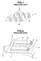
- the core structure of the publication will be briefly described with reference to Figs. 6, 7 and 8 of the accompanying drawings.
- the core structure 100 generally comprises first parallel flat tubes 1 (only two are shown), second parallel flat tubes 2 (only two are shown) which are positioned behind the first tubes 1 and a plurality of corrugated fins 3 (only one is shown) each of which comprises a front part 3a interposed at upper and lower folded edge portions thereof between paired two of the first tubes 1, a rear part 3b interposed at upper and lower folded edge portions thereof between paired two of the second tubes 2 and a center part 3c through which the front and rear parts 3a and 3b are integrally connected.
- the core structure 100 When in use, the core structure 100 is arranged so that the first tubes 1 are in front of the second tubes 2 with respect to a direction of air flow that is produced when an associated motor vehicle runs. (For ease of description, such air flow will be called “running air flow” in the following description.) That is, the first tubes 1 are those through which a refrigerant running in a cooling system of an automotive air conditioner flows to be cooled and the second tubes 2 are those through which an engine cooling water from a water jacket of an associated engine flows to be cooled. Usually, the second tubes 2 are much heated as compared with the first tubes 1.
- the front and rear parts 3a and 3b of the corrugated fins 3 are each formed with plurality of louvers 3a' and 3b' for improving heat radiation effect of the core structure 100.
- each louver 3e comprises a fully raised elongate flat portion 3h which is parallel with a major flat portion of the center part 3c. Due to provision of the parallel louvers 3e, a heat transfer between the first and second tubes 1 and 2, particularly the heat transfer from the highly heated second tubes 2 toward the less heated first tubes 1 is obstructed.
- the parallel louvers 3e are produced by punching a corresponding part (viz., center part 3c) of the corrugated fin 3. With this punching, the corresponding part is cut and partially raised up to produce bridge-like louvers 3e each including the elongate flat portion 3h and two rectangular supporting portions 3i. Due to the nature of the punching, upon punching, portions which are to be formed into the rectangular supporting portions 3i are considerably expanded. Thus, if the supporting portions 3i are positioned extremely close to folded edge portions 3j of the corrugated fin 3 that are also considerably expanded, cracks 3k tend to appear at the bent portions 3j as is seen from Fig. 8. Thus, hitherto, it has been difficult to provide the parallel louvers 3e with a sufficient length "L1". Of course, a satisfied heat transfer obstruction is not expected when the parallel louvers 3e fail to have a sufficient length "L1".
- a core structure of an integral heat-exchanger which comprises at least two first tubes which extend in parallel with each other; at least two second tubes which extend in parallel with each other, the second tubes being juxtaposed with the first tubes; and a corrugated fin including a first part which is interposed at upper and lower folded edge portions thereof between the first tubes, a second part which is interposed at upper and lower folded edge portions between the second tubes and a third part through which the first and second parts are integrally connected, the third part of the corrugated fin being formed with louvers which extend in a direction perpendicular to the upper and lower folded edge portions of the first and second parts, each of the louvers being of a half-louver type including an elongate flat portion which is bent up or down along a longer edge thereof from a major portion of the third part and two generally triangular supporting portions which support longitudinal ends of the elongate flat portion from the major portion.
- a core structure of an integral heat-exchanger which comprises at least two flat first tubes which extend in parallel with each other; at least two flat second tubes which extend in parallel with each other, the second tubes being juxtaposed with the first tubes; a corrugated fin including a first part which is interposed at upper and lower folded edge portions thereof between the first tubes, a second part which is interposed at upper and lower folded edge portions thereof between the second tubes and a third part through which the first and second parts are integrally connected; the first and second parts of the corrugated fin being formed with louvers which extend in a direction perpendicular to the upper and lower folded edge portions of the first and second parts, and the third part of the corrugated fin being formed with louvers which extend in a direction perpendicular to the upper and lower folded edge portions of the first and second parts, each of the louvers being of a half-louver type including an elongate flat portion which is bent up or down along a longer edge thereof from a major portion
- FIG. 1 to 3 there is shown a core structure 100A of an integral heat-exchanger, which is a first embodiment of the present invention.
- the core structure 100A comprises first parallel flat tubes 11 (only two are shown), second parallel flat tubes 12 (only two are shown) which are positioned behind the first tubes 11 and a plurality of corrugated fins 13 (only one is shown) each of which comprises a front part 13a interposed at upper and lower folded edge portions thereof between paired two of the first tubes 11, a rear part 13b interposed at upper and lower folded edge portions thereof between paired two of the second tubes 12 and a center part 13c through which the front and rear parts 13a and 13b are integrally connected.
- the first tubes 11 are positioned in front of the second tubes 12 with respect to the running air flow.
- the first tubes 11 are those through which a refrigerant running in a cooling system of an automotive air conditioner flows and the second tubes 12 are those through which an engine cooling water from a water jacket of an associated engine flows.
- the second tubes 12 are much heated as compared with the first tubes 11.
- the first and second tubes 11 and 12 are the same in shape and size, and the front and rear parts 13a and 13b of each corrugated fin 13 are the same in size.
- the first and second tubes 11 and 12 are each constructed of an aluminum plate. As shown, each tube 11 or 12 is formed with rounded front and rear edges 11a and 11a' (or 12a and 12a'). The thickness of each tube 11 or 12 is about 1.7 mm.
- the corrugated fins 13 are each constructed of an aluminum plate. Each corrugated fin 13 has an upper group of folded edge portions which are welded to inner surfaces 11b and 12b of the upper ones of the first and second tubes 11 and 12 and a lower group of folded edge portions which are welded to inner surfaces 11b' and 12b' of the lower ones of the first and second tubes 11 and 12.
- each corrugated fin 13 are each formed with a plurality of louvers 13d or 13e whose pitch is about 1 mm.
- the louvers 13d and 13e extend in a direction perpendicular to the direction in which the running air flow advances, and the louvers 13d and 13e have each both ends terminating at positions near the first and second tubes 11 and 12.
- the number of the louvers 13d of the front part 13a is the same as those of the louvers 13e of the rear part 13b.
- the front and rear parts 13a and 13b are symmetric with respect to an imaginary plane "IP" which perpendicularly passes through a center line of the corrugated fin 13.
- the center part 13c of the corrugated fin 13 is formed with first and second half-type louvers 15h and 15i which are arranged in front of and behind the imaginary plane "IP".
- the first louver 15h is bent downward from a major flat portion of the center part 13c of the corrugated fin 13, while the second louver 15i is bent upward from the major flat portion.
- the first and second louvers 15h and 15i are at the same angles " ⁇ " with the major flat portion of the center part 13c. However, if desired, the angles may be different.
- the length of the first and second louvers 15h and 15i is substantially the same as that of the louvers 13d and 13e of the front and rear parts 13a and 13b.
- the first and second louvers 15h and 15i can have a sufficient length "L2" (see Fig. 3) for obtaining a satisfied obstruction of the heat transfer between the first and second tubes 11 and 12 for the reason which will be described in the following.
- the first and second louvers 15h and 15i are produced by punching a corresponding part (viz., center part 13c) of the corrugated fins 13. With this punching, the corresponding part is cut and partially raised up from the major flat potion of the center part 13c.
- each of the first and second louvers 15h and 15i thus produced comprises an elongate flat portion 20 which is bent downward or upward along one longer edge from the major flat portion of the center part 13c of the corrugated fin 13 and two generally triangular supporting portions 22 which support longitudinal ends of the elongate flat portion 20 from the major flat portion.
- the two supporting portions 22 are produced by being considerably expanded.
- the size of each triangular supporting portion 22 is generally half of that of the rectangular supporting portion 3i of the related art of Fig.
- the supporting portions 22 can be positioned considerably close to the folded edge portions 15j of the corrugated fin 13, which means permission of elongation, viz., sufficient length "L2", of the first and second louvers 15h and 15i.
- the refrigerant from the cooling system of the air conditioner is led into the first tubes 11 and the cooling water from the water jacket of the associated engine is led into the second tubes 12.
- the heat of the refrigerant and water is transferred to the corrugated fins 13 from the first and second tubes 11 and 12 and radiated to the outside air from the fins 13. Due to provision of the louvers 13d and 13e on the fins 13, heat radiation surface of the fins 13 is increased and thus the heat radiation from the fins 13 is effectively made.
- the core structure 100A receives the running air flow, the heat radiation is much effectively carried out.
- the heat transfer between the front and rear parts 13a and 13b of the fin 13 is obstructed or at least minimized.
- the first and second half-type louvers 15h and 15i have a sufficient length "L2”
- the heat transfer obstruction is effectively made.
- the first and second half-type louvers 15h and 15i are constructed to smoothly introduce and run out the running air flow, and thus provision of such louvers 15h and 15i does not induce an increase in air flow resistance of the core structure 100A.
- a test has revealed that the heat transfer obstruction made by the louvers 15h and 15i is larger than that of the parallel louvers 3e of the related art (see Fig. 8) by about 50%.
- FIG. 4 there is shown a core structure 100B of an integral heat-exchanger, which is a second embodiment of the present invention.
- the second embodiment 100B is similar to the above-mentioned first embodiment 100A, only parts or portions which are different from those of the first embodiment 100A will be described in detail in the following.
- a center part 113c is different from the center part 13c of the first embodiment 100A.
- the center part 113c of the corrugated fin 13 is formed with first, second, third and fourth half-type louvers 15s, 15p, 15r and 15t which are arranged in order with respect to the direction of the running air flow.
- a unit including the first and second louvers 15s and 15p and the other unit including the third and fourth louvers 15r and 15t are symmetrically arranged with respect to the imaginary plane "IP". More specifically, the first and second louvers 15s and 15p are substantially the same as the above-mentioned first and second louvers 15h and 15i of the first embodiment 100A, while the third and fourth louvers 15r and 15t are reversed in construction to the first and second louvers 15s and 15p with respect to the imaginary plane "IP".
- the first, second, third and fourth half-type louvers 15s, 15p, 15r and 15t can each have a sufficient length "L2".
- the heat transfer between the front and rear parts 13a and 13b of the corrugated fin 13 is effectively obstructed.
- the symmetric arrangement between the unit of first and second louvers 15h and 15i and the other unit of third and fourth louvers 15r and 15t reduces or at least minimizes undesired curving of the corrugated fin 13 which would be produced upon punching.
- louvers 13d and 13e formed in the front and rear parts 13a and 13b of the fin 13 may be of a parallel type which, as is seen from Fig. 8, comprises a fully raised elongate flat portion 3h and two generally rectangular supporting portions 3i.
Landscapes
- Engineering & Computer Science (AREA)
- Physics & Mathematics (AREA)
- Thermal Sciences (AREA)
- Mechanical Engineering (AREA)
- General Engineering & Computer Science (AREA)
- Geometry (AREA)
- Heat-Exchange Devices With Radiators And Conduit Assemblies (AREA)
Applications Claiming Priority (2)
| Application Number | Priority Date | Filing Date | Title |
|---|---|---|---|
| JP2001075469 | 2001-03-16 | ||
| JP2001075469A JP2002277180A (ja) | 2001-03-16 | 2001-03-16 | 一体型熱交換器のコア部構造 |
Publications (2)
| Publication Number | Publication Date |
|---|---|
| EP1241424A2 true EP1241424A2 (fr) | 2002-09-18 |
| EP1241424A3 EP1241424A3 (fr) | 2006-04-26 |
Family
ID=18932544
Family Applications (1)
| Application Number | Title | Priority Date | Filing Date |
|---|---|---|---|
| EP02005769A Ceased EP1241424A3 (fr) | 2001-03-16 | 2002-03-13 | Structure de bloc d'échangeur de chaleur combiné |
Country Status (3)
| Country | Link |
|---|---|
| US (2) | US6957694B2 (fr) |
| EP (1) | EP1241424A3 (fr) |
| JP (1) | JP2002277180A (fr) |
Cited By (8)
| Publication number | Priority date | Publication date | Assignee | Title |
|---|---|---|---|---|
| WO2003050468A1 (fr) * | 2001-12-12 | 2003-06-19 | Modine Manufacturing Company | Ailette fendue pour echangeur de chaleur |
| EP1647341A2 (fr) | 2004-10-14 | 2006-04-19 | Behr GmbH & Co. KG | Méthode de fabrication des ailettes ondulées et bloc d'échangeur de chaleur comprenant des ailettes ondulées produit en applicant cette méthode |
| EP1712865A1 (fr) * | 2005-04-14 | 2006-10-18 | Calsonic Kansei Corporation | Ailette ondulée pour des échangeurs de chaleur assemblés intégralement |
| DE102007036308A1 (de) * | 2007-07-31 | 2009-02-05 | Behr Gmbh & Co. Kg | Rippe für einen Wärmetauscher |
| EP1729078A3 (fr) * | 2005-05-26 | 2012-11-07 | LG Electronics Inc. | Échangeur de chaleur pour séchoir et séchoir de type à condensation utilisant celui-ci |
| EP2096397A3 (fr) * | 2007-10-08 | 2013-07-17 | Behr GmbH & Co. KG | Ailette pour un échangeur thermique et procédé de fabrication |
| FR2991034A1 (fr) * | 2012-05-25 | 2013-11-29 | Valeo Systemes Thermiques | Intercalaire pour echangeur thermique et echangeur thermique associe |
| EP2653819A4 (fr) * | 2011-01-21 | 2014-07-02 | Daikin Ind Ltd | Échangeur de chaleur et climatiseur |
Families Citing this family (13)
| Publication number | Priority date | Publication date | Assignee | Title |
|---|---|---|---|---|
| KR20040014039A (ko) * | 2002-08-09 | 2004-02-14 | 한라공조주식회사 | 방열휜과 이를 이용한 열교환기 |
| DE102004012796A1 (de) * | 2003-03-19 | 2004-11-11 | Denso Corp., Kariya | Wärmetauscher und Wärmeübertragungselement mit symmetrischen Winkelabschnitten |
| US20070240865A1 (en) * | 2006-04-13 | 2007-10-18 | Zhang Chao A | High performance louvered fin for heat exchanger |
| US20080142202A1 (en) * | 2006-12-15 | 2008-06-19 | Valeo, Inc. | High strength fin louver design |
| US20090084131A1 (en) * | 2007-10-01 | 2009-04-02 | Nordyne Inc. | Air Conditioning Units with Modular Heat Exchangers, Inventories, Buildings, and Methods |
| US8196646B2 (en) * | 2008-12-15 | 2012-06-12 | Delphi Technologies, Inc. | Heat exchanger assembly |
| DE102011007784A1 (de) * | 2011-04-20 | 2012-10-25 | Behr Gmbh & Co. Kg | Kondensator |
| CN104937364B (zh) | 2013-01-28 | 2019-03-08 | 开利公司 | 具有歧管组件的多管束换热单元 |
| ES2627555T3 (es) * | 2013-02-13 | 2017-07-28 | Carrier Corporation | Intercambiador de calor con tubos aplanados y múltiples bancos |
| US10337799B2 (en) * | 2013-11-25 | 2019-07-02 | Carrier Corporation | Dual duty microchannel heat exchanger |
| CN107218822B (zh) * | 2016-03-21 | 2019-04-19 | 丹佛斯微通道换热器(嘉兴)有限公司 | 换热器和空调系统 |
| DE102016210159A1 (de) * | 2016-06-08 | 2017-12-14 | Mahle International Gmbh | Rippenelement für einen Wärmeübertrager |
| CN110307745A (zh) * | 2019-07-15 | 2019-10-08 | 浙江工业大学 | 一种带犁形微凸的板翅式换热器翅片 |
Citations (1)
| Publication number | Priority date | Publication date | Assignee | Title |
|---|---|---|---|---|
| JPS649783A (en) | 1987-07-01 | 1989-01-13 | Toyo Ink Mfg Co | Thermal recording method |
Family Cites Families (22)
| Publication number | Priority date | Publication date | Assignee | Title |
|---|---|---|---|---|
| US3003749A (en) * | 1957-09-09 | 1961-10-10 | Modine Mfg Co | Automotive strip serpentine fin |
| US3265127A (en) * | 1963-10-21 | 1966-08-09 | Ford Motor Co | Heat exchange element |
| US4328861A (en) * | 1979-06-21 | 1982-05-11 | Borg-Warner Corporation | Louvred fins for heat exchangers |
| JPS6012088U (ja) * | 1983-06-30 | 1985-01-26 | カルソニックカンセイ株式会社 | 熱交換器 |
| US4693307A (en) * | 1985-09-16 | 1987-09-15 | General Motors Corporation | Tube and fin heat exchanger with hybrid heat transfer fin arrangement |
| JPS63163785A (ja) * | 1986-12-25 | 1988-07-07 | Nippon Denso Co Ltd | 熱交換器 |
| JP2786702B2 (ja) * | 1989-12-07 | 1998-08-13 | 昭和アルミニウム株式会社 | 複式一体型熱交換器 |
| US5289874A (en) * | 1993-06-28 | 1994-03-01 | General Motors Corporation | Heat exchanger with laterally displaced louvered fin sections |
| US5992514A (en) * | 1995-11-13 | 1999-11-30 | Denso Corporation | Heat exchanger having several exchanging portions |
| JP3630201B2 (ja) | 1996-06-19 | 2005-03-16 | カルソニックカンセイ株式会社 | 一体型熱交換器 |
| AU729629B2 (en) * | 1996-08-12 | 2001-02-08 | Calsonic Corporation | Integral-type heat exchanger |
| US5669438A (en) * | 1996-08-30 | 1997-09-23 | General Motors Corporation | Corrugated cooling fin with louvers |
| FR2757259B1 (fr) * | 1996-12-18 | 1999-03-05 | Valeo Thermique Moteur Sa | Ailette metallique perfectionnee pour echangeur de chaleur, notamment pour vehicule automobile |
| US6209628B1 (en) * | 1997-03-17 | 2001-04-03 | Denso Corporation | Heat exchanger having several heat exchanging portions |
| JP4019113B2 (ja) * | 1997-11-13 | 2007-12-12 | 株式会社ティラド | 一体型熱交換器のフィンとその製造方法 |
| JPH11294984A (ja) * | 1998-04-09 | 1999-10-29 | Zexel:Kk | 並設一体型熱交換器 |
| FR2785978B1 (fr) * | 1998-11-16 | 2001-03-30 | Valeo Thermique Moteur Sa | Echangeur de chaleur multiple a intercalaires communs |
| JP4117429B2 (ja) * | 1999-02-01 | 2008-07-16 | 株式会社デンソー | 熱交換器用フィン |
| EP1167909A3 (fr) * | 2000-02-08 | 2005-10-12 | Calsonic Kansei Corporation | Structure de bloc d'échangeur de chaleur combiné |
| EP1193460A2 (fr) * | 2000-09-29 | 2002-04-03 | Calsonic Kansei Corporation | Structure de bloc d'échangeur de chaleur combiné |
| US20030075307A1 (en) * | 2001-10-22 | 2003-04-24 | Heatcraft, Inc. | Exchanger of thermal energy with multiple cores and a thermal barrier |
| US6805193B2 (en) * | 2002-01-24 | 2004-10-19 | Valeo, Inc. | Fin louver design for heat exchanger |
-
2001
- 2001-03-16 JP JP2001075469A patent/JP2002277180A/ja active Pending
-
2002
- 2002-03-13 EP EP02005769A patent/EP1241424A3/fr not_active Ceased
- 2002-03-15 US US10/097,422 patent/US6957694B2/en not_active Expired - Fee Related
-
2005
- 2005-09-26 US US11/234,139 patent/US7117933B2/en not_active Expired - Fee Related
Patent Citations (1)
| Publication number | Priority date | Publication date | Assignee | Title |
|---|---|---|---|---|
| JPS649783A (en) | 1987-07-01 | 1989-01-13 | Toyo Ink Mfg Co | Thermal recording method |
Cited By (12)
| Publication number | Priority date | Publication date | Assignee | Title |
|---|---|---|---|---|
| WO2003050468A1 (fr) * | 2001-12-12 | 2003-06-19 | Modine Manufacturing Company | Ailette fendue pour echangeur de chaleur |
| EP1647341A2 (fr) | 2004-10-14 | 2006-04-19 | Behr GmbH & Co. KG | Méthode de fabrication des ailettes ondulées et bloc d'échangeur de chaleur comprenant des ailettes ondulées produit en applicant cette méthode |
| DE102004050160A1 (de) * | 2004-10-14 | 2006-04-27 | Behr Gmbh & Co. Kg | Verfahren zum Herstellen einer Wellrippe und Wärmeübertragerblock mit nach dem Verfahren hergestellten Wellrippen |
| EP1712865A1 (fr) * | 2005-04-14 | 2006-10-18 | Calsonic Kansei Corporation | Ailette ondulée pour des échangeurs de chaleur assemblés intégralement |
| US7478669B2 (en) | 2005-04-14 | 2009-01-20 | Calsonic Kansei Corporation | Corrugated fin for integrally assembled heat exchangers |
| EP1729078A3 (fr) * | 2005-05-26 | 2012-11-07 | LG Electronics Inc. | Échangeur de chaleur pour séchoir et séchoir de type à condensation utilisant celui-ci |
| DE102007036308A1 (de) * | 2007-07-31 | 2009-02-05 | Behr Gmbh & Co. Kg | Rippe für einen Wärmetauscher |
| EP2096397A3 (fr) * | 2007-10-08 | 2013-07-17 | Behr GmbH & Co. KG | Ailette pour un échangeur thermique et procédé de fabrication |
| EP2653819A4 (fr) * | 2011-01-21 | 2014-07-02 | Daikin Ind Ltd | Échangeur de chaleur et climatiseur |
| AU2012208127B2 (en) * | 2011-01-21 | 2015-05-21 | Daikin Industries, Ltd. | Heat exchanger and air conditioner |
| US9316446B2 (en) | 2011-01-21 | 2016-04-19 | Daikin Industries, Ltd. | Heat exchanger and air conditioner |
| FR2991034A1 (fr) * | 2012-05-25 | 2013-11-29 | Valeo Systemes Thermiques | Intercalaire pour echangeur thermique et echangeur thermique associe |
Also Published As
| Publication number | Publication date |
|---|---|
| US7117933B2 (en) | 2006-10-10 |
| EP1241424A3 (fr) | 2006-04-26 |
| US6957694B2 (en) | 2005-10-25 |
| JP2002277180A (ja) | 2002-09-25 |
| US20020129929A1 (en) | 2002-09-19 |
| US20060016585A1 (en) | 2006-01-26 |
Similar Documents
| Publication | Publication Date | Title |
|---|---|---|
| EP1241424A2 (fr) | Structure de bloc d'échangeur de chaleur combiné | |
| US6889757B2 (en) | Core structure of integral heat-exchanger | |
| EP1231448B1 (fr) | Echangeur de chaleur | |
| JP4117429B2 (ja) | 熱交換器用フィン | |
| US20070287334A1 (en) | Flat tube adapted for heat exchanger | |
| JPH05196383A (ja) | コルゲートフィン型熱交換器 | |
| US20020189799A1 (en) | Heat exchanger | |
| JP2001194082A (ja) | 熱交換器のための連続複合フィン | |
| CN101010555A (zh) | 热交换器装置 | |
| US7287577B2 (en) | Heat exchanger | |
| JP3903888B2 (ja) | 熱交換器 | |
| JP2007178015A (ja) | 熱交換器 | |
| JP2001147087A (ja) | フィンチューブ型熱交換器 | |
| JP4173959B2 (ja) | 一体型熱交換器のコア部構造 | |
| JP2000234882A (ja) | 熱交換器 | |
| JP4415712B2 (ja) | 熱交換器 | |
| JP4626422B2 (ja) | フィンチューブ型熱交換器 | |
| JPH11281279A (ja) | 熱交換器 | |
| CN213984664U (zh) | 换热组件 | |
| JP6599023B2 (ja) | 熱交換器、熱交換器の製造方法及びフィン組立品 | |
| JPH1137683A (ja) | 熱交換器 | |
| JP3133057B2 (ja) | 熱交換器用コルゲートフィン | |
| JPH066954U (ja) | 空調用熱交換器 | |
| EP1193460A2 (fr) | Structure de bloc d'échangeur de chaleur combiné | |
| JPH0560483A (ja) | オイルクーラ |
Legal Events
| Date | Code | Title | Description |
|---|---|---|---|
| PUAI | Public reference made under article 153(3) epc to a published international application that has entered the european phase |
Free format text: ORIGINAL CODE: 0009012 |
|
| 17P | Request for examination filed |
Effective date: 20020313 |
|
| AK | Designated contracting states |
Kind code of ref document: A2 Designated state(s): AT BE CH CY DE DK ES FI FR GB GR IE IT LI LU MC NL PT SE TR |
|
| AX | Request for extension of the european patent |
Free format text: AL;LT;LV;MK;RO;SI |
|
| PUAL | Search report despatched |
Free format text: ORIGINAL CODE: 0009013 |
|
| AK | Designated contracting states |
Kind code of ref document: A3 Designated state(s): AT BE CH CY DE DK ES FI FR GB GR IE IT LI LU MC NL PT SE TR |
|
| AX | Request for extension of the european patent |
Extension state: AL LT LV MK RO SI |
|
| 17Q | First examination report despatched |
Effective date: 20061002 |
|
| AKX | Designation fees paid |
Designated state(s): DE FR GB |
|
| STAA | Information on the status of an ep patent application or granted ep patent |
Free format text: STATUS: THE APPLICATION HAS BEEN REFUSED |
|
| 18R | Application refused |
Effective date: 20090215 |