EP1647631A2 - Spritzgerät, insbesondere zum Verspritzen von Bitumenemulsionen - Google Patents
Spritzgerät, insbesondere zum Verspritzen von Bitumenemulsionen Download PDFInfo
- Publication number
- EP1647631A2 EP1647631A2 EP05109494A EP05109494A EP1647631A2 EP 1647631 A2 EP1647631 A2 EP 1647631A2 EP 05109494 A EP05109494 A EP 05109494A EP 05109494 A EP05109494 A EP 05109494A EP 1647631 A2 EP1647631 A2 EP 1647631A2
- Authority
- EP
- European Patent Office
- Prior art keywords
- sprayer
- frame
- spraying
- operator
- tank
- Prior art date
- Legal status (The legal status is an assumption and is not a legal conclusion. Google has not performed a legal analysis and makes no representation as to the accuracy of the status listed.)
- Withdrawn
Links
Images


Classifications
-
- E—FIXED CONSTRUCTIONS
- E01—CONSTRUCTION OF ROADS, RAILWAYS, OR BRIDGES
- E01C—CONSTRUCTION OF, OR SURFACES FOR, ROADS, SPORTS GROUNDS, OR THE LIKE; MACHINES OR AUXILIARY TOOLS FOR CONSTRUCTION OR REPAIR
- E01C19/00—Machines, tools or auxiliary devices for preparing or distributing paving materials, for working the placed materials, or for forming, consolidating, or finishing the paving
- E01C19/12—Machines, tools or auxiliary devices for preparing or distributing paving materials, for working the placed materials, or for forming, consolidating, or finishing the paving for distributing granular or liquid materials
- E01C19/16—Machines, tools or auxiliary devices for preparing or distributing paving materials, for working the placed materials, or for forming, consolidating, or finishing the paving for distributing granular or liquid materials for applying or spreading liquid materials, e.g. bitumen slurries
- E01C19/17—Application by spraying or throwing
- E01C19/174—Apparatus with pump-discharge
-
- B—PERFORMING OPERATIONS; TRANSPORTING
- B05—SPRAYING OR ATOMISING IN GENERAL; APPLYING FLUENT MATERIALS TO SURFACES, IN GENERAL
- B05B—SPRAYING APPARATUS; ATOMISING APPARATUS; NOZZLES
- B05B15/00—Details of spraying plant or spraying apparatus not otherwise provided for; Accessories
- B05B15/40—Filters located upstream of the spraying outlets
-
- B—PERFORMING OPERATIONS; TRANSPORTING
- B05—SPRAYING OR ATOMISING IN GENERAL; APPLYING FLUENT MATERIALS TO SURFACES, IN GENERAL
- B05B—SPRAYING APPARATUS; ATOMISING APPARATUS; NOZZLES
- B05B15/00—Details of spraying plant or spraying apparatus not otherwise provided for; Accessories
- B05B15/50—Arrangements for cleaning; Arrangements for preventing deposits, drying-out or blockage; Arrangements for detecting improper discharge caused by the presence of foreign matter
- B05B15/55—Arrangements for cleaning; Arrangements for preventing deposits, drying-out or blockage; Arrangements for detecting improper discharge caused by the presence of foreign matter using cleaning fluids
-
- B—PERFORMING OPERATIONS; TRANSPORTING
- B05—SPRAYING OR ATOMISING IN GENERAL; APPLYING FLUENT MATERIALS TO SURFACES, IN GENERAL
- B05B—SPRAYING APPARATUS; ATOMISING APPARATUS; NOZZLES
- B05B15/00—Details of spraying plant or spraying apparatus not otherwise provided for; Accessories
- B05B15/60—Arrangements for mounting, supporting or holding spraying apparatus
- B05B15/62—Arrangements for supporting spraying apparatus, e.g. suction cups
- B05B15/628—Arrangements for supporting spraying apparatus, e.g. suction cups of variable length
-
- B—PERFORMING OPERATIONS; TRANSPORTING
- B05—SPRAYING OR ATOMISING IN GENERAL; APPLYING FLUENT MATERIALS TO SURFACES, IN GENERAL
- B05B—SPRAYING APPARATUS; ATOMISING APPARATUS; NOZZLES
- B05B9/00—Spraying apparatus for discharge of liquids or other fluent material, without essentially mixing with gas or vapour
- B05B9/007—At least a part of the apparatus, e.g. a container, being provided with means, e.g. wheels, for allowing its displacement relative to the ground
-
- B—PERFORMING OPERATIONS; TRANSPORTING
- B05—SPRAYING OR ATOMISING IN GENERAL; APPLYING FLUENT MATERIALS TO SURFACES, IN GENERAL
- B05B—SPRAYING APPARATUS; ATOMISING APPARATUS; NOZZLES
- B05B9/00—Spraying apparatus for discharge of liquids or other fluent material, without essentially mixing with gas or vapour
- B05B9/03—Spraying apparatus for discharge of liquids or other fluent material, without essentially mixing with gas or vapour characterised by means for supplying liquid or other fluent material
- B05B9/04—Spraying apparatus for discharge of liquids or other fluent material, without essentially mixing with gas or vapour characterised by means for supplying liquid or other fluent material with pressurised or compressible container; with pump
- B05B9/0403—Spraying apparatus for discharge of liquids or other fluent material, without essentially mixing with gas or vapour characterised by means for supplying liquid or other fluent material with pressurised or compressible container; with pump with pumps for liquids or other fluent material
-
- B—PERFORMING OPERATIONS; TRANSPORTING
- B05—SPRAYING OR ATOMISING IN GENERAL; APPLYING FLUENT MATERIALS TO SURFACES, IN GENERAL
- B05B—SPRAYING APPARATUS; ATOMISING APPARATUS; NOZZLES
- B05B9/00—Spraying apparatus for discharge of liquids or other fluent material, without essentially mixing with gas or vapour
- B05B9/01—Spray pistols, discharge devices
Definitions
- the invention concerns a sprayer particularly suitable for spraying bitumen emulsions when asphalting surfaces.
- Such emulsion is usually sprayed by means of spraying machines that substantially comprise a frame installed on wheels that supports a drum containing the bitumen emulsion and a pumping unit that draws the emulsion from the drum and conveys it to a spray lance that is held by the operator.
- the sprayer is guided and the spray lance is manoeuvred manually by one or two operators.
- the spraying machines described are particularly suitable for treating surfaces that are not too large since, being manual and controlled by the operator, they are not economic to use on wide surfaces.
- the spraying system comprises a frame that can be loaded on a motor vehicle and supports a tank containing the bitumen emulsion to be sprayed, and a spraying unit constituted by an hydraulically controlled spraying bar, fed by a pumping unit that draws the bitumen emulsion from the tank and conveys it to the spraying bar.
- the two types of spraying machines described are therefore destined to different sectors of application, in particular the manual sprayers provided with wheels are especially suited to carry out spraying work on limited surfaces, while the hydraulic spraying systems that can be loaded on motor vehicles are especially suitable for treating wide surfaces. They can also be autonomously transported over long distances.
- a first drawback that is common to both sprayers is represented by the need, for the user, to have at least one manual wheeled sprayer and at least one hydraulic spraying system, either of them being suitable for use according to the different type of application.
- Another drawback is due to the fact that, since the two machines are not interchangeable, the user is forced to schedule the work to be carried out very carefully, in such a way as to avoid planning for the same period and in different places works that must be done with the same sprayer, if only one sprayer per type is available.
- a further drawback of manual sprayers with wheels is represented by the fact that it is difficult to load on them the tank containing the bitumen emulsion to be sprayed.
- the tank When the tank has been placed in the cradle, it must be further rotated by the operator, who places the access hole in the highest position, in such a way as to ensure that the suction pipe can be inserted without pouring the emulsion onto the ground due to gravity.
- a further drawback of said known manual sprayers is constituted by the fact that during the periods of inactivity the bitumen emulsion present on the nozzle of the spray lance and on the filter of the suction pipe inserted in the tank tends to dry and clog the passage holes.
- a further specific drawback of the hydraulic spraying means that can be loaded on motor vehicles is their high cost.
- the present invention intends to overcome the limitations and drawbacks described above.
- a further aim of the invention is to produce a sprayer that makes it possible to carry out the same spraying treatments that can be performed with the hydraulic spraying systems that can be loaded on motor vehicles, with no need to make considerable investments.
- a further aim of the invention is to produce a sprayer provided with spraying means that in rest position are shorter than the spraying means of the known sprayers.
- the coupling means comprise one or more pins belonging to the frame and one or more holes belonging to the support structure, wherein each one of said pins is suited to fit into one the corresponding holes.
- the holes instead of being made in the support structure, may be made in the frame and therefore the pins will be made in the support structure.
- the support structure of the pumping unit is also provided with handles to enable positioning of the pumping unit on the flatbed of a vehicle, preferably but not necessarily a truck, a van or a similar vehicle.
- An unwinder-winder unit is provided to support the suction pipe, said unwinder-winder unit being of the known type available on the market and being applied to the frame of the sprayer through a rotation pin that allows it to be directed in such a way as to follow the direction in which the delivery pipe is unwound and automatically rewound when the operator manoeuvres the spraying means.
- the sprayer is also equipped with a solvent liquid container, supported by the frame, which houses the filter positioned at the end of the pipe drawing the emulsion from the tank, as well as the spraying means nozzle.
- the spraying means are constituted by a rigid rod and a rigid pipe connected to the delivery pipe of the bitumen emulsion to be sprayed, telescopically coupled to each other.
- the sprayer frame is also provided with supporting means suited to support the spraying means when they are not used and are in rest position.
- the sprayer subject of the invention being provided with a removable pumping unit, ensures greater flexibility of use, since the user can move the pumping unit from the sprayer frame to the flatbed of a vehicle according to his/her preferences and needs. In this way, the sprayer changes from a manual rotated sprayer into a self-propelled sprayer.
- an unwinder-winder unit keeps the delivery pipe constantly stretched, prevents it from touching the ground and from getting dirty with the bitumen emulsion and makes it easier for the operator to manoeuvre the spraying means.
- the presence of the container of solvents for the bitumen emulsion allows the filter and the spray nozzle contained therein to be kept clean, thus preventing them from getting clogged in case of long periods of inactivity.
- the telescopic configuration of the spraying means makes it possible to reduce their size and improve the manoeuvrability of the sprayer, mainly during transport in conditions of inactivity, when the spraying means are supported by the apposite supporting means fixed to the frame.
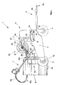
- the sprayer subject of the invention is represented in its whole and in different views in the Figures from 1 to 3, where it is indicated as a whole by 1.
- the pumping unit 5 comprises a suction pipe 6a that is connected to the tank R for drawing the emulsion and a delivery pipe 6b connected to means 7 for spraying the same bitumen emulsion.
- the frame 2 is also combined with guide means indicated as a whole by 8, which comprise a rod 8a hinged to the frame 2 in correspondence with the rear wheel 4, provided with a handle 8b supplied to be used by the operator O.
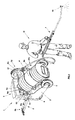
- the pumping unit 5 belongs to a removable support structure 15 that is combined with the frame 2 via coupling means 16 that can be seen in the whole in Figure 6.
- the coupling means 16 comprise four pins 17 belonging to the frame 2 and four holes 18 belonging to the support structure 15, wherein each one of said pins 17 is suited to fit into a corresponding hole 18 .
- the pins instead of belonging to the frame 2, may belong to the support structure 15 and in this case the holes, instead of belonging to the support structure 15, will belong to the frame 2. Furthermore, the pins and holes may be present in a number different from four.
- a split pin 30 is inserted in a transversal through hole 17b present in the end 17a of each pin 17 protruding from the corresponding hole 18.
- the pins 17 are made in such a way as to be coaxial to corresponding cylindrical cores 19 fixed to the frame 2 and having a greater diameter than the pins 17.
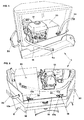
- handles 20 On the outside of the support structure 15 there are handles 20 that can be grasped by the operator to separate the pumping unit 5 from the frame 2 and position it on the flatbed P of a self-propelled vehicle T, as illustrated in Figure 7.
- the tank R containing the bitumen emulsion is housed by supporting means 10 that, as can be observed in particular in Figure 1, comprise a shaped structure 11 for resting the side of the tank R that ends with a lower surface 12 on which the base of the tank R can be placed.
- the shaped structure 11 is provided with a cross shaft 13 for connection to the frame 2, in such a way as to be rotary and facilitate loading of the tank R, which can be carried out by rotatingly overturning it around the shaft 13.
- the pumping unit 5 As regards the pumping unit 5, as shown in particular in Figure 4 it comprises a pump 50 connected to the suction and delivery pipes 6a and 6b, respectively, and combined with power means, in particular an engine 51, suited to set it rotating.
- the power means may be an electric motor.
- the suction pipe 6a with the corresponding filter 28 places the suction opening of the pump 50 in communication with the inside of the tank R and the delivery pipe 6b places the delivery opening of the same pump 50 in communication with the spraying means 7.
- the spraying means 7 comprise, as can be observed in Figures 9 and 10, a rigid rod 40 provided with first holding means 41 at the operator's disposal and a rigid pipe 42 provided at one end with the spray nozzle 36 and at the opposite end with means 43 for coupling to the delivery pipe 6b.
- connection means indicated as a whole by 49 are connected to each other via connection means indicated as a whole by 49.
- connection means 49 allow the rigid rod 40 to be telescopically connected to the rigid pipe 42 and comprise a tubular coupling 45, fixed to the rigid rod 40 via weldings 46, with a longitudinal hole passing through its whole length 47 and slidingly housing the rigid pipe 42.
- Screw means indicated as a whole by 48 and manoeuvrable by the operator allow the rigid pipe 42 to be locked inside the tubular coupling 45 in the desired position.
- the spraying means 7 can be arranged with the rigid rod 40 and the rigid pipe 42 in the position of maximum extension that can be observed in Figure 2 when the sprayer is in operation or in the position of maximum retraction that can be observed in Figure 1 when the spraying means 7 are arranged in rest position supported by the supporting means 9 connected to the frame 2.
- the container 32 is constituted by a prismatic container 33 having two openings 34 and 35 for the passage, respectively, of the filter 28 positioned at the end of the suction pipe 6a and the spray nozzle 36 positioned at the end of the spraying means 7.
- the presence of the solvent liquid L inside the prismatic container 33 allows the filter 28 and the nozzle 36 to remain wet, thus preventing them from getting clogged due to the hardening of the bitumen emulsion during the periods of inactivity of the sprayer.
- the sprayer comprises an unwinder-winder unit 22 for the delivery pipe 6b, combined with said frame 2 and suited to ensure that during spraying the section 21a of said delivery pipe 6b included between the unwinder-winder 22 and the spraying means 7 remains stretched.
- this is of the known type available on the market and comprises a pulley 25 on which the delivery pipe 6b is wound, combined via a first pin 24 with a support bracket 27 supported by the frame 2 of the sprayer.
- the pulley 25 rotates around the first pin 24 and internally is provided with elastic twist means 31 that can be observed in Figure 3, interposed between the pulley 25 and the support bracket 27, in such a way as to obtain an elastic rotation of the pulley 25 around the pin 24.
- the support bracket 27 is connected to the frame 2 via a second pin 29 that defines a vertical rotation axis Y of the bracket 27 and of the unwinder-winder unit 22 in its whole, to follow the movements of the spraying means 7 induced by the movements of the operator.
- the support bracket 27 is also provided with guide rollers 37 facing each other, between which the delivery pipe 6b slides.
- the unwinder-winder unit there are means for locking the elastic twist means 31 that, if desired by the operator, can void the twist effect when the pipe is unwound.
- the operator after loading the tank R on the sprayer, inserts the filter 28 of the suction pipe 6a in the tank R itself and, grasping the handle 8b of the rod 8a, guides the sprayer to the work position.
- a single operator may manoeuvre the sprayer and set it in working position and then, grasping the spraying means, spread the bitumen emulsion onto the ground.
- the pumping unit 5 can be separated from the frame 2 of the sprayer and, as shown in Figure 7, be positioned on the flatbed P of a self-propelled vehicle T on which the tank R containing the bitumen emulsion to be sprayed is also positioned.
- the tank R containing the bitumen emulsion can be larger, depending on the work to be carried out, or there may be more than one tank on the flatbed of the vehicle.
- Two operators provide for separating the pumping unit 5 from the frame 2 and positioning it on the vehicle T; first they remove the split pins 19 associated with the pins 17 and then, grasping the handles 20, they lift the pumping unit 5 from the frame 2 and load it on the flatbed P of the self-propelled vehicle T.
- the suction pipe 6a with the relevant filter 28 positioned at its end is inserted in the tank R, while the spraying means 7 associated with the delivery pipe 6b are grasped by the operator who provides for spraying the emulsion onto the ground.
- the sprayer can be used as a manual wheeled sprayer, but the pumping unit can also be separated from it and loaded on the self-propelled vehicle.
- the presence of the unwinder-winder 22 allows the section 21 a of the delivery pipe 6b included between the unwinder-winder 22 and the spraying means 7 to be constantly stretched, thus preventing the pipe from getting dirty due to contact with the surface on which the bitumen emulsion is sprayed.
- the presence of the container 32 with solvent liquid prevents the drying of the bitumen emulsion present on the filter 28 and on the nozzle 36 of the spraying means 7 during the periods of inactivity of the sprayer, so that they remain efficient and ready to be used when necessary.
- the telescopic configuration of the spraying means 7 allows their length to be reduced, thus reducing also the overall dimensions of the sprayer when said spraying means are in rest position, supported by the supporting means 9. Therefore the sprayer subject of the invention, when combined with any self-propelled vehicle, can also be used as the hydraulic spraying means that can be loaded on motor vehicles.
- the aim to produce a low-cost self-propelled sprayer is thus achieved, by simply installing the pumping unit of the sprayer subject of the invention on the flatbed of the self-propelled vehicle itself.
- the spraying machine subject of the invention may have any shape and size.
- the coupling means that allow the pumping unit to be removably connected to the frame of the spraying machine can be carried out in a different way than described and illustrated.
Landscapes
- Engineering & Computer Science (AREA)
- Architecture (AREA)
- Civil Engineering (AREA)
- Structural Engineering (AREA)
- Road Paving Machines (AREA)
- Catching Or Destruction (AREA)
Applications Claiming Priority (2)
| Application Number | Priority Date | Filing Date | Title |
|---|---|---|---|
| ITVI20040241 ITVI20040241A1 (it) | 2004-10-12 | 2004-10-12 | Spruzzatrice particolarmente adatta per la spruzzatura di emulsioni bituminose |
| ITVI20040245 ITVI20040245A1 (it) | 2004-10-13 | 2004-10-13 | Spruzzatrice perfezionata per emulsioni bituminose |
Publications (2)
| Publication Number | Publication Date |
|---|---|
| EP1647631A2 true EP1647631A2 (de) | 2006-04-19 |
| EP1647631A3 EP1647631A3 (de) | 2006-06-14 |
Family
ID=35672753
Family Applications (1)
| Application Number | Title | Priority Date | Filing Date |
|---|---|---|---|
| EP05109494A Withdrawn EP1647631A3 (de) | 2004-10-12 | 2005-10-12 | Spritzgerät, insbesondere zum Verspritzen von Bitumenemulsionen |
Country Status (1)
| Country | Link |
|---|---|
| EP (1) | EP1647631A3 (de) |
Cited By (4)
| Publication number | Priority date | Publication date | Assignee | Title |
|---|---|---|---|---|
| FR2945968A1 (fr) * | 2009-05-27 | 2010-12-03 | Jetline | Dispositif destine a eviter le bouchage de la buse par sechage de la peinture et autres produits dans un pistolet de pulverisation monte sur les machines de marquage des routes |
| CN103711061A (zh) * | 2013-12-10 | 2014-04-09 | 柳州博泽科技有限公司 | 一种新型乳化沥青喷洒装置 |
| CN106192681A (zh) * | 2016-08-17 | 2016-12-07 | 钟文华 | 一种高速公路用透层沥青快速喷洒装置 |
| EP3714986A1 (de) * | 2019-03-28 | 2020-09-30 | Exel Industries | Rohr und ansaugeinheit für flüssige farbe sowie herstellungsverfahren eines solchen rohrs |
Family Cites Families (6)
| Publication number | Priority date | Publication date | Assignee | Title |
|---|---|---|---|---|
| GB106125A (en) * | 1916-05-08 | 1917-05-08 | Henry Ballans Dewhurst | Improvements in or connected with Tar Spraying Machines or Boilers and such like. |
| GB425444A (en) * | 1934-07-23 | 1935-03-14 | Frank Coleman | Improvements in or relating to apparatus for surface-spraying roads, paths and like surfaces |
| FR802482A (fr) * | 1936-02-29 | 1936-09-05 | Ammann | Arroseuse pour matériaux de construction liquides |
| CH364183A (de) * | 1958-11-24 | 1962-08-31 | Gerber Werner | Teer- und Kaltasphaltspritz- und Fasstransportkarren |
| GB989355A (en) * | 1962-01-22 | 1965-04-14 | Autogen Endress A G | Improvements in or relating to building contractors' machinery |
| DE3125206A1 (de) * | 1981-06-26 | 1983-01-13 | GEKO-Apparatebau GmbH, 7750 Konstanz | Spritzgeraet insbesondere zum verspritzen von dickfluessigen medien |
-
2005
- 2005-10-12 EP EP05109494A patent/EP1647631A3/de not_active Withdrawn
Cited By (6)
| Publication number | Priority date | Publication date | Assignee | Title |
|---|---|---|---|---|
| FR2945968A1 (fr) * | 2009-05-27 | 2010-12-03 | Jetline | Dispositif destine a eviter le bouchage de la buse par sechage de la peinture et autres produits dans un pistolet de pulverisation monte sur les machines de marquage des routes |
| CN103711061A (zh) * | 2013-12-10 | 2014-04-09 | 柳州博泽科技有限公司 | 一种新型乳化沥青喷洒装置 |
| CN106192681A (zh) * | 2016-08-17 | 2016-12-07 | 钟文华 | 一种高速公路用透层沥青快速喷洒装置 |
| EP3714986A1 (de) * | 2019-03-28 | 2020-09-30 | Exel Industries | Rohr und ansaugeinheit für flüssige farbe sowie herstellungsverfahren eines solchen rohrs |
| FR3094242A1 (fr) * | 2019-03-28 | 2020-10-02 | Exel Industries | Canne et ensemble d’aspiration de peinture liquide et procédé de fabrication d’une telle canne |
| US11325148B2 (en) | 2019-03-28 | 2022-05-10 | Exel Industries | Rod and liquid paint suction assembly and method of manufacturing such a rod |
Also Published As
| Publication number | Publication date |
|---|---|
| EP1647631A3 (de) | 2006-06-14 |
Similar Documents
| Publication | Publication Date | Title |
|---|---|---|
| US8640972B2 (en) | Sprayer having spray solution agitation system | |
| US5388609A (en) | Hose reel cart | |
| US6142180A (en) | Crane-mounted concrete pump apparatus | |
| EP2773254B1 (de) | Handgeführte bodenreinigungsmaschine | |
| US20100108781A1 (en) | High pressure washing apparatus on mobile steerable platform | |
| US5263789A (en) | Line striper accessory | |
| AU2006201141A1 (en) | Multi-function power washer | |
| EP2773253B1 (de) | Handgeführte bodenreinigungsmaschine | |
| US20110220756A1 (en) | Collapsible hose winding apparatus | |
| WO2010105639A1 (de) | Selbstfahrende kehrmaschine | |
| US7611076B1 (en) | Line marker with reservoir drain into paint bucket and mult-position spray nozzle with a rear spray position | |
| CN113731682A (zh) | 一种用于电动汽车车门加工用高效型双面喷漆设备 | |
| US6019111A (en) | Paint roller cleaning system | |
| EP3228395B1 (de) | Werkzeug zum kanalisieren der von einer ausrüstung zur verwendung phytosanitärer produkte projizierten und/oder gespritzten flüssigkeit | |
| EP1647631A2 (de) | Spritzgerät, insbesondere zum Verspritzen von Bitumenemulsionen | |
| EP0683278B1 (de) | Kanalreinigungsfahrzeug | |
| US8360353B2 (en) | Portable winding and reeling apparatus | |
| US5216774A (en) | Water recovery system for truck washer | |
| KR100766315B1 (ko) | 보도 물청소장비 | |
| JP3872216B2 (ja) | 簡易乗用型茶葉摘採機 | |
| US7383845B2 (en) | Portable vehicle underbody washing system | |
| DE9407939U1 (de) | Mobile Vorrichtung zum Reinigen von Flächen | |
| AU4839097A (en) | Action line marker | |
| US20070215738A1 (en) | Portable winding and reeling apparatus | |
| CN212801377U (zh) | 手推式洒水车 |
Legal Events
| Date | Code | Title | Description |
|---|---|---|---|
| PUAI | Public reference made under article 153(3) epc to a published international application that has entered the european phase |
Free format text: ORIGINAL CODE: 0009012 |
|
| AK | Designated contracting states |
Kind code of ref document: A2 Designated state(s): AT BE BG CH CY CZ DE DK EE ES FI FR GB GR HU IE IS IT LI LT LU LV MC NL PL PT RO SE SI SK TR |
|
| AX | Request for extension of the european patent |
Extension state: AL BA HR MK YU |
|
| PUAL | Search report despatched |
Free format text: ORIGINAL CODE: 0009013 |
|
| AK | Designated contracting states |
Kind code of ref document: A3 Designated state(s): AT BE BG CH CY CZ DE DK EE ES FI FR GB GR HU IE IS IT LI LT LU LV MC NL PL PT RO SE SI SK TR |
|
| AX | Request for extension of the european patent |
Extension state: AL BA HR MK YU |
|
| AKX | Designation fees paid | ||
| REG | Reference to a national code |
Ref country code: DE Ref legal event code: 8566 |
|
| STAA | Information on the status of an ep patent application or granted ep patent |
Free format text: STATUS: THE APPLICATION IS DEEMED TO BE WITHDRAWN |
|
| 18D | Application deemed to be withdrawn |
Effective date: 20061215 |