EP1647642A2 - Ablaufvorrichtung - Google Patents
Ablaufvorrichtung Download PDFInfo
- Publication number
- EP1647642A2 EP1647642A2 EP05022129A EP05022129A EP1647642A2 EP 1647642 A2 EP1647642 A2 EP 1647642A2 EP 05022129 A EP05022129 A EP 05022129A EP 05022129 A EP05022129 A EP 05022129A EP 1647642 A2 EP1647642 A2 EP 1647642A2
- Authority
- EP
- European Patent Office
- Prior art keywords
- drainage device
- drain pan
- cover
- drain
- cover element
- Prior art date
- Legal status (The legal status is an assumption and is not a legal conclusion. Google has not performed a legal analysis and makes no representation as to the accuracy of the status listed.)
- Granted
Links
Images
Classifications
-
- E—FIXED CONSTRUCTIONS
- E03—WATER SUPPLY; SEWERAGE
- E03F—SEWERS; CESSPOOLS
- E03F5/00—Sewerage structures
- E03F5/04—Gullies inlets, road sinks, floor drains with or without odour seals or sediment traps
- E03F5/06—Gully gratings
-
- E—FIXED CONSTRUCTIONS
- E03—WATER SUPPLY; SEWERAGE
- E03F—SEWERS; CESSPOOLS
- E03F5/00—Sewerage structures
- E03F5/04—Gullies inlets, road sinks, floor drains with or without odour seals or sediment traps
- E03F5/0407—Floor drains for indoor use
-
- E—FIXED CONSTRUCTIONS
- E03—WATER SUPPLY; SEWERAGE
- E03F—SEWERS; CESSPOOLS
- E03F5/00—Sewerage structures
- E03F5/04—Gullies inlets, road sinks, floor drains with or without odour seals or sediment traps
- E03F5/0407—Floor drains for indoor use
- E03F5/0408—Floor drains for indoor use specially adapted for showers
-
- E—FIXED CONSTRUCTIONS
- E03—WATER SUPPLY; SEWERAGE
- E03F—SEWERS; CESSPOOLS
- E03F5/00—Sewerage structures
- E03F5/04—Gullies inlets, road sinks, floor drains with or without odour seals or sediment traps
- E03F2005/0412—Gullies inlets, road sinks, floor drains with or without odour seals or sediment traps with means for adjusting their position with respect to the surrounding surface
- E03F2005/0413—Gullies inlets, road sinks, floor drains with or without odour seals or sediment traps with means for adjusting their position with respect to the surrounding surface for height adjustment
Definitions
- the present invention relates to a drainage device according to the preamble of claim 1.
- Drainage devices of the aforementioned type are known.
- a trough-like drain pan may be provided, which is connected to a drain pot, which in turn is connected to a drain pipe.
- a rust-like part or another part of the upwardly open drain pan at least partially occlusive part can be introduced into the drain pan.
- the problem underlying the present application is to provide a drain device of the type mentioned, which can be installed easily.
- the height adjustment of the cover allows a simple adjustment of the height of the cover to the tile mirror. Thereby, the upper surface of the cover can be adapted to different thickness tiles.
- the drainage device comprises a drainage trough 1 which has a substantially U-shaped cross-section.
- the U of the drain pan 1 is open upward, so that in the drain pan 1 water, for example, can flow to an opening 6, through which the water can pass into a drain pan arranged below the drain pan 7.
- This drain pot can be connected to a drain pipe 5 as in the illustrated embodiment.
- the drain pan 1 can be introduced from above a cover 2, which also has a U-shaped cross-section in the illustrated embodiment.
- the U of the cover 2 is open at the bottom.
- the cover member 2 has in the transverse direction, that is, in the horizontal direction perpendicular to the longitudinal extension of the trough-like cover 1, a smaller dimension than the cover 1. In this way arises on both sides of the cover 2, an elongated slot 8 through which water into the drain pan. 1 can occur.
- the cover element 2 is applied to a plurality of holding means 3.
- the holding means 3 comprise a stamp-shaped part 9, which is supported in a height adjustable sleeve 10.
- the sleeve 10 may be fastened, for example, on the bottom of the drain pan 1.
- the sleeve 10 may have an internal thread into which a pin 11 of the stamp-shaped part 9 by means of an external thread can be screwed. In this way, the stamp-shaped part 9 relative to the sleeve 10 can be adjusted in height.
- the stamp-shaped part 9 may comprise a support plate 12, which corresponds in its transverse dimensions approximately to the inner distance between the two U-legs of the cover 2, so that the cover 2 is comparatively fitting on the support plate 12 of the different holding means 3 can be applied.
- the drain pan 1 comprises collar-shaped flanges 13 extending outwardly in the transverse direction. It can also be seen from FIG. 1d that the drain pan 1 can be introduced into an opening 4 of the bottom 14 surrounding the opening. In this case, the flanges 13 may rest on the opening 4 surrounding part of the bottom 14. On the Top of the flanges 13 can be applied with suitable adhesives or the like, the tiles 15. The course of the trough end of the tiles 15 can be achieved by angular strips 16, which may be formed, for example, as so-called Schlüter rails.
- the cover 2 can be adjusted in height.
- the drainage device can be introduced into the bottom opening 4.
- commercially available tiles 15 can be applied to the flanges 13. These tiles can have thicknesses between, for example, 5 mm and 20 mm.
- the holding means 3 are adjusted in height so that after application of the cover 2, the top of the cover 2 with the top of the tiles 15 is aligned. If the drain pan 1 has been introduced inclined into the opening 4, such an undesirable inclination can be compensated by a correspondingly different height of the holding means 3.
- FIGS. 2a to Figure 2d show the attachment of the drainage device in the edge region between the bottom 14 and wall 17 of a room.
- FIGS. 2a to 2d the same parts are provided with the same reference numerals as in FIGS. 1a to 1d.
- one of the two flanges 13 extends parallel to the floor as in FIG. 1d, whereas the other of the two flanges 13 projects substantially vertically upwards from the drain pan and extends parallel to the wall 17. Even with such a mounting situation can be achieved by the height-adjustable holding means 3, a visually appealing adaptation to the existing tile mirrors.
- connection between the wall tiles 18 and the top of the drain pan 1 can be realized by a silicone joint 19.
- the drain pan 1 and the cover 2 may be made of any common materials such as metal or plastic. Instead of a downwardly open U-shaped cover, a rust-like part can be height-adjustable in the drain pan 1 supported.
- the holding means 3 may be formed such that the installation height of the drain pan 1 and the cover 2 is very low, for example, is only about 20 mm.
- the slot 8 may extend not only in the longitudinal direction between drain pan 1 and cover 2, but extend circumferentially around the cover 2 around.
- the slot 8 can ensure optimum water flow into the drain pan 1.
Landscapes
- Life Sciences & Earth Sciences (AREA)
- Engineering & Computer Science (AREA)
- Hydrology & Water Resources (AREA)
- Public Health (AREA)
- Water Supply & Treatment (AREA)
- Health & Medical Sciences (AREA)
- Sink And Installation For Waste Water (AREA)
- Electrical Discharge Machining, Electrochemical Machining, And Combined Machining (AREA)
- Investigation Of Foundation Soil And Reinforcement Of Foundation Soil By Compacting Or Drainage (AREA)
- Massaging Devices (AREA)
- Seal Device For Vehicle (AREA)
- Drying Of Solid Materials (AREA)
- Centrifugal Separators (AREA)
Abstract
Description
- Die vorliegende Erfindung betrifft eine Ablaufvorrichtung gemäß dem Oberbegriff des Anspruchs 1.
- Ablaufvorrichtungen der vorgenannten Art sind bekannt. Beispielsweise kann eine rinnenähnliche Ablaufwanne vorgesehen sein, die mit einem Ablauftopf verbunden ist, der wiederum mit einem Ablaufrohr verbunden ist. Als Abdeckelement kann in die Ablaufwanne ein rostähnliches Teil oder ein anderes die nach oben offene Ablaufwanne zumindest teilweise verschließendes Teil eingebracht werden.
- Als nachteilig bei den bekannten Ablaufvorrichtungen der eingangs genannten Art erweist sich die vergleichsweise aufwändige Höhenpositionierung der Ablaufwanne und des Abdeckelementes in der Bodenöffnung. Insbesondere für den Fall, dass angrenzend an die Ablaufwanne Fliesen verlegt werden, kann die Positionierung des Abdeckelementes in einer gewünschten Höhe problematisch sein, weil auf dem Markt Fliesen zwischen 5 mm und 20 mm verwendet werden.
- Das der vorliegenden Anmeldung zugrunde liegende Problem ist die Schaffung einer Ablaufvorrichtung der eingangs genannten Art, die einfacher eingebaut werden kann.
- Dies wird erfindungsgemäß durch eine Ablaufvorrichtung der eingangs genannten Art mit den kennzeichnenden Merkmalen des Anspruchs 1 erreicht. Die Unteransprüche betreffen bevorzugte Weiterbildungen der Erfindung.
- Die Höhenverstellbarkeit des Abdeckelementes erlaubt eine einfache Anpassung der Höhe des Abdeckelementes an den Fliesenspiegel. Dadurch kann die obere Fläche des Abdeckelementes an unterschiedlich dicke Fliesen angepasst werden.
- Weitere Merkmale und Vorteile der vorliegenden Erfindung werden deutlich anhand der nachfolgenden Beschreibung bevorzugter Ausführungsbeispiele unter Bezugnahme auf die beiliegenden Abbildungen. Darin zeigen
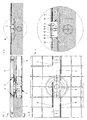
- Fig. 1 a
- einen Längsschnitt durch eine erste Ausführungsform einer erfindungsgemäßen Ablaufvorrichtung;
- Fig. 1 b
- eine Draufsicht auf die Ablaufvorrichtung gemäß Figur 1a;
- Fig. 1 c
- einen Schnitt gemäß den Pfeilen Ic-Ic in Figur 1a;
- Fig. 1d
- eine Detailvergrößerung gemäß Id in Figur 1c;
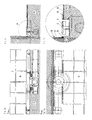
- Fig. 2a
- einen Längsschnitt durch eine zweite Ausführungsform einer erfindungsgemäßen Ablaufvorrichtung;
- Fig. 2b
- eine Draufsicht auf die Ablaufvorrichtung gemäß Figur 2a;
- Fig. 2c
- einen Schnitt gemäß den Pfeilen llc-llc in Figur 2a;
- Fig. 2d
- eine Detailansicht gemäß IId in Figur 2c.
- Aus Figur 1a bis Figur 1d ist ersichtlich, dass die erfindungsgemäße Ablaufvorrichtung eine Ablaufwanne 1 umfasst, die einen im Wesentlichen U-förmigen Querschnitt aufweist. Dabei ist das U der Ablaufwanne 1 nach oben geöffnet, so dass in der Ablaufwanne 1 Wasser beispielsweise zu einer Öffnung 6 fließen kann, durch die hindurch das Wasser in einen unterhalb der Ablaufwanne angeordneten Ablauftopf 7 gelangen kann. Dieser Ablauftopf kann wie in dem abgebildeten Ausführungsbeispiel mit einem Ablaufrohr 5 verbunden sein.
- In die Ablaufwanne 1 kann von oben ein Abdeckelement 2 eingebracht sein, das in dem abgebildeten Ausführungsbeispiel ebenfalls einen U-förmigen Querschnitt aufweist. Das U des Abdeckelementes 2 ist nach unten geöffnet. Das Abdeckelement 2 weist in Querrichtung, das heißt in horizontaler Richtung senkrecht zur Längserstreckung der rinnenähnlichen Abdeckwanne 1, eine geringere Abmessung auf als die Abdeckwanne 1. Auf diese Weise entsteht beidseitig des Abdeckelementes 2 ein länglicher Schlitz 8, durch den hindurch Wasser in die Ablaufwanne 1 eintreten kann.
- Das Abdeckelement 2 ist auf eine Mehrzahl von Haltemitteln 3 aufgebracht. Die Haltemittel 3 umfassen ein stempelförmiges Teil 9, das höhenverstellbar in einer Hülse 10 gehaltert ist. Die Hülse 10 kann beispielsweise auf dem Boden der Ablaufwanne 1 befestigt sein. Die Hülse 10 kann ein Innengewinde aufweisen, in die ein Stift 11 des stempelförmigen Teiles 9 mittels eines Außengewindes einschraubbar ist. Auf diese Weise kann das stempelförmige Teil 9 gegenüber der Hülse 10 höhenverstellbar sein.
- Das stempelförmige Teil 9 kann einen Auflageteller 12 umfassen, der in seinen Querabmessungen in etwa dem inneren Abstand zwischen den beiden U-Schenkeln des Abdeckelementes 2 entspricht, so dass das Abdeckelement 2 vergleichsweise passend auf die Auflageteller 12 der unterschiedlichen Haltemittel 3 aufbringbar ist.
- Insbesondere aus Figur 1d ist ersichtlich, dass die Ablaufwanne 1 sich nach außen in Querrichtung erstreckende kragenförmige Flansche 13 umfasst. Aus Figur 1d ist ebenfalls ersichtlich, dass die Ablaufwanne 1 in eine Öffnung 4 des die Öffnung umgebenden Bodens 14 einbringbar ist. Dabei können die Flansche 13 auf dem die Öffnung 4 umgebenden Teil des Bodens 14 aufliegen. Auf die Oberseite der Flansche 13 können mit geeigneten Klebern oder dergleichen die Fliesen 15 aufgebracht werden. Der ablaufwannenseitige Abschluss der Fliesen 15 kann durch winkelförmige Leisten 16 erzielt werden, die beispielsweise als so genannte Schlüterschienen ausgebildet sein können.
- Durch die Höhenverstellbarkeit der Haltemittel 3 kann das Abdeckelement 2 höhenverstellt werden. Dadurch wird der Einbau der erfindungsgemäßen Ablaufvorrichtung deutlich vereinfacht. Die Ablaufvorrichtung kann in die Bodenöffnung 4 eingebracht werden. Daran anschließend können handelsübliche Fliesen 15 auf die Flansche 13 aufgebracht werden. Diese Fliesen können Dicken zwischen beispielsweise 5 mm und 20 mm aufweisen. Daran anschließend werden die Haltemittel 3 derart in der Höhe verstellt, dass nach Aufbringung des Abdeckelementes 2 die Oberseite des Abdeckelementes 2 mit der Oberseite der Fliesen 15 fluchtet. Falls die Ablaufwanne 1 geneigt in die Öffnung 4 eingebracht wurde, kann eine derartige unerwünschte Neigung durch eine entsprechend unterschiedliche Höhe der Haltemittel 3 ausgeglichen werden.
- Figur 2a bis Figur 2d zeigen die Anbringung der Ablaufvorrichtung im Randbereich zwischen Boden 14 und Wand 17 eines Raumes. In Figur 2a bis Figur 2d sind gleiche Teile mit gleichen Bezugszeichen versehen wie in Figur 1a bis Figur 1d.
- Insbesondere aus Figur 2d ist ersichtlich, dass einer der beiden Flansche 13 sich wie in Figur 1d parallel zum Boden erstreckt, wohingegen der andere der beiden Flansche 13 von der Ablaufwanne im Wesentlichen senkrecht nach oben ragt und sich parallel zur Wand 17 erstreckt. Auch bei einer derartigen Einbausituation kann durch die höhenverstellbaren Haltemittel 3 eine optisch ansprechende Anpassung an die vorhandenen Fliesenspiegel erreicht werden.
- Beispielsweise kann der Anschluss zwischen den Wandfliesen 18 und der Oberseite der Ablaufwanne 1 durch eine Silikonfuge 19 realisiert werden.
- Die Ablaufwanne 1 und das Abdeckelement 2 können aus beliebigen gängigen Materialien wie Metall oder Kunststoff gefertigt sein. Anstelle eines nach unten offenen U-förmigen Abdeckelementes kann auch ein rostähnliches Teil höhenverstellbar in der Ablaufwanne 1 gehaltert sein.
- Die Haltemittel 3 können derart ausgebildet sein, dass die Einbauhöhe der Ablaufwanne 1 und des Abdeckelementes 2 sehr gering ist, beispielsweise nur etwa 20 mm beträgt.
- Der Schlitz 8 kann sich nicht nur in Längsrichtung zwischen Ablaufwanne 1 und Abdeckelement 2 erstrecken, sondern sich umlaufend um das Abdeckelement 2 herum erstrecken. Der Schlitz 8 kann einen optimalen Wasserdurchfluss in die Ablaufwanne 1 gewährleisten.
Claims (11)
- Ablaufvorrichtung für den Einbau in eine Bodenöffnung (4) eines Badezimmers oder dergleichen, umfassend
eine längliche, in die Bodenöffnung (4) einbringbare Ablaufwanne (1), die strömungstechnisch mit einem Ablaufrohr (5) verbunden oder verbindbar ist;
mindestens ein Abdeckelement (2), das im Gebrauchszustand die Ablaufwanne (1) nach oben zumindest teilweise abdeckt, wobei zwischen dem Abdeckelement (2) und Teilen der Ablaufwanne (1) ein Schlitz (8) gebildet ist, durch den Wasser in die Ablaufwanne (1) hineinlaufen kann;
dadurch gekennzeichnet, dass
die Ablaufvorrichtung Haltemittel (3) umfasst, die eine höhenverstellbare Halterung des mindestens einen Abdeckelements (2) ermöglichen. - Ablaufvorrichtung nach Anspruch 1, dadurch gekennzeichnet, dass die Haltemittel (3) in der Ablaufwanne (1) angeordnet sind.
- Ablaufvorrichtung nach einem der Ansprüche 1 oder 2, dadurch gekennzeichnet, dass die Haltemittel (3) mindestens einen Auflageteller (12) umfassen, auf den das mindestens eine Abdeckelement (2) aufgebracht werden kann.
- Ablaufvorrichtung nach einem der Ansprüche 1 bis 3, dadurch gekennzeichnet, dass die Haltemittel (3) höhenverstellbar sind, wobei vorzugsweise die Höhenverstellung über ineinander greifende Gewindeteile realisiert wird.
- Ablaufvorrichtung nach einem der Ansprüche 1 bis 4, dadurch gekennzeichnet, dass das Abdeckelement (2) einen nach unten offenen U-förmigen Querschnitt aufweist.
- Ablaufvorrichtung nach einem der Ansprüche 3 bis 5, dadurch gekennzeichnet, dass die Auflageteller (12) passend in das Abdeckelement (2) von unten einbringbar sind.
- Ablaufvorrichtung nach einem der Ansprüche 5 oder 6, dadurch gekennzeichnet, dass die Ausdehnung des Auflagetellers (12) in Querrichtung der Ablaufwanne (1) dem Abstand zwischen den U-Schenkeln des Abdeckelements (2) entspricht.
- Ablaufvorrichtung nach einem der Ansprüche 1 bis 7, dadurch gekennzeichnet, dass der Schlitz (8) das Abdeckelement (2) umlaufend umgibt.
- Ablaufvorrichtung nach einem der Ansprüche 1 bis 8, dadurch gekennzeichnet, dass die Ablaufvorrichtung mindestens einen Flansch (13) für die Auflage oder Anlage von Fliesen aufweist, der sich von der Ablaufwanne (1) weg erstreckt.
- Ablaufvorrichtung nach Anspruch 9, dadurch gekennzeichnet, dass der mindestens eine Flansch (13) oder mindestens einer der Flansche (13) sich im eingebauten Zustand der Ablaufvorrichtung im wesentlichen vertikal nach oben erstreckt und zur Anlage von Wandfliesen (18) dienen kann.
- Anordnung einer Ablaufvorrichtung in einer Öffnung eines Bodens (14), der zumindest benachbart zu der Ablaufvorrichtung mit Fliesen (15) bedeckt ist, gekennzeichnet durch eine Ablaufvorrichtung nach einem der Ansprüche 1 bis 10.
Priority Applications (1)
| Application Number | Priority Date | Filing Date | Title |
|---|---|---|---|
| PL05022129T PL1647642T3 (pl) | 2004-10-13 | 2005-10-11 | Urządzenia odpływowe |
Applications Claiming Priority (1)
| Application Number | Priority Date | Filing Date | Title |
|---|---|---|---|
| DE102004049944.6A DE102004049944B4 (de) | 2004-10-13 | 2004-10-13 | Ablaufvorrichtung für den Einbau in eine Bodenöffnung |
Publications (3)
| Publication Number | Publication Date |
|---|---|
| EP1647642A2 true EP1647642A2 (de) | 2006-04-19 |
| EP1647642A3 EP1647642A3 (de) | 2006-09-20 |
| EP1647642B1 EP1647642B1 (de) | 2009-12-30 |
Family
ID=35548563
Family Applications (1)
| Application Number | Title | Priority Date | Filing Date |
|---|---|---|---|
| EP05022129A Expired - Lifetime EP1647642B1 (de) | 2004-10-13 | 2005-10-11 | Ablaufvorrichtung |
Country Status (7)
| Country | Link |
|---|---|
| EP (1) | EP1647642B1 (de) |
| AT (1) | ATE453766T1 (de) |
| DE (2) | DE102004049944B4 (de) |
| DK (1) | DK1647642T3 (de) |
| ES (1) | ES2339254T3 (de) |
| PL (1) | PL1647642T3 (de) |
| PT (1) | PT1647642E (de) |
Cited By (8)
| Publication number | Priority date | Publication date | Assignee | Title |
|---|---|---|---|---|
| EP1905907A1 (de) * | 2006-09-22 | 2008-04-02 | Dallmer GmbH & Co. KG | Ablaufvorrichtung für die zumindest teilweise Einbringung in einen Boden eines Raumes |
| EP2037052A1 (de) * | 2007-09-12 | 2009-03-18 | Dallmer GmbH & Co. KG | Bodenablauf mit akustisch entkoppeltem Wandanschluss |
| NL1034911C2 (nl) * | 2008-01-14 | 2009-07-15 | Easy Sanitairy Solutions Bv | Afvoer met stelframe. |
| DE102008050094A1 (de) | 2008-10-06 | 2010-04-08 | Dallmer Gmbh & Co. Kg | Ablaufvorrichtung |
| EP2184414A1 (de) * | 2008-11-10 | 2010-05-12 | Schaco Handel AG | Komponenten für eine bodengleiche Ablaufvorrichtung und entsprechend aufgebaute Dusche |
| EP2581507A1 (de) | 2011-10-12 | 2013-04-17 | Thumag AG | Dusche und Profilelement hierfür |
| DE102013102122A1 (de) | 2013-03-04 | 2014-09-04 | Dallmer Gmbh & Co. Kg | Ablaufvorrichtung |
| EP2354341A3 (de) * | 2010-02-05 | 2015-03-18 | Urs Gassmann | Ablaufrinne mit höhenverstellbarer Abdeckung |
Families Citing this family (4)
| Publication number | Priority date | Publication date | Assignee | Title |
|---|---|---|---|---|
| DE102011051496B4 (de) | 2011-07-01 | 2013-04-04 | Stephan Wedi | Überbausystem für einen im Bodenbereich befindlichen Ablauf |
| DE102013105544A1 (de) | 2013-05-29 | 2014-12-04 | Wedi Gmbh | Wasserablaufvorrichtung für eine sanitäre Anlage, wie einen bodenebenen Duschplatz |
| EP3056618B1 (de) | 2015-02-10 | 2018-05-30 | SANIPAT GmbH | Höhenjustierbarer Rinnensockel für die Abdeckung einer Ablaufrinne |
| DE102019100427A1 (de) * | 2019-01-09 | 2020-07-09 | Dallmer Gmbh & Co. Kg | Ablaufvorrichtung für den zumindest teilweisen Einbau in den Boden eines Raumes |
Family Cites Families (10)
| Publication number | Priority date | Publication date | Assignee | Title |
|---|---|---|---|---|
| DE3214442C2 (de) * | 1982-04-20 | 1987-01-29 | Hauraton Gmbh Betonwarenfabrik, 7550 Rastatt | Entwässerungsrinne für Flachdächer |
| DK18890D0 (da) * | 1990-01-24 | 1990-01-24 | Joergen Mosbaek Johannessen | Gulvafloeb og afloebsrender med sugevirkning |
| ATE160841T1 (de) * | 1993-01-14 | 1997-12-15 | Schoop & Co Ag | Entwässerungsrinne für flachdächer und terrassen |
| ATE168154T1 (de) * | 1994-06-16 | 1998-07-15 | Ahlmann Aco Severin | Hochbauentwässerungsrinne |
| CA2193760C (en) * | 1995-12-29 | 2001-12-04 | Allen R. Becker | Trench drain |
| DE29817430U1 (de) * | 1997-09-29 | 2000-02-17 | SITA-Bauelemente GmbH, 33442 Herzebrock-Clarholz | Abdeckung für Entwässerungsrinnen |
| US5911518A (en) * | 1998-05-04 | 1999-06-15 | Eagle Natural Stone | Shower bath and drain |
| ES2250365T5 (es) * | 2000-03-24 | 2012-03-30 | Unidrain A/S | Drenaje y estructura de edificio que tiene un drenaje |
| DE20017032U1 (de) * | 2000-10-04 | 2002-02-28 | Gutjahr, Walter, 64404 Bickenbach | Verstellbare Drainagerost-Halterung |
| GB0209754D0 (en) * | 2002-04-29 | 2002-06-05 | Alumasc Construction Products | Drain cover unit |
-
2004
- 2004-10-13 DE DE102004049944.6A patent/DE102004049944B4/de not_active Expired - Lifetime
-
2005
- 2005-10-11 DK DK05022129.0T patent/DK1647642T3/da active
- 2005-10-11 AT AT05022129T patent/ATE453766T1/de active
- 2005-10-11 PT PT05022129T patent/PT1647642E/pt unknown
- 2005-10-11 EP EP05022129A patent/EP1647642B1/de not_active Expired - Lifetime
- 2005-10-11 PL PL05022129T patent/PL1647642T3/pl unknown
- 2005-10-11 DE DE502005008770T patent/DE502005008770D1/de not_active Expired - Lifetime
- 2005-10-11 ES ES05022129T patent/ES2339254T3/es not_active Expired - Lifetime
Cited By (11)
| Publication number | Priority date | Publication date | Assignee | Title |
|---|---|---|---|---|
| EP1905907A1 (de) * | 2006-09-22 | 2008-04-02 | Dallmer GmbH & Co. KG | Ablaufvorrichtung für die zumindest teilweise Einbringung in einen Boden eines Raumes |
| EP2037052A1 (de) * | 2007-09-12 | 2009-03-18 | Dallmer GmbH & Co. KG | Bodenablauf mit akustisch entkoppeltem Wandanschluss |
| NL1034911C2 (nl) * | 2008-01-14 | 2009-07-15 | Easy Sanitairy Solutions Bv | Afvoer met stelframe. |
| WO2009091245A1 (en) * | 2008-01-14 | 2009-07-23 | Easy Sanitairy Solutions B.V. | Drain with adjusting frame |
| AU2009205825B2 (en) * | 2008-01-14 | 2012-11-08 | Easy Sanitairy Solutions B.V. | Drain with adjusting frame |
| US8967190B2 (en) | 2008-01-14 | 2015-03-03 | Easy Sanitary Solutions B.V. | Drain with adjusting frame |
| DE102008050094A1 (de) | 2008-10-06 | 2010-04-08 | Dallmer Gmbh & Co. Kg | Ablaufvorrichtung |
| EP2184414A1 (de) * | 2008-11-10 | 2010-05-12 | Schaco Handel AG | Komponenten für eine bodengleiche Ablaufvorrichtung und entsprechend aufgebaute Dusche |
| EP2354341A3 (de) * | 2010-02-05 | 2015-03-18 | Urs Gassmann | Ablaufrinne mit höhenverstellbarer Abdeckung |
| EP2581507A1 (de) | 2011-10-12 | 2013-04-17 | Thumag AG | Dusche und Profilelement hierfür |
| DE102013102122A1 (de) | 2013-03-04 | 2014-09-04 | Dallmer Gmbh & Co. Kg | Ablaufvorrichtung |
Also Published As
| Publication number | Publication date |
|---|---|
| EP1647642A3 (de) | 2006-09-20 |
| EP1647642B1 (de) | 2009-12-30 |
| DE102004049944A1 (de) | 2006-04-20 |
| PT1647642E (pt) | 2010-04-01 |
| DE102004049944B4 (de) | 2015-04-02 |
| ATE453766T1 (de) | 2010-01-15 |
| DE502005008770D1 (de) | 2010-02-11 |
| ES2339254T3 (es) | 2010-05-18 |
| PL1647642T3 (pl) | 2010-07-30 |
| DK1647642T3 (da) | 2010-05-10 |
Similar Documents
| Publication | Publication Date | Title |
|---|---|---|
| EP2539517B1 (de) | Bodenablauf mit höhenverstellbarem rahmen für einen gitterrost | |
| EP2315544B1 (de) | Schaumstoff-duschbodenelement | |
| EP1647642A2 (de) | Ablaufvorrichtung | |
| DE202010007534U1 (de) | Entwässerungsablauf zum Einbau in eine Bodenöffnung eines Duschplatzes | |
| DE202008002346U1 (de) | Vorrichtung zur Montage von Solarmodulen | |
| DE202019107083U1 (de) | Rahmen für einen Bodenablauf | |
| DE102007060444B4 (de) | Bodenablauf | |
| DE102004025874A1 (de) | Ablaufrinne | |
| EP4283059A1 (de) | Verlegekasten zur aufnahme einer ablaufgarnitur | |
| DE102005036576B4 (de) | Ablaufvorrichtung für die Anordnung an einer Bodenplatte mit einer Öffung für Abwasser | |
| EP1916347A2 (de) | Einlaufeinrichtung für einen Bodenablauf und Bodenablauf | |
| DE202021105102U1 (de) | Waschbecken für Räume mit erhöhten Hygieneanforderungen, Zusammenstellung für die Montage des Waschbeckens und Waschtisch | |
| EP3942980B1 (de) | Wanneninstallation | |
| DE20208782U1 (de) | Bauzaun sowie Aushebesicherungsvorrichtung für einen Bauzaun | |
| DE102012106924A1 (de) | Ablaufanordnung | |
| DE102013101207A1 (de) | Ablaufvorrichtung | |
| EP1674628B1 (de) | Ablaufvorrichtung. | |
| DE202009017155U1 (de) | Bodenablauf für eine sanitäre Installation | |
| DE102006051130B4 (de) | Ablaufvorrichtung für die zumindest teilweise Einbringung in einen Boden eines Raumes | |
| EP1561868B1 (de) | Ablaufvorrichtung für eine Duschwanne | |
| EP2119837B1 (de) | Ablaufgarnitur für Wasch- oder Spülbecken | |
| DE102004011853A1 (de) | Ablaufvorrichtung für eine Dusche oder dergleichen | |
| DE102022131506A1 (de) | Mobiles Hochwasserschutzsystem | |
| DE10210496C1 (de) | Vorrichtung zur Positionierung eines Siphons | |
| DE202009003121U1 (de) | Befliesbare Stützvorrichtung |
Legal Events
| Date | Code | Title | Description |
|---|---|---|---|
| PUAI | Public reference made under article 153(3) epc to a published international application that has entered the european phase |
Free format text: ORIGINAL CODE: 0009012 |
|
| AK | Designated contracting states |
Kind code of ref document: A2 Designated state(s): AT BE BG CH CY CZ DE DK EE ES FI FR GB GR HU IE IS IT LI LT LU LV MC NL PL PT RO SE SI SK TR |
|
| AX | Request for extension of the european patent |
Extension state: AL BA HR MK YU |
|
| PUAL | Search report despatched |
Free format text: ORIGINAL CODE: 0009013 |
|
| AK | Designated contracting states |
Kind code of ref document: A3 Designated state(s): AT BE BG CH CY CZ DE DK EE ES FI FR GB GR HU IE IS IT LI LT LU LV MC NL PL PT RO SE SI SK TR |
|
| AX | Request for extension of the european patent |
Extension state: AL BA HR MK YU |
|
| 17P | Request for examination filed |
Effective date: 20070320 |
|
| 17Q | First examination report despatched |
Effective date: 20070420 |
|
| AKX | Designation fees paid |
Designated state(s): AT BE BG CH CY CZ DE DK EE ES FI FR GB GR HU IE IS IT LI LT LU LV MC NL PL PT RO SE SI SK TR |
|
| GRAC | Information related to communication of intention to grant a patent modified |
Free format text: ORIGINAL CODE: EPIDOSCIGR1 |
|
| GRAP | Despatch of communication of intention to grant a patent |
Free format text: ORIGINAL CODE: EPIDOSNIGR1 |
|
| GRAS | Grant fee paid |
Free format text: ORIGINAL CODE: EPIDOSNIGR3 |
|
| GRAA | (expected) grant |
Free format text: ORIGINAL CODE: 0009210 |
|
| AK | Designated contracting states |
Kind code of ref document: B1 Designated state(s): AT BE BG CH CY CZ DE DK EE ES FI FR GB GR HU IE IS IT LI LT LU LV MC NL PL PT RO SE SI SK TR |
|
| REG | Reference to a national code |
Ref country code: GB Ref legal event code: FG4D Free format text: NOT ENGLISH |
|
| REG | Reference to a national code |
Ref country code: CH Ref legal event code: EP |
|
| REG | Reference to a national code |
Ref country code: IE Ref legal event code: FG4D |
|
| REF | Corresponds to: |
Ref document number: 502005008770 Country of ref document: DE Date of ref document: 20100211 Kind code of ref document: P |
|
| REG | Reference to a national code |
Ref country code: PT Ref legal event code: SC4A Free format text: AVAILABILITY OF NATIONAL TRANSLATION Effective date: 20100326 |
|
| REG | Reference to a national code |
Ref country code: NL Ref legal event code: T3 |
|
| REG | Reference to a national code |
Ref country code: SE Ref legal event code: TRGR |
|
| REG | Reference to a national code |
Ref country code: GR Ref legal event code: EP Ref document number: 20100400736 Country of ref document: GR |
|
| PG25 | Lapsed in a contracting state [announced via postgrant information from national office to epo] |
Ref country code: LT Free format text: LAPSE BECAUSE OF FAILURE TO SUBMIT A TRANSLATION OF THE DESCRIPTION OR TO PAY THE FEE WITHIN THE PRESCRIBED TIME-LIMIT Effective date: 20091230 |
|
| REG | Reference to a national code |
Ref country code: DK Ref legal event code: T3 |
|
| REG | Reference to a national code |
Ref country code: ES Ref legal event code: FG2A Ref document number: 2339254 Country of ref document: ES Kind code of ref document: T3 |
|
| LTIE | Lt: invalidation of european patent or patent extension |
Effective date: 20091230 |
|
| PG25 | Lapsed in a contracting state [announced via postgrant information from national office to epo] |
Ref country code: SI Free format text: LAPSE BECAUSE OF FAILURE TO SUBMIT A TRANSLATION OF THE DESCRIPTION OR TO PAY THE FEE WITHIN THE PRESCRIBED TIME-LIMIT Effective date: 20091230 Ref country code: LV Free format text: LAPSE BECAUSE OF FAILURE TO SUBMIT A TRANSLATION OF THE DESCRIPTION OR TO PAY THE FEE WITHIN THE PRESCRIBED TIME-LIMIT Effective date: 20091230 |
|
| PG25 | Lapsed in a contracting state [announced via postgrant information from national office to epo] |
Ref country code: BG Free format text: LAPSE BECAUSE OF FAILURE TO SUBMIT A TRANSLATION OF THE DESCRIPTION OR TO PAY THE FEE WITHIN THE PRESCRIBED TIME-LIMIT Effective date: 20100330 Ref country code: EE Free format text: LAPSE BECAUSE OF FAILURE TO SUBMIT A TRANSLATION OF THE DESCRIPTION OR TO PAY THE FEE WITHIN THE PRESCRIBED TIME-LIMIT Effective date: 20091230 Ref country code: IS Free format text: LAPSE BECAUSE OF FAILURE TO SUBMIT A TRANSLATION OF THE DESCRIPTION OR TO PAY THE FEE WITHIN THE PRESCRIBED TIME-LIMIT Effective date: 20100430 Ref country code: RO Free format text: LAPSE BECAUSE OF FAILURE TO SUBMIT A TRANSLATION OF THE DESCRIPTION OR TO PAY THE FEE WITHIN THE PRESCRIBED TIME-LIMIT Effective date: 20091230 |
|
| REG | Reference to a national code |
Ref country code: PL Ref legal event code: T3 |
|
| REG | Reference to a national code |
Ref country code: HU Ref legal event code: AG4A Ref document number: E007704 Country of ref document: HU |
|
| PG25 | Lapsed in a contracting state [announced via postgrant information from national office to epo] |
Ref country code: SK Free format text: LAPSE BECAUSE OF FAILURE TO SUBMIT A TRANSLATION OF THE DESCRIPTION OR TO PAY THE FEE WITHIN THE PRESCRIBED TIME-LIMIT Effective date: 20091230 |
|
| PG25 | Lapsed in a contracting state [announced via postgrant information from national office to epo] |
Ref country code: CY Free format text: LAPSE BECAUSE OF FAILURE TO SUBMIT A TRANSLATION OF THE DESCRIPTION OR TO PAY THE FEE WITHIN THE PRESCRIBED TIME-LIMIT Effective date: 20091230 |
|
| PLBE | No opposition filed within time limit |
Free format text: ORIGINAL CODE: 0009261 |
|
| STAA | Information on the status of an ep patent application or granted ep patent |
Free format text: STATUS: NO OPPOSITION FILED WITHIN TIME LIMIT |
|
| 26N | No opposition filed |
Effective date: 20101001 |
|
| PG25 | Lapsed in a contracting state [announced via postgrant information from national office to epo] |
Ref country code: MC Free format text: LAPSE BECAUSE OF NON-PAYMENT OF DUE FEES Effective date: 20101031 |
|
| REG | Reference to a national code |
Ref country code: DE Ref legal event code: R008 Ref document number: 502005008770 Country of ref document: DE |
|
| REG | Reference to a national code |
Ref country code: DE Ref legal event code: R097 Ref document number: 502005008770 Country of ref document: DE |
|
| REG | Reference to a national code |
Ref country code: DE Ref legal event code: R039 Ref document number: 502005008770 Country of ref document: DE Effective date: 20120228 |
|
| REG | Reference to a national code |
Ref country code: DE Ref legal event code: R040 Ref document number: 502005008770 Country of ref document: DE Effective date: 20120312 |
|
| PG25 | Lapsed in a contracting state [announced via postgrant information from national office to epo] |
Ref country code: LU Free format text: LAPSE BECAUSE OF NON-PAYMENT OF DUE FEES Effective date: 20101011 |
|
| PGFP | Annual fee paid to national office [announced via postgrant information from national office to epo] |
Ref country code: DK Payment date: 20141022 Year of fee payment: 10 |
|
| PGFP | Annual fee paid to national office [announced via postgrant information from national office to epo] |
Ref country code: SE Payment date: 20141021 Year of fee payment: 10 Ref country code: IE Payment date: 20141024 Year of fee payment: 10 Ref country code: FI Payment date: 20141013 Year of fee payment: 10 Ref country code: GR Payment date: 20141014 Year of fee payment: 10 |
|
| PGFP | Annual fee paid to national office [announced via postgrant information from national office to epo] |
Ref country code: PT Payment date: 20141010 Year of fee payment: 10 |
|
| PGFP | Annual fee paid to national office [announced via postgrant information from national office to epo] |
Ref country code: IT Payment date: 20141029 Year of fee payment: 10 |
|
| REG | Reference to a national code |
Ref country code: FR Ref legal event code: PLFP Year of fee payment: 11 |
|
| REG | Reference to a national code |
Ref country code: PT Ref legal event code: MM4A Free format text: LAPSE DUE TO NON-PAYMENT OF FEES Effective date: 20160411 |
|
| REG | Reference to a national code |
Ref country code: DK Ref legal event code: EBP Effective date: 20151031 |
|
| REG | Reference to a national code |
Ref country code: SE Ref legal event code: EUG |
|
| REG | Reference to a national code |
Ref country code: GR Ref legal event code: ML Ref document number: 20100400736 Country of ref document: GR Effective date: 20160506 |
|
| REG | Reference to a national code |
Ref country code: IE Ref legal event code: MM4A |
|
| PG25 | Lapsed in a contracting state [announced via postgrant information from national office to epo] |
Ref country code: IT Free format text: LAPSE BECAUSE OF NON-PAYMENT OF DUE FEES Effective date: 20151011 Ref country code: GR Free format text: LAPSE BECAUSE OF NON-PAYMENT OF DUE FEES Effective date: 20160506 |
|
| PG25 | Lapsed in a contracting state [announced via postgrant information from national office to epo] |
Ref country code: PT Free format text: LAPSE BECAUSE OF NON-PAYMENT OF DUE FEES Effective date: 20160411 Ref country code: SE Free format text: LAPSE BECAUSE OF NON-PAYMENT OF DUE FEES Effective date: 20151012 |
|
| REG | Reference to a national code |
Ref country code: FR Ref legal event code: PLFP Year of fee payment: 12 |
|
| PG25 | Lapsed in a contracting state [announced via postgrant information from national office to epo] |
Ref country code: IE Free format text: LAPSE BECAUSE OF NON-PAYMENT OF DUE FEES Effective date: 20151011 Ref country code: DK Free format text: LAPSE BECAUSE OF NON-PAYMENT OF DUE FEES Effective date: 20151031 |
|
| PG25 | Lapsed in a contracting state [announced via postgrant information from national office to epo] |
Ref country code: FI Free format text: LAPSE BECAUSE OF NON-PAYMENT OF DUE FEES Effective date: 20151011 |
|
| REG | Reference to a national code |
Ref country code: FR Ref legal event code: PLFP Year of fee payment: 13 |
|
| REG | Reference to a national code |
Ref country code: FR Ref legal event code: PLFP Year of fee payment: 14 |
|
| PGFP | Annual fee paid to national office [announced via postgrant information from national office to epo] |
Ref country code: GB Payment date: 20201022 Year of fee payment: 16 |
|
| PGFP | Annual fee paid to national office [announced via postgrant information from national office to epo] |
Ref country code: ES Payment date: 20211223 Year of fee payment: 17 Ref country code: TR Payment date: 20211007 Year of fee payment: 17 Ref country code: CZ Payment date: 20211001 Year of fee payment: 17 |
|
| PGFP | Annual fee paid to national office [announced via postgrant information from national office to epo] |
Ref country code: HU Payment date: 20211020 Year of fee payment: 17 Ref country code: FR Payment date: 20211021 Year of fee payment: 17 Ref country code: BE Payment date: 20211020 Year of fee payment: 17 |
|
| PGFP | Annual fee paid to national office [announced via postgrant information from national office to epo] |
Ref country code: PL Payment date: 20211001 Year of fee payment: 17 |
|
| GBPC | Gb: european patent ceased through non-payment of renewal fee |
Effective date: 20211011 |
|
| PG25 | Lapsed in a contracting state [announced via postgrant information from national office to epo] |
Ref country code: GB Free format text: LAPSE BECAUSE OF NON-PAYMENT OF DUE FEES Effective date: 20211011 |
|
| PG25 | Lapsed in a contracting state [announced via postgrant information from national office to epo] |
Ref country code: CZ Free format text: LAPSE BECAUSE OF NON-PAYMENT OF DUE FEES Effective date: 20221011 |
|
| REG | Reference to a national code |
Ref country code: BE Ref legal event code: MM Effective date: 20221031 |
|
| P01 | Opt-out of the competence of the unified patent court (upc) registered |
Effective date: 20230616 |
|
| PG25 | Lapsed in a contracting state [announced via postgrant information from national office to epo] |
Ref country code: HU Free format text: LAPSE BECAUSE OF NON-PAYMENT OF DUE FEES Effective date: 20221012 Ref country code: FR Free format text: LAPSE BECAUSE OF NON-PAYMENT OF DUE FEES Effective date: 20221031 |
|
| PG25 | Lapsed in a contracting state [announced via postgrant information from national office to epo] |
Ref country code: BE Free format text: LAPSE BECAUSE OF NON-PAYMENT OF DUE FEES Effective date: 20221031 |
|
| REG | Reference to a national code |
Ref country code: ES Ref legal event code: FD2A Effective date: 20231128 |
|
| PG25 | Lapsed in a contracting state [announced via postgrant information from national office to epo] |
Ref country code: PL Free format text: LAPSE BECAUSE OF NON-PAYMENT OF DUE FEES Effective date: 20221011 |
|
| PG25 | Lapsed in a contracting state [announced via postgrant information from national office to epo] |
Ref country code: ES Free format text: LAPSE BECAUSE OF NON-PAYMENT OF DUE FEES Effective date: 20221012 |
|
| PG25 | Lapsed in a contracting state [announced via postgrant information from national office to epo] |
Ref country code: ES Free format text: LAPSE BECAUSE OF NON-PAYMENT OF DUE FEES Effective date: 20221012 |
|
| PG25 | Lapsed in a contracting state [announced via postgrant information from national office to epo] |
Ref country code: TR Free format text: LAPSE BECAUSE OF NON-PAYMENT OF DUE FEES Effective date: 20221011 |
|
| PGFP | Annual fee paid to national office [announced via postgrant information from national office to epo] |
Ref country code: NL Payment date: 20241021 Year of fee payment: 20 |
|
| PGFP | Annual fee paid to national office [announced via postgrant information from national office to epo] |
Ref country code: DE Payment date: 20241031 Year of fee payment: 20 |
|
| PGFP | Annual fee paid to national office [announced via postgrant information from national office to epo] |
Ref country code: AT Payment date: 20241022 Year of fee payment: 20 |
|
| PGFP | Annual fee paid to national office [announced via postgrant information from national office to epo] |
Ref country code: CH Payment date: 20241101 Year of fee payment: 20 |
|
| REG | Reference to a national code |
Ref country code: DE Ref legal event code: R071 Ref document number: 502005008770 Country of ref document: DE Ref country code: CH Ref legal event code: H14 Free format text: ST27 STATUS EVENT CODE: U-0-0-H10-H14 (AS PROVIDED BY THE NATIONAL OFFICE) Effective date: 20251011 |
|
| REG | Reference to a national code |
Ref country code: NL Ref legal event code: MK Effective date: 20251010 |
|
| REG | Reference to a national code |
Ref country code: AT Ref legal event code: MK07 Ref document number: 453766 Country of ref document: AT Kind code of ref document: T Effective date: 20251011 |