EP1647732A2 - Embrayage avec système de fluide sous pression - Google Patents
Embrayage avec système de fluide sous pression Download PDFInfo
- Publication number
- EP1647732A2 EP1647732A2 EP05022064A EP05022064A EP1647732A2 EP 1647732 A2 EP1647732 A2 EP 1647732A2 EP 05022064 A EP05022064 A EP 05022064A EP 05022064 A EP05022064 A EP 05022064A EP 1647732 A2 EP1647732 A2 EP 1647732A2
- Authority
- EP
- European Patent Office
- Prior art keywords
- housing
- coupling device
- cylindrical surface
- clutch
- seal
- Prior art date
- Legal status (The legal status is an assumption and is not a legal conclusion. Google has not performed a legal analysis and makes no representation as to the accuracy of the status listed.)
- Granted
Links
Images


Classifications
-
- F—MECHANICAL ENGINEERING; LIGHTING; HEATING; WEAPONS; BLASTING
- F16—ENGINEERING ELEMENTS AND UNITS; GENERAL MEASURES FOR PRODUCING AND MAINTAINING EFFECTIVE FUNCTIONING OF MACHINES OR INSTALLATIONS; THERMAL INSULATION IN GENERAL
- F16H—GEARING
- F16H48/00—Differential gearings
- F16H48/20—Arrangements for suppressing or influencing the differential action, e.g. locking devices
- F16H48/22—Arrangements for suppressing or influencing the differential action, e.g. locking devices using friction clutches or brakes
-
- B—PERFORMING OPERATIONS; TRANSPORTING
- B60—VEHICLES IN GENERAL
- B60K—ARRANGEMENT OR MOUNTING OF PROPULSION UNITS OR OF TRANSMISSIONS IN VEHICLES; ARRANGEMENT OR MOUNTING OF PLURAL DIVERSE PRIME-MOVERS IN VEHICLES; AUXILIARY DRIVES FOR VEHICLES; INSTRUMENTATION OR DASHBOARDS FOR VEHICLES; ARRANGEMENTS IN CONNECTION WITH COOLING, AIR INTAKE, GAS EXHAUST OR FUEL SUPPLY OF PROPULSION UNITS IN VEHICLES
- B60K17/00—Arrangement or mounting of transmissions in vehicles
- B60K17/34—Arrangement or mounting of transmissions in vehicles for driving both front and rear wheels, e.g. four wheel drive vehicles
- B60K17/348—Arrangement or mounting of transmissions in vehicles for driving both front and rear wheels, e.g. four wheel drive vehicles having differential means for driving one set of wheels, e.g. the front, at one speed and the other set, e.g. the rear, at a different speed
- B60K17/35—Arrangement or mounting of transmissions in vehicles for driving both front and rear wheels, e.g. four wheel drive vehicles having differential means for driving one set of wheels, e.g. the front, at one speed and the other set, e.g. the rear, at a different speed including arrangements for suppressing or influencing the power transfer, e.g. viscous clutches
- B60K17/352—Arrangement or mounting of transmissions in vehicles for driving both front and rear wheels, e.g. four wheel drive vehicles having differential means for driving one set of wheels, e.g. the front, at one speed and the other set, e.g. the rear, at a different speed including arrangements for suppressing or influencing the power transfer, e.g. viscous clutches manually operated
-
- F—MECHANICAL ENGINEERING; LIGHTING; HEATING; WEAPONS; BLASTING
- F16—ENGINEERING ELEMENTS AND UNITS; GENERAL MEASURES FOR PRODUCING AND MAINTAINING EFFECTIVE FUNCTIONING OF MACHINES OR INSTALLATIONS; THERMAL INSULATION IN GENERAL
- F16D—COUPLINGS FOR TRANSMITTING ROTATION; CLUTCHES; BRAKES
- F16D25/00—Fluid-actuated clutches
- F16D25/06—Fluid-actuated clutches in which the fluid actuates a piston incorporated in, i.e. rotating with the clutch
- F16D25/062—Fluid-actuated clutches in which the fluid actuates a piston incorporated in, i.e. rotating with the clutch the clutch having friction surfaces
- F16D25/063—Fluid-actuated clutches in which the fluid actuates a piston incorporated in, i.e. rotating with the clutch the clutch having friction surfaces with clutch members exclusively moving axially
- F16D25/0635—Fluid-actuated clutches in which the fluid actuates a piston incorporated in, i.e. rotating with the clutch the clutch having friction surfaces with clutch members exclusively moving axially with flat friction surfaces, e.g. discs
- F16D25/0638—Fluid-actuated clutches in which the fluid actuates a piston incorporated in, i.e. rotating with the clutch the clutch having friction surfaces with clutch members exclusively moving axially with flat friction surfaces, e.g. discs with more than two discs, e.g. multiple lamellae
-
- F—MECHANICAL ENGINEERING; LIGHTING; HEATING; WEAPONS; BLASTING
- F16—ENGINEERING ELEMENTS AND UNITS; GENERAL MEASURES FOR PRODUCING AND MAINTAINING EFFECTIVE FUNCTIONING OF MACHINES OR INSTALLATIONS; THERMAL INSULATION IN GENERAL
- F16D—COUPLINGS FOR TRANSMITTING ROTATION; CLUTCHES; BRAKES
- F16D25/00—Fluid-actuated clutches
- F16D25/12—Details not specific to one of the before-mentioned types
-
- F—MECHANICAL ENGINEERING; LIGHTING; HEATING; WEAPONS; BLASTING
- F16—ENGINEERING ELEMENTS AND UNITS; GENERAL MEASURES FOR PRODUCING AND MAINTAINING EFFECTIVE FUNCTIONING OF MACHINES OR INSTALLATIONS; THERMAL INSULATION IN GENERAL
- F16H—GEARING
- F16H48/00—Differential gearings
- F16H48/06—Differential gearings with gears having orbital motion
- F16H48/08—Differential gearings with gears having orbital motion comprising bevel gears
-
- F—MECHANICAL ENGINEERING; LIGHTING; HEATING; WEAPONS; BLASTING
- F16—ENGINEERING ELEMENTS AND UNITS; GENERAL MEASURES FOR PRODUCING AND MAINTAINING EFFECTIVE FUNCTIONING OF MACHINES OR INSTALLATIONS; THERMAL INSULATION IN GENERAL
- F16H—GEARING
- F16H48/00—Differential gearings
- F16H48/20—Arrangements for suppressing or influencing the differential action, e.g. locking devices
- F16H48/30—Arrangements for suppressing or influencing the differential action, e.g. locking devices using externally-actuatable means
- F16H48/34—Arrangements for suppressing or influencing the differential action, e.g. locking devices using externally-actuatable means using electromagnetic or electric actuators
-
- F—MECHANICAL ENGINEERING; LIGHTING; HEATING; WEAPONS; BLASTING
- F16—ENGINEERING ELEMENTS AND UNITS; GENERAL MEASURES FOR PRODUCING AND MAINTAINING EFFECTIVE FUNCTIONING OF MACHINES OR INSTALLATIONS; THERMAL INSULATION IN GENERAL
- F16H—GEARING
- F16H48/00—Differential gearings
- F16H48/20—Arrangements for suppressing or influencing the differential action, e.g. locking devices
- F16H2048/204—Control of arrangements for suppressing differential actions
-
- F—MECHANICAL ENGINEERING; LIGHTING; HEATING; WEAPONS; BLASTING
- F16—ENGINEERING ELEMENTS AND UNITS; GENERAL MEASURES FOR PRODUCING AND MAINTAINING EFFECTIVE FUNCTIONING OF MACHINES OR INSTALLATIONS; THERMAL INSULATION IN GENERAL
- F16H—GEARING
- F16H48/00—Differential gearings
- F16H48/20—Arrangements for suppressing or influencing the differential action, e.g. locking devices
- F16H48/30—Arrangements for suppressing or influencing the differential action, e.g. locking devices using externally-actuatable means
- F16H48/34—Arrangements for suppressing or influencing the differential action, e.g. locking devices using externally-actuatable means using electromagnetic or electric actuators
- F16H2048/346—Arrangements for suppressing or influencing the differential action, e.g. locking devices using externally-actuatable means using electromagnetic or electric actuators using a linear motor
-
- F—MECHANICAL ENGINEERING; LIGHTING; HEATING; WEAPONS; BLASTING
- F16—ENGINEERING ELEMENTS AND UNITS; GENERAL MEASURES FOR PRODUCING AND MAINTAINING EFFECTIVE FUNCTIONING OF MACHINES OR INSTALLATIONS; THERMAL INSULATION IN GENERAL
- F16H—GEARING
- F16H48/00—Differential gearings
- F16H48/38—Constructional details
- F16H2048/382—Methods for manufacturing differential gearings
-
- F—MECHANICAL ENGINEERING; LIGHTING; HEATING; WEAPONS; BLASTING
- F16—ENGINEERING ELEMENTS AND UNITS; GENERAL MEASURES FOR PRODUCING AND MAINTAINING EFFECTIVE FUNCTIONING OF MACHINES OR INSTALLATIONS; THERMAL INSULATION IN GENERAL
- F16H—GEARING
- F16H2200/00—Transmissions for multiple ratios
- F16H2200/20—Transmissions using gears with orbital motion
- F16H2200/203—Transmissions using gears with orbital motion characterised by the engaging friction means not of the freewheel type, e.g. friction clutches or brakes
- F16H2200/2071—Transmissions using gears with orbital motion characterised by the engaging friction means not of the freewheel type, e.g. friction clutches or brakes using three freewheel mechanism
-
- F—MECHANICAL ENGINEERING; LIGHTING; HEATING; WEAPONS; BLASTING
- F16—ENGINEERING ELEMENTS AND UNITS; GENERAL MEASURES FOR PRODUCING AND MAINTAINING EFFECTIVE FUNCTIONING OF MACHINES OR INSTALLATIONS; THERMAL INSULATION IN GENERAL
- F16H—GEARING
- F16H48/00—Differential gearings
- F16H48/20—Arrangements for suppressing or influencing the differential action, e.g. locking devices
- F16H48/30—Arrangements for suppressing or influencing the differential action, e.g. locking devices using externally-actuatable means
- F16H48/32—Arrangements for suppressing or influencing the differential action, e.g. locking devices using externally-actuatable means using fluid pressure actuators
Definitions
- the present invention relates to coupling devices of the type used to transmit torque, for example, in a vehicle drive line, and more particularly, to such coupling devices of the type including a fluid pressure operated clutch assembly for controlling the transmission of torque through the coupling device.
- the term “coupling device” will be understood to mean and include a device which is able to transmit torque from an input to one or more outputs, and in which there is a clutch assembly disposed between the input and the output, such that the amount of torque transmitted is a function of the extent of engagement of the clutch assembly.
- the term “coupling device” means and includes both gear-type devices (such as differentials), as well as gearless-type couplings.
- a clutch pack operable to transmit torque between the input (housing connected to the ring gear) and the output (one of the axle shafts), with the degree of engagement of the clutch pack being determined by the fluid pressure in a clutch apply chamber.
- the fluid pressure biases a clutch engagement member (such as a piston) against the clutch pack.
- the differential coupling devices of the cited patents include a gerotor pump having one rotor fixed to rotate with the input, and the other rotor fixed to rotate with the output, such that the flow of pressurized fluid into the clutch apply chamber is generally proportional to the speed difference between the input and the output.
- clutch pack will be understood to mean and include both a multiple friction disc type clutch pack, as well as any of the other well known types of clutch assemblies, such as cone clutches, in which the degree of engagement is generally proportional to the fluid pressure acting on the clutch piston, or on an equivalent clutch-engagement structure.
- the "main" flow path to communicate from a low pressure inlet (receiving fluid from a reservoir) to the inlet to the gerotor pump, and to have a control valve disposed in that flow path, thus controlling clutch apply pressure by limiting fluid flow into the inlet of the pump.
- the fluid pressure in the high pressure portion of the system is typically in the range of about 500 psi to about 1000 psi, while the coupling housing may be rotating, relative to the stationary control valve assembly, at speeds in excess of 1500 rpm, corresponding to a vehicle speed of about 130 mph.
- the housing has conventionally comprised one or more cast iron members, with any surfaces needing a particular flatness, smoothness, etc. being machined, while the rest of the member remains in the "as-cast" condition.
- the plenum and seal arrangement which comprises part of the control valve assembly, is configured generally as in the above-incorporated U.S. Pat. No. 6,464,056, with a pair of high pressure seals received within the plenum and riding on the cylindrical surface of the housing hub portion. It has been observed, during the early stages of the development of the commercial embodiment, that the seal life of the high pressure seals was not nearly acceptable, but the reasons for the insufficient seal life were not at all apparent.
- the resulting pits or porosity on the surface of the hub portion subsequently collect pieces of the glass fibers, which thereafter may act as little "cutting tools" against the inside diameter of the sealing element, as the hub portion rotates within the seal assembly, and/or, it may be that the exposed edges of the pits act to cut the inside diameter of the sealing element. It is the above-described cutting action by either the glass fibers, or the edges of the pits, on the sealing element which is believed to be responsible for the observed, unsatisfactory sealing life, wherein the high pressure which the seals are able to maintain may rapidly decrease over a fairly short period of time.
- a coupling device including a rotatable housing defining a clutch cavity.
- a clutch assembly is disposed in the clutch cavity and includes a first clutch member fixed to rotate with the housing and a second clutch member fixed to rotate with an output.
- the housing defines a pressure chamber and a clutch apply member disposed in the pressure chamber and being operable to bias the first and second clutch members into torque-transmitting relationship in response to the presence of pressurized fluid in the pressure chamber.
- the coupling device includes a source of the pressurized fluid, and a control valve assembly operable to vary the fluid pressure in the pressure chamber in response to variations in an input.
- the housing defines a hub portion defining an outer cylindrical surface, the housing defining a high pressure fluid passage providing fluid communication from the pressure chamber to a first port formed in the outer cylindrical surface.
- the improved coupling device is characterized by a stationary plenum member defining an inner cylindrical surface disposed in a surrounding relationship about the outer cylindrical surface defined by the hub portion.
- the plenum member defines a high pressure fluid passage providing fluid communication from a second port formed in the inner cylindrical surface, in fluid communication with the first port formed in the outer cylindrical surface of the hub portion, to the control valve assembly.
- First and second annular seal members are disposed within the inner cylindrical surface on axially opposite sides of the second port, to define an annular pressure region.
- the hub portion of the housing comprises a member in which at least the outer cylindrical surface is substantially free of graphite porosity.
- FIG. 1 is an axial cross-section of a vehicle differential coupling device of the type with which the present invention may be utilized.
- FIG. 2 is an enlarged, fragmentary, axial cross-section, similar to FIG. 1, illustrating in greater detail that portion of the coupling device with which the improved fluid pressure system of the present invention is most closely associated.
- FIG. 3 is a perspective view of the control valve assembly, including the plenum member, of the coupling device shown in FIGS. 1 and 2, of the type including the subject embodiment of the invention.
- FIG. 4 is a further enlarged, fragmentary, axial cross-section similar to FIG. 2, illustrating in greater detail the seal assembly and hub portion of the present invention, but with the seals removed for ease of illustration.
- FIG. 5 is a further enlarged, somewhat pictorial view of one of the seal members utilized in the subject embodiment of the invention, with the seal member shown within its cavity, but in its "at-rest” condition (i.e., with the hub portion not present).
- FIG. 6 is a further enlarged (relative to FIG. 2) axial cross-section (upper half only) of a plenum and seal assembly, illustrating an alternative embodiment of the present invention.
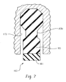
- FIG. 7 is a greatly enlarged, fragmentary, axial cross-section of one seal member made in accordance with the alternative embodiment of FIG. 6, in its "at-rest” condition.
- FIG. 1 illustrates a differential coupling device, generally designated 11, for use in a vehicle drive line, and which is of the general type illustrated and described in the above-incorporated patents, and which is especially well suited to utilize, and benefit from, the improved fluid pressure system of the present invention.
- the differential coupling device 11 comprises a housing, including a gear housing 13, a clutch housing 15, and a valve housing 17, also referred to hereinafter as a "control valve assembly".
- the gear housing 13 and the clutch housing 15 may be held together by any suitable means, well known in the art, such as a plurality of bolts (not shown herein).
- the valve housing 17 is typically retained, axially, by an inner race 18a of a bearing set 18.
- the gear housing 13 defines a gear chamber 19, and disposed therein, but by way of example only, there may be provided a typical differential gear set.
- the input pinion gears 21 may be considered the “input” to the differential coupling device 11, while the side gears 25 and 27 comprises the “outputs” of the coupling device 11 More specifically, for purposes of most of the subsequent description, the side gear 27 will be considered to comprise the "output” of the coupling device 11.
- the ultimate “output” of the coupling device 11 is a pair of axle shafts (not shown herein for simplicity) which would be in splined engagement with the side gears 25 and 27, as will be described further subsequently.
- the side gears 25 and 27 define sets of straight, internal splines 25S and 27S, respectively, which are adapted to receive the right and left axle shafts mentioned previously, whereby the coupling device 11 transmits torque by means of the axle shafts to associated vehicle drive wheels (also not shown), in a manner which is well known, and forms no part of the present invention. It should be clearly understood, however, that the structure described hereinabove is by way of example only, and the present invention may also be used with various other types of coupling device structures. In fact, the fluid pressure system of the present invention may be used generally to control clutch apply pressure in various embodiments of coupling devices and differentials.
- a clutch pack generally designated 29 which, as is shown in greater detail in FIG. 2, comprises a plurality of outer discs 31 which are in splined engagement with a set of internal splines defined by the clutch housing 15.
- the clutch pack 29 includes a plurality of inner discs 33, which are interleaved with the outer discs 31 in a well known manner, the inner discs 33 being in splined engagement with a coupling member 35.
- the coupling member 35 defines a set of internal splines 35S, which are also in splined engagement with the left axle shaft, such that the coupling member 35 is fixed, in the subject embodiment, to rotate with the side gear 27, it being understood that such a spline arrangement, or even the coupling member 35 itself, is not essential to the present invention.
- annular housing insert 37 which cooperates with the adjacent coupling member 35, and with the clutch pack 29, to define a clutch cavity or clutch piston chamber 39.
- a clutch piston 41 Disposed within the clutch piston chamber 39, and moveable axially therein, is a clutch piston 41 which cooperates with the housing insert 37 to define a piston pressure (apply) chamber 43, which may better be seen in FIG. 2.
- piston pressure (apply) chamber 43 As is well known to those skilled in the art of such devices, variations in the fluid pressure in the piston pressure (apply) chamber 43 will result in variations in the axial force applied by the clutch piston 41 to the clutch pack 29 and therefore, will result in variations in the "bias torque", i.e., the torque transmitted through the clutch pack from the input of the coupling 11 to the output.
- gerotor gear set comprising a stationary, eccentric member 45, serving as part of the pump housing, an internally-toothed outer rotor 47, and an externally-toothed inner rotor 49.
- the inner rotor 49 defines a set of straight, internal splines 49S which are also in engagement with the left axle shaft, as described previously, such that the inner rotor 49 is fixed to rotate with the coupling member 35 and the side gear 27.
- the entire differential coupling 11 rotates as a unit, i.e., the housings 13 and 15 and the side gears 25 and 27 and the axle shafts all rotate at the same rotational speed. In that condition, there is no relative rotation between the outer rotor 47 and the inner rotor 49, and therefore, there is no pumping of pressurized fluid from the volume chambers (formed between the teeth of the rotors 47 and 49 when they are relatively rotating).
- the housing insert 37 cooperates with the eccentric member 45 and the clutch housing 15 to define an axial fluid passage 53 which is in open communication with the piston pressure apply chamber 43.
- the clutch housing 15 defines a radial fluid passage 55 which intersects the axial passage 53 and, at its radially inner extent, communicates with another axial fluid passage 57 which then, by means of a short radial fluid passage 59, communicates to an outer cylindrical surface 60 formed by a hub portion 61 of the clutch housing 15.
- the radial passage 59 forms a port in the outer cylindrical surface 60 of the hub portion 61, that port also, hereinafter, bearing the reference numeral "59".
- each of the fluid passages 53, 55, 57, and 59 there are two each of the fluid passages 53, 55, 57, and 59, which would typically be disposed approximately 180 degrees apart, but in the subject embodiment, because of space limitations, are about twenty (20) degrees apart.
- valve housing or control valve assembly 17 which preferably comprises a molded aluminum plenum member, is stationary within the outer differential housing (not shown herein).
- the valve housing 17 receives on its inner periphery, a pair of seal members, generally designated 63, which are disposed on axially opposite sides of the radial passage (port) 59, the seal members 63 being in sealing engagement against the adjacent, outer cylindrical surface 60 of the hub portion 61.
- the valve housing 17 includes an inlet portion 65 which, preferably, extends down into a "source" of low pressure fluid, which would typically comprise a reservoir or sump containing fluid and disposed within the outer differential housing, as is well known in the art.
- the valve housing 17 (which will also be referred to hereinafter as the "plenum member 17") also includes a port portion 67 on which is mounted a pressure control valve assembly, generally designated 69, which is preferably made, and operates, in accordance with the teachings of co-pending application U.S. Serial No. 10/795,651, filed March 8, 2004 in the name of Christopher J. Babin, for a "Coupling Device and Improved Method of Controlling Torque Transmission", assigned to the assignee of the present invention and incorporated herein by reference.
- the control valve assembly 69 is preferably an electrical solenoid-operated valve, changing pressure in the piston pressure apply chamber 43 in response to changes in an electrical input signal.
- the plenum member 17 defines a generally radial passageway 71 (cut through at an angle to the plane of FIG. 2) which extends radially inward to be in continuous fluid communication with the radial passage and port 59.
- the radial passageway 71 has its radially outer end disposed within the port portion 67, and therefore, the radial passageway 71 is disposed adjacent the pressure control valve assembly 69.
- the fluid pressure in the passageway 71 which is effectively the "inlet" of the pressure control valve assembly 69, is substantially identical to the fluid pressure in the piston pressure apply chamber 43, by means of the fluid passages 53, 55, 57, and 59.
- housing members of differentials and couplings devices such as the clutch housing 15, as cast iron members.
- certain surfaces which could not function satisfactorily in the "as-cast” condition, would be machined, or further processed in some other manner.
- the outer cylindrical surface 60 of the hub portion 61 would be one such surface requiring further processing, but as was mentioned previously in the Background of the Disclosure, even with such further machining of the outer cylindrical surface 60, there has still been the observed problem of graphite porosity, and its undesirable interaction with, and effect upon, the seal members 63. Heat treating the cast iron hub portion was found to help somewhat, but the sealing life was still unsatisfactory.
- the clutch housing 15 is formed as a forged steel member. It will be understood by those skilled in the metallurgical arts that the use of a steel member (as opposed to a cast iron member) is preferred (as opposed to other, non-ferrous materials) for the combination of factors such as strength, machinability, and cost offered by steel. Furthermore, the member is described as preferably being a "forged" steel member primarily because of the known cost and strength benefits of a forging, as compared to a machined part.
- the wear sleeve could comprise any of the materials known for use in such applications, such as bronze, but in the subject embodiment, it was determined that bronze would be too soft, that the application is sufficiently severe to require a harder material, and a material such as steel would have to be utilized herein.
- the valve housing 17 comprises a molded aluminum plenum member defining a pair of annular seal cavities 73 and 75, disposed on axially opposite sides of the port 59, and preferably not in direct fluid communication therewith.
- an annular fluid groove 77 Disposed axially between the seal cavities 73 and 75 is an annular fluid groove 77, which is annular to be in continuous fluid communication with the port 59, and is also in fluid communication with the radial passageway 71. Therefore, the fluid groove 77 will also be referred to hereinafter, and especially in the appended claims, as the "second port", communicating with the first port 59.
- the groove 77 is formed in the plenum member 17, rather than in the hub portion 61, because, if the groove 77 were formed in the hub portion 61, then during assembly, as the plenum member 17 is being placed over the hub portion 61, the seal member 63 which is disposed in the seal cavity 75 would have to "pass over" the groove, which could result in damage to the seal member.
- the seal member 63 disposed in the seal cavity 75 merely has to pass over the ports 59, which presents much less potential for damage to the seal member.
- FIG. 5 shows the seal member 63 disposed in the seal cavity 73
- the two seal members 63 and seal cavities 73 and 75 are preferably identical, to simplify machining and seal member inventory.
- the preferred embodiment of the seal member 63 includes a primary sealing element 81 and a secondary sealing element 83, which surrounds the primary sealing element 81.
- the primary sealing element 81 extends radially inward beyond an inner cylindrical surface 85 (see FIG. 4) defined by the plenum member 17.
- the primary sealing element 81 comprises a glass-filled, polytetrafluoroehtylene member (sold under the trademark "Teflon", owned by E. I. Dupont de Nemours and Company) suitable for sealing against a rotating metal surface, under high pressure, and in a high temperature environment.
- Teflon polytetrafluoroehtylene member
- the basic "graphite porosity" problem apparently occurs.
- the secondary sealing element 83 may comprise any of the well known elastomeric type materials, preferably a fluorocarbon, which are conventionally used, or which may be used, for sealing purposes. However, it should be recognized that, in the preferred embodiment, the sealing element 83 does not directly perform a sealing function relative to the surface 60 (although an enlarged circular portion 83C has an interference fit within the rounded portion of the seal cavity 73) and instead, the sealing element 83 is more of a "back-up ring" for the primary sealing element 81.
- the overall height (radial dimension) of the seal member 63 is selected, relative to the height of the seal cavity 73, and relative to the width of the sealing element 83, such that the radial sealing force exerted by the sealing element 81 against the hub portion 61 is within a predetermined range of forces. It is believed to be within the ability of those skilled in the art to make such a selection of the relative heights of the seal member 63 and the seal cavity 73, to get the predetermined, desired sealing force suitable for the range of pressures to which the seal member 63 will be subjected. The desired height to width (H/W) ratio for the seal member will be described in greater detail subsequently.
- the configuration of the seal member 63 (and more specifically, of the secondary sealing element 83) relative to the configuration of the seal cavity 73 has been selected to accomplish several objectives.
- the radially outermost portion 83C of the secondary sealing element 83 is generally rounded and is preferably larger than the adjacent portion of the seal cavity 73, such that, once installed and under fluid pressure, the seal member 63 will not rotate within the plenum member 17, but instead, the only relative rotation involving the seal will be between the seal member 63 and the outer cylindrical surface 60.
- the reason is to minimize seal drag, and the drag between the radially inner surface of the primary sealing element 81 and the surface 60 is much less than would be the drag between the element 83 and the cavity 73, if such rotation were permitted. Also, the material of the sealing element 81 is much better able to withstand such rubbing contact than is the sealing element 83.
- the configuration of the seal member 63 is also selected such that, as the temperature in the region of the seal and hub increases, the secondary sealing element 83 may "expand" within the cavity 73. More specifically, the goal is that the configurations of the seal cavity 73 and the secondary sealing element 83 be selected such that, over the range of operating temperatures, the radial sealing force will remain approximately constant. It is believed to be within the ability of those skilled in the seal art, based upon a reading and understanding of the present specification, to select the configurations of the cavity 73 and the secondary sealing element 83 to achieve such a constant "Force vs. Temperature" relationship.
- the valve housing (plenum member) 17 includes an outer cylindrical portion 91 surrounding an outer diameter formed on, and defined by the clutch housing 15. Disposed between outer diameter of the clutch housing 15 and the outer cylindrical portion 91 is, preferably, a bronze bushing 93, or some other suitable bearing or journal type member. Although this particular arrangement of the bushing 93, or even the basic presence of a bushing, is not essential to the invention, it has been determined through testing that the use of some sort of bearing arrangement between the clutch housing 15 and the plenum member 17 improves the ability to maintain concentricity between the outer cylindrical surface 60 and the inner cylindrical surface 85. Better concentricity between the surfaces 60 and 85 has been found to improve the durability of the sealing arrangement.
- a low pressure seal 95 Disposed immediately adjacent the bronze bushing 93, and just slightly radially inward therefrom, is a low pressure seal 95, shown somewhat schematically in FIG. 2 as comprising an annular square-cut seal member, but from the early stages of development, a lip seal was utilized instead.
- the low pressure seal could comprise any of the conventional low pressure seal materials, such as a urethane, or a butyl rubber, but in the subject embodiment, it was found necessary to utilize materials such as liquid crystal polymers and fluoroelastomers, including Teflon. Neither the configuration nor the material of the low pressure seal 95, or even the presence of a low pressure seal are essential to the practice of the present invention.
- each seal member 63 it is necessary to prepare each seal member 63 by deforming it slightly radially inwardly at one location, so the seal member is no longer "circular", thus reducing temporarily the effective outer diameter of the seal member enough to be able to insert the seal member 63 into its respective seal cavity 73 or 75. Then, when the seal member has been inserted into its seal cavity, the seal member is worked into place within the seal cavity, and again made circular.
- the height-to-width ratio (“H/W” ratio) of the seal member 63 must be selected to provide the desired radial force of the primary sealing element 81 against the surface 60, and during the course of developing the invention, the trend has been toward a greater interference fit between the inside diameter of the sealing element 81 and the outer cylindrical surface 60.
- the H/W ratio must be selected such that it is possible to perform (and perhaps do so manually) the necessary deformation of the seal member, just prior to insertion into the seal cavity.
- the H/W ratio of the seal member 63 is in the range of about 4:1.
- the plenum member 17 may be installed on the clutch housing 15. Noting that the primary sealing element 81 extends radially inward beyond the inner cylindrical surface 85, and thus, temporarily has a smaller inside diameter than the outer diameter of the surface 60, it will be appreciated that sliding the seal members 63 over the hub portion 61 is a delicate operation. Therefore, in accordance with one benefit of the invention, the length of the outer cylindrical portion 91 is selected such that, during assembly, with the plenum member 17 moving from a disassembled position to the right, toward the position shown in FIG.
- the portion 91 begins to slide over the bronze bushing 93 before the seal member 63 in the seal cavity 75 begins to engage the outer cylindrical surface 60.
- the engagement of the outer cylindrical portion 91 "pilots" the plenum member 17 over the hub portion 61, to minimize the lack of concentricity between the outer surface 60 and the inner surface 85.
- the best sealing arrangement is not necessarily accomplished by providing the smoothest possible surface finish for the surface against which the seal member seals.
- the clutch housing 15 was described as preferably being a steel forging.
- the outer cylindrical surface 60 would thereafter be machined, but the particular process used to finish the surface 60 of the hub portion 61 is not an essential feature of the invention. It has been observed that a very good sealing capability may be achieved, in terms of maintaining pressure, and long seal life, when the surface 60 has enough surface roughness that some oil is retained on the surface 60, which can lubricate the sealing element 81, rather than the surface 60 being "wiped dry" by its interaction with the sealing element 81. It has been observed during the development of the invention that, after the coupling device operates awhile, some of the polytetrafluoroehtylene (PTFE) material from the primary sealing element 81 may be transferred to the surface 60.
- PTFE polytetrafluoroehtylene
- FIG. 6 shows a plenum member 117, which is configured slightly differently than the member 17, but such differences are irrelevant to the present invention.
- An outer cylindrical portion 191 of the plenum member 117 has disposed therein a bronze bushing 193, and disposed to the left of the bushing 193 is a low pressure seal assembly 195, including a lip portion 195L which would ride on an adjacent outer surface of the clutch housing 15 to prevent the ingress of air, as mentioned previously.
- the low pressure seal 195 in the alternative embodiment may have a somewhat lower seal drag than would the seal 95 in the first embodiment.
- the seal member 163 comprises a primary sealing element 181 and a secondary sealing element 183, and the sealing elements in this embodiment may comprise the same materials as in the first embodiment.
- the secondary sealing element 183 includes a radially outward, enlarged portion which serves the same purpose as previously described, i.e., to retain the seal member 163 to be non-rotatable within the seal cavity 173.
- One difference in the sealing element 183 is that the portion immediately radially outward of the element 181 is relatively wider than in the case of the element 81, but also, the element 181 is provided with a chamfer or undercut, designated 183U.
- the undercut portion 183U is very effective in achieving the desired springiness of the element 183, to get the desired constant radial force of the primary sealing element 181 against the surface 60.
- the undercut portion 183U also provides a flexibility of the element 181 which is helpful during the assembly process.
- the undercut portion 183U allows enough room for thermal expansion of the secondary sealing element 183, within the seal cavity 173, so that the thermal expansion does not cause excessive radially-inward loading on the primary sealing element 181.
- the H/W ratio of the seal member 63 was stated to be about 4:1.
- the H/W ratio of the seal member 63 i.e., the overall height of the elements 181 and 183 together, in the at-rest condition
- the H/W ratio of the seal member is preferably in the range of about 2.5:1 to about 5:1, but is even more preferably in the range of about 3:1 to about 4:1.
- a seal member within that H/W ratio will, in most applications, provide a good balance between the ability to install the seal member in the seal cavity and the radial sealing force exerted against the adjacent outer surface 60, even over a range of operating temperatures.
- the present invention has been illustrated and described in connection with a high pressure sealing arrangement utilizing two of the "radial" type seal members, 63 and 163.
- it is not essential to the practice of the present invention to have the high pressure region defined by, and between, a pair of the radial type seal members, although it is preferred because the use of the two radial seals as shown herein eliminates any net axial biasing force acting on the plenum member 17, as the pressure of the high pressure fluid varies.
Landscapes
- Engineering & Computer Science (AREA)
- General Engineering & Computer Science (AREA)
- Mechanical Engineering (AREA)
- Physics & Mathematics (AREA)
- Electromagnetism (AREA)
- Chemical & Material Sciences (AREA)
- Analytical Chemistry (AREA)
- Fluid Mechanics (AREA)
- Combustion & Propulsion (AREA)
- Transportation (AREA)
- Hydraulic Clutches, Magnetic Clutches, Fluid Clutches, And Fluid Joints (AREA)
- Sealing Devices (AREA)
- Sealing Of Bearings (AREA)
- Joints Allowing Movement (AREA)
- Supply Devices, Intensifiers, Converters, And Telemotors (AREA)
Applications Claiming Priority (1)
| Application Number | Priority Date | Filing Date | Title |
|---|---|---|---|
| US10/964,134 US7063198B2 (en) | 2004-10-13 | 2004-10-13 | Coupling device and improved fluid pressure system therefor |
Publications (3)
| Publication Number | Publication Date |
|---|---|
| EP1647732A2 true EP1647732A2 (fr) | 2006-04-19 |
| EP1647732A3 EP1647732A3 (fr) | 2006-05-17 |
| EP1647732B1 EP1647732B1 (fr) | 2009-01-07 |
Family
ID=35517439
Family Applications (1)
| Application Number | Title | Priority Date | Filing Date |
|---|---|---|---|
| EP05022064A Expired - Lifetime EP1647732B1 (fr) | 2004-10-13 | 2005-10-10 | Embrayage avec système de fluide sous pression |
Country Status (8)
| Country | Link |
|---|---|
| US (1) | US7063198B2 (fr) |
| EP (1) | EP1647732B1 (fr) |
| JP (1) | JP4915608B2 (fr) |
| KR (1) | KR20060052208A (fr) |
| CN (1) | CN100501183C (fr) |
| AT (1) | ATE420301T1 (fr) |
| DE (1) | DE602005012208D1 (fr) |
| MX (1) | MXPA05010985A (fr) |
Cited By (2)
| Publication number | Priority date | Publication date | Assignee | Title |
|---|---|---|---|---|
| KR20140094712A (ko) * | 2013-01-21 | 2014-07-31 | 한라비스테온공조 주식회사 | 전자클러치용 필드코일 어셈블리 |
| DE102010046078B4 (de) * | 2010-05-17 | 2025-12-24 | GM Global Technology Operations LLC (n. d. Ges. d. Staates Delaware) | Dichtung für eine druckbeaufschlagte Fluidschnittschelle und Fluiddruckverbindungsanordnung |
Families Citing this family (12)
| Publication number | Priority date | Publication date | Assignee | Title |
|---|---|---|---|---|
| US7318511B2 (en) * | 2005-06-27 | 2008-01-15 | Eaton Corporation | Coupling device independent of differential speed |
| US7341136B2 (en) * | 2005-08-25 | 2008-03-11 | Torque-Traction Technologies, Llc. | Hydraulic fluid plenum plate assembly |
| US8763777B2 (en) * | 2006-12-19 | 2014-07-01 | Magna Powertrain Usa, Inc. | Hydraulic coupling |
| WO2012040573A1 (fr) * | 2010-09-25 | 2012-03-29 | Taylor Cable Products, Inc | Appareil d'accouplement d'arbre hydraulique |
| USD735758S1 (en) * | 2014-10-13 | 2015-08-04 | Eaton Corporation | Composite differential plenum |
| USD736260S1 (en) * | 2012-07-03 | 2015-08-11 | Eaton Corporation | Composite differential piston |
| USD741915S1 (en) * | 2013-09-09 | 2015-10-27 | Eaton Corporation | Electronic limited slip differential with separation of clutch and actuator |
| USD749135S1 (en) * | 2013-09-09 | 2016-02-09 | Eaton Corporation | Electronic limited slip differential with separation of clutch and actuator |
| US9562573B2 (en) * | 2013-12-19 | 2017-02-07 | Sonnax Industries, Inc. | Replacement forward drum and method in certain automatic transmissions |
| US20220065348A1 (en) * | 2020-08-28 | 2022-03-03 | Trelleborg Sealing Solutions Germany Gmbh | Swivel seal assembly |
| US11802596B2 (en) | 2020-11-25 | 2023-10-31 | Dana Belgium N.V. | Systems and methods for rotary seal drag reduction |
| US20240328467A1 (en) * | 2023-03-28 | 2024-10-03 | Sonnax Transmission Company | Clutch d hub for automatic transmission |
Family Cites Families (23)
| Publication number | Priority date | Publication date | Assignee | Title |
|---|---|---|---|---|
| US2657825A (en) * | 1950-06-24 | 1953-11-03 | Gen Motors Corp | Seal |
| US3865386A (en) * | 1973-04-20 | 1975-02-11 | Koehring Co | Oil sealing device |
| JPS5026935A (fr) * | 1973-06-16 | 1975-03-20 | ||
| FR2254990A5 (en) * | 1973-12-14 | 1975-07-11 | Electra Unic | Composite rotary shaft seal - has channel section friction ring containing elastomer ring |
| US5024634A (en) * | 1988-09-08 | 1991-06-18 | Dana Corporation | Hydraulic variable lock differential with oil return in floating manifold |
| US5595214A (en) * | 1993-02-10 | 1997-01-21 | Asha Corporation | Hydraulic coupling for vehicle drivetrain |
| CA2133136A1 (fr) * | 1993-10-14 | 1995-04-15 | Gregory T. Dewald | Differentiel |
| JPH0913005A (ja) * | 1995-03-31 | 1997-01-14 | Ntn Corp | 耐圧シール部材組成物 |
| SE512668C2 (sv) * | 1997-09-05 | 2000-04-17 | Sandvik Ab | Sätt att tillverka en korrosionsresistent hårdmetall |
| US6041903A (en) * | 1997-12-17 | 2000-03-28 | New Venture Gear, Inc. | Hydraulic coupling for vehicular power transfer systems |
| DE19757434A1 (de) * | 1997-12-23 | 1999-07-01 | Daimler Benz Ag | Balgabdichtung für Zapfengelenke, insbesondere an Kraftfahrzeugen |
| AT405967B (de) * | 1997-12-23 | 2000-01-25 | Steyr Daimler Puch Ag | Drehzahldifferenzabhängige hydraulische kupplung |
| US5938555A (en) * | 1998-02-25 | 1999-08-17 | Auburn Gear, Inc. | Speed sensitive limited slip differential |
| US5964126A (en) * | 1998-09-02 | 1999-10-12 | Mclaren Automotive Group, Inc. | Hydraulic coupling for auxiliary drive axle of a vehicle drivetrain |
| US6338491B1 (en) * | 1998-10-21 | 2002-01-15 | Case Corporation | Rotary shaft seal |
| WO2001011268A1 (fr) * | 1999-08-06 | 2001-02-15 | Mclaren Automotive Group, Inc. | Couplage hydraulique a commande electronique |
| US6280613B1 (en) * | 1999-09-22 | 2001-08-28 | Dana Corporation | Hydraulic medium filtering for a motor vehicle limited slip differential |
| US6474433B1 (en) * | 1999-12-10 | 2002-11-05 | Spicer Technology Inc. | Speed sensitive on-demand torque coupling differential |
| JP2002115683A (ja) * | 2000-10-10 | 2002-04-19 | Toyota Industries Corp | 真空ポンプにおける回転軸 |
| US6692396B1 (en) * | 2002-02-27 | 2004-02-17 | Torque-Traction Technologies, Inc. | Solenoid actuated variable pressure relief valve assembly for limited slip differential assembly |
| WO2004007937A1 (fr) * | 2002-07-12 | 2004-01-22 | Uchiyama Manufacturing Corp. | Joint |
| AT6573U1 (de) * | 2002-10-31 | 2003-12-29 | Magna Steyr Powertrain Ag & Co | Drehzahldifferenzabhängige hydraulische kupplung mit einem steuerventil |
| US7051857B2 (en) * | 2004-03-08 | 2006-05-30 | Eaton Corporation | Coupling device and improved method of controlling torque transmission |
-
2004
- 2004-10-13 US US10/964,134 patent/US7063198B2/en not_active Expired - Lifetime
-
2005
- 2005-10-10 EP EP05022064A patent/EP1647732B1/fr not_active Expired - Lifetime
- 2005-10-10 AT AT05022064T patent/ATE420301T1/de active
- 2005-10-10 DE DE602005012208T patent/DE602005012208D1/de not_active Expired - Lifetime
- 2005-10-12 KR KR1020050095921A patent/KR20060052208A/ko not_active Ceased
- 2005-10-13 MX MXPA05010985A patent/MXPA05010985A/es active IP Right Grant
- 2005-10-13 JP JP2005299001A patent/JP4915608B2/ja not_active Expired - Fee Related
- 2005-10-13 CN CNB2005101315480A patent/CN100501183C/zh not_active Expired - Lifetime
Cited By (2)
| Publication number | Priority date | Publication date | Assignee | Title |
|---|---|---|---|---|
| DE102010046078B4 (de) * | 2010-05-17 | 2025-12-24 | GM Global Technology Operations LLC (n. d. Ges. d. Staates Delaware) | Dichtung für eine druckbeaufschlagte Fluidschnittschelle und Fluiddruckverbindungsanordnung |
| KR20140094712A (ko) * | 2013-01-21 | 2014-07-31 | 한라비스테온공조 주식회사 | 전자클러치용 필드코일 어셈블리 |
Also Published As
| Publication number | Publication date |
|---|---|
| DE602005012208D1 (de) | 2009-02-26 |
| KR20060052208A (ko) | 2006-05-19 |
| US20060076209A1 (en) | 2006-04-13 |
| JP4915608B2 (ja) | 2012-04-11 |
| EP1647732A3 (fr) | 2006-05-17 |
| MXPA05010985A (es) | 2006-04-20 |
| EP1647732B1 (fr) | 2009-01-07 |
| JP2006112629A (ja) | 2006-04-27 |
| ATE420301T1 (de) | 2009-01-15 |
| US7063198B2 (en) | 2006-06-20 |
| CN1807916A (zh) | 2006-07-26 |
| CN100501183C (zh) | 2009-06-17 |
Similar Documents
| Publication | Publication Date | Title |
|---|---|---|
| US7063198B2 (en) | Coupling device and improved fluid pressure system therefor | |
| EP0718520B1 (fr) | Ensemble d'embrayage humide | |
| US6189669B1 (en) | Multi-disk friction device having forced lubrication on demand | |
| EP0987459B1 (fr) | Dispositif de friction à disques multiples avec lubrification forcée à la demande | |
| US7690492B2 (en) | Apparatus for directing fluid along a flow path in a motor vehicle transmission | |
| EP1445506A1 (fr) | Dispositif de friction à disques multiples avec lubrification selective a la demande | |
| KR100242270B1 (ko) | 텐덤 구동 액슬의 동력 분할기 윤할 | |
| US8453819B2 (en) | Balanced clutch system | |
| EP0180089B1 (fr) | Variateur à courroie comprenant des moyens d'étanchéité à frottement réduit pour les poulies primaires et secondaires | |
| EP1739328B1 (fr) | Embrayage de blocage amelioré étant indépendent de la vélocité différentielle | |
| CA1246472A (fr) | Embrayage de ventilateur | |
| US3017006A (en) | Clutch mechanism | |
| CN100462596C (zh) | 用于自动变速器的活塞 | |
| EP1635089B1 (fr) | Dispositif de couplage avec dispositif de graissage de couplage | |
| CA1189001A (fr) | Frein avec systeme de refroidissement par fluide | |
| US7220111B2 (en) | Hydraulic pump | |
| US4480734A (en) | Hydraulically operative clutch type transmission | |
| JP2831089B2 (ja) | 駆動力伝達装置 | |
| JP6351566B2 (ja) | オイル供給構造 | |
| JPH04351353A (ja) | 電子制御差動制限装置 |
Legal Events
| Date | Code | Title | Description |
|---|---|---|---|
| PUAI | Public reference made under article 153(3) epc to a published international application that has entered the european phase |
Free format text: ORIGINAL CODE: 0009012 |
|
| PUAL | Search report despatched |
Free format text: ORIGINAL CODE: 0009013 |
|
| AK | Designated contracting states |
Kind code of ref document: A2 Designated state(s): AT BE BG CH CY CZ DE DK EE ES FI FR GB GR HU IE IS IT LI LT LU LV MC NL PL PT RO SE SI SK TR |
|
| AX | Request for extension of the european patent |
Extension state: AL BA HR MK YU |
|
| AK | Designated contracting states |
Kind code of ref document: A3 Designated state(s): AT BE BG CH CY CZ DE DK EE ES FI FR GB GR HU IE IS IT LI LT LU LV MC NL PL PT RO SE SI SK TR |
|
| AX | Request for extension of the european patent |
Extension state: AL BA HR MK YU |
|
| RIC1 | Information provided on ipc code assigned before grant |
Ipc: F16J 15/16 20060101ALI20060329BHEP Ipc: F16H 48/00 20060101ALI20060329BHEP Ipc: F16D 25/06 20060101AFI20060124BHEP |
|
| 17P | Request for examination filed |
Effective date: 20060810 |
|
| 17Q | First examination report despatched |
Effective date: 20061009 |
|
| AKX | Designation fees paid |
Designated state(s): AT BE BG CH CY CZ DE DK EE ES FI FR GB GR HU IE IS IT LI LT LU LV MC NL PL PT RO SE SI SK TR |
|
| 17Q | First examination report despatched |
Effective date: 20061009 |
|
| GRAP | Despatch of communication of intention to grant a patent |
Free format text: ORIGINAL CODE: EPIDOSNIGR1 |
|
| GRAS | Grant fee paid |
Free format text: ORIGINAL CODE: EPIDOSNIGR3 |
|
| GRAA | (expected) grant |
Free format text: ORIGINAL CODE: 0009210 |
|
| AK | Designated contracting states |
Kind code of ref document: B1 Designated state(s): AT BE BG CH CY CZ DE DK EE ES FI FR GB GR HU IE IS IT LI LT LU LV MC NL PL PT RO SE SI SK TR |
|
| REG | Reference to a national code |
Ref country code: GB Ref legal event code: FG4D |
|
| REG | Reference to a national code |
Ref country code: CH Ref legal event code: EP |
|
| REG | Reference to a national code |
Ref country code: IE Ref legal event code: FG4D |
|
| REF | Corresponds to: |
Ref document number: 602005012208 Country of ref document: DE Date of ref document: 20090226 Kind code of ref document: P |
|
| REG | Reference to a national code |
Ref country code: SE Ref legal event code: TRGR |
|
| PG25 | Lapsed in a contracting state [announced via postgrant information from national office to epo] |
Ref country code: NL Free format text: LAPSE BECAUSE OF FAILURE TO SUBMIT A TRANSLATION OF THE DESCRIPTION OR TO PAY THE FEE WITHIN THE PRESCRIBED TIME-LIMIT Effective date: 20090107 Ref country code: SI Free format text: LAPSE BECAUSE OF FAILURE TO SUBMIT A TRANSLATION OF THE DESCRIPTION OR TO PAY THE FEE WITHIN THE PRESCRIBED TIME-LIMIT Effective date: 20090107 |
|
| NLV1 | Nl: lapsed or annulled due to failure to fulfill the requirements of art. 29p and 29m of the patents act | ||
| PG25 | Lapsed in a contracting state [announced via postgrant information from national office to epo] |
Ref country code: LT Free format text: LAPSE BECAUSE OF FAILURE TO SUBMIT A TRANSLATION OF THE DESCRIPTION OR TO PAY THE FEE WITHIN THE PRESCRIBED TIME-LIMIT Effective date: 20090107 Ref country code: ES Free format text: LAPSE BECAUSE OF FAILURE TO SUBMIT A TRANSLATION OF THE DESCRIPTION OR TO PAY THE FEE WITHIN THE PRESCRIBED TIME-LIMIT Effective date: 20090418 Ref country code: FI Free format text: LAPSE BECAUSE OF FAILURE TO SUBMIT A TRANSLATION OF THE DESCRIPTION OR TO PAY THE FEE WITHIN THE PRESCRIBED TIME-LIMIT Effective date: 20090107 |
|
| PG25 | Lapsed in a contracting state [announced via postgrant information from national office to epo] |
Ref country code: PT Free format text: LAPSE BECAUSE OF FAILURE TO SUBMIT A TRANSLATION OF THE DESCRIPTION OR TO PAY THE FEE WITHIN THE PRESCRIBED TIME-LIMIT Effective date: 20090608 Ref country code: IS Free format text: LAPSE BECAUSE OF FAILURE TO SUBMIT A TRANSLATION OF THE DESCRIPTION OR TO PAY THE FEE WITHIN THE PRESCRIBED TIME-LIMIT Effective date: 20090507 Ref country code: PL Free format text: LAPSE BECAUSE OF FAILURE TO SUBMIT A TRANSLATION OF THE DESCRIPTION OR TO PAY THE FEE WITHIN THE PRESCRIBED TIME-LIMIT Effective date: 20090107 Ref country code: LV Free format text: LAPSE BECAUSE OF FAILURE TO SUBMIT A TRANSLATION OF THE DESCRIPTION OR TO PAY THE FEE WITHIN THE PRESCRIBED TIME-LIMIT Effective date: 20090107 |
|
| PG25 | Lapsed in a contracting state [announced via postgrant information from national office to epo] |
Ref country code: BE Free format text: LAPSE BECAUSE OF FAILURE TO SUBMIT A TRANSLATION OF THE DESCRIPTION OR TO PAY THE FEE WITHIN THE PRESCRIBED TIME-LIMIT Effective date: 20090107 |
|
| PG25 | Lapsed in a contracting state [announced via postgrant information from national office to epo] |
Ref country code: CZ Free format text: LAPSE BECAUSE OF FAILURE TO SUBMIT A TRANSLATION OF THE DESCRIPTION OR TO PAY THE FEE WITHIN THE PRESCRIBED TIME-LIMIT Effective date: 20090107 Ref country code: EE Free format text: LAPSE BECAUSE OF FAILURE TO SUBMIT A TRANSLATION OF THE DESCRIPTION OR TO PAY THE FEE WITHIN THE PRESCRIBED TIME-LIMIT Effective date: 20090107 Ref country code: DK Free format text: LAPSE BECAUSE OF FAILURE TO SUBMIT A TRANSLATION OF THE DESCRIPTION OR TO PAY THE FEE WITHIN THE PRESCRIBED TIME-LIMIT Effective date: 20090107 |
|
| PLBE | No opposition filed within time limit |
Free format text: ORIGINAL CODE: 0009261 |
|
| STAA | Information on the status of an ep patent application or granted ep patent |
Free format text: STATUS: NO OPPOSITION FILED WITHIN TIME LIMIT |
|
| PG25 | Lapsed in a contracting state [announced via postgrant information from national office to epo] |
Ref country code: SK Free format text: LAPSE BECAUSE OF FAILURE TO SUBMIT A TRANSLATION OF THE DESCRIPTION OR TO PAY THE FEE WITHIN THE PRESCRIBED TIME-LIMIT Effective date: 20090107 Ref country code: RO Free format text: LAPSE BECAUSE OF FAILURE TO SUBMIT A TRANSLATION OF THE DESCRIPTION OR TO PAY THE FEE WITHIN THE PRESCRIBED TIME-LIMIT Effective date: 20090107 |
|
| 26N | No opposition filed |
Effective date: 20091008 |
|
| PG25 | Lapsed in a contracting state [announced via postgrant information from national office to epo] |
Ref country code: BG Free format text: LAPSE BECAUSE OF FAILURE TO SUBMIT A TRANSLATION OF THE DESCRIPTION OR TO PAY THE FEE WITHIN THE PRESCRIBED TIME-LIMIT Effective date: 20090407 |
|
| PG25 | Lapsed in a contracting state [announced via postgrant information from national office to epo] |
Ref country code: MC Free format text: LAPSE BECAUSE OF NON-PAYMENT OF DUE FEES Effective date: 20091031 |
|
| REG | Reference to a national code |
Ref country code: CH Ref legal event code: PL |
|
| PG25 | Lapsed in a contracting state [announced via postgrant information from national office to epo] |
Ref country code: LI Free format text: LAPSE BECAUSE OF NON-PAYMENT OF DUE FEES Effective date: 20091031 Ref country code: CH Free format text: LAPSE BECAUSE OF NON-PAYMENT OF DUE FEES Effective date: 20091031 Ref country code: GR Free format text: LAPSE BECAUSE OF FAILURE TO SUBMIT A TRANSLATION OF THE DESCRIPTION OR TO PAY THE FEE WITHIN THE PRESCRIBED TIME-LIMIT Effective date: 20090408 Ref country code: IE Free format text: LAPSE BECAUSE OF NON-PAYMENT OF DUE FEES Effective date: 20091010 |
|
| PG25 | Lapsed in a contracting state [announced via postgrant information from national office to epo] |
Ref country code: LU Free format text: LAPSE BECAUSE OF NON-PAYMENT OF DUE FEES Effective date: 20091010 |
|
| PG25 | Lapsed in a contracting state [announced via postgrant information from national office to epo] |
Ref country code: HU Free format text: LAPSE BECAUSE OF FAILURE TO SUBMIT A TRANSLATION OF THE DESCRIPTION OR TO PAY THE FEE WITHIN THE PRESCRIBED TIME-LIMIT Effective date: 20090708 |
|
| PG25 | Lapsed in a contracting state [announced via postgrant information from national office to epo] |
Ref country code: TR Free format text: LAPSE BECAUSE OF FAILURE TO SUBMIT A TRANSLATION OF THE DESCRIPTION OR TO PAY THE FEE WITHIN THE PRESCRIBED TIME-LIMIT Effective date: 20090107 |
|
| PG25 | Lapsed in a contracting state [announced via postgrant information from national office to epo] |
Ref country code: CY Free format text: LAPSE BECAUSE OF FAILURE TO SUBMIT A TRANSLATION OF THE DESCRIPTION OR TO PAY THE FEE WITHIN THE PRESCRIBED TIME-LIMIT Effective date: 20090107 |
|
| PGFP | Annual fee paid to national office [announced via postgrant information from national office to epo] |
Ref country code: SE Payment date: 20141007 Year of fee payment: 10 |
|
| PGFP | Annual fee paid to national office [announced via postgrant information from national office to epo] |
Ref country code: AT Payment date: 20140925 Year of fee payment: 10 |
|
| PGFP | Annual fee paid to national office [announced via postgrant information from national office to epo] |
Ref country code: IT Payment date: 20141016 Year of fee payment: 10 |
|
| REG | Reference to a national code |
Ref country code: SE Ref legal event code: EUG |
|
| REG | Reference to a national code |
Ref country code: AT Ref legal event code: MM01 Ref document number: 420301 Country of ref document: AT Kind code of ref document: T Effective date: 20151010 |
|
| PG25 | Lapsed in a contracting state [announced via postgrant information from national office to epo] |
Ref country code: IT Free format text: LAPSE BECAUSE OF NON-PAYMENT OF DUE FEES Effective date: 20151010 |
|
| PG25 | Lapsed in a contracting state [announced via postgrant information from national office to epo] |
Ref country code: AT Free format text: LAPSE BECAUSE OF NON-PAYMENT OF DUE FEES Effective date: 20151010 Ref country code: SE Free format text: LAPSE BECAUSE OF NON-PAYMENT OF DUE FEES Effective date: 20151011 |
|
| REG | Reference to a national code |
Ref country code: FR Ref legal event code: PLFP Year of fee payment: 12 |
|
| REG | Reference to a national code |
Ref country code: FR Ref legal event code: PLFP Year of fee payment: 13 |
|
| REG | Reference to a national code |
Ref country code: FR Ref legal event code: PLFP Year of fee payment: 14 |
|
| REG | Reference to a national code |
Ref country code: GB Ref legal event code: 732E Free format text: REGISTERED BETWEEN 20181115 AND 20181130 |
|
| REG | Reference to a national code |
Ref country code: DE Ref legal event code: R082 Ref document number: 602005012208 Country of ref document: DE Ref country code: DE Ref legal event code: R081 Ref document number: 602005012208 Country of ref document: DE Owner name: EATON INTELLIGENT POWER LIMITED, IE Free format text: FORMER OWNER: EATON CORP., CLEVELAND, OHIO, US |
|
| PGFP | Annual fee paid to national office [announced via postgrant information from national office to epo] |
Ref country code: FR Payment date: 20190919 Year of fee payment: 15 |
|
| PGFP | Annual fee paid to national office [announced via postgrant information from national office to epo] |
Ref country code: GB Payment date: 20190923 Year of fee payment: 15 |
|
| GBPC | Gb: european patent ceased through non-payment of renewal fee |
Effective date: 20201010 |
|
| PG25 | Lapsed in a contracting state [announced via postgrant information from national office to epo] |
Ref country code: FR Free format text: LAPSE BECAUSE OF NON-PAYMENT OF DUE FEES Effective date: 20201031 |
|
| PG25 | Lapsed in a contracting state [announced via postgrant information from national office to epo] |
Ref country code: GB Free format text: LAPSE BECAUSE OF NON-PAYMENT OF DUE FEES Effective date: 20201010 |
|
| P01 | Opt-out of the competence of the unified patent court (upc) registered |
Effective date: 20230521 |
|
| PGFP | Annual fee paid to national office [announced via postgrant information from national office to epo] |
Ref country code: DE Payment date: 20240919 Year of fee payment: 20 |
|
| REG | Reference to a national code |
Ref country code: DE Ref legal event code: R071 Ref document number: 602005012208 Country of ref document: DE |