EP1648723B1 - Systeme de gestion de carburant gazeux pour automobile - Google Patents
Systeme de gestion de carburant gazeux pour automobile Download PDFInfo
- Publication number
- EP1648723B1 EP1648723B1 EP04755957A EP04755957A EP1648723B1 EP 1648723 B1 EP1648723 B1 EP 1648723B1 EP 04755957 A EP04755957 A EP 04755957A EP 04755957 A EP04755957 A EP 04755957A EP 1648723 B1 EP1648723 B1 EP 1648723B1
- Authority
- EP
- European Patent Office
- Prior art keywords
- fuel
- gaseous fuel
- management system
- gas
- fuel management
- Prior art date
- Legal status (The legal status is an assumption and is not a legal conclusion. Google has not performed a legal analysis and makes no representation as to the accuracy of the status listed.)
- Expired - Lifetime
Links
Images


Classifications
-
- B—PERFORMING OPERATIONS; TRANSPORTING
- B60—VEHICLES IN GENERAL
- B60H—ARRANGEMENTS OF HEATING, COOLING, VENTILATING OR OTHER AIR-TREATING DEVICES SPECIALLY ADAPTED FOR PASSENGER OR GOODS SPACES OF VEHICLES
- B60H3/00—Other air-treating devices
- B60H3/06—Filtering
-
- F—MECHANICAL ENGINEERING; LIGHTING; HEATING; WEAPONS; BLASTING
- F02—COMBUSTION ENGINES; HOT-GAS OR COMBUSTION-PRODUCT ENGINE PLANTS
- F02M—SUPPLYING COMBUSTION ENGINES IN GENERAL WITH COMBUSTIBLE MIXTURES OR CONSTITUENTS THEREOF
- F02M21/00—Apparatus for supplying engines with non-liquid fuels, e.g. gaseous fuels stored in liquid form
- F02M21/02—Apparatus for supplying engines with non-liquid fuels, e.g. gaseous fuels stored in liquid form for gaseous fuels
- F02M21/0218—Details on the gaseous fuel supply system, e.g. tanks, valves, pipes, pumps, rails, injectors or mixers
- F02M21/0221—Fuel storage reservoirs, e.g. cryogenic tanks
-
- B—PERFORMING OPERATIONS; TRANSPORTING
- B60—VEHICLES IN GENERAL
- B60H—ARRANGEMENTS OF HEATING, COOLING, VENTILATING OR OTHER AIR-TREATING DEVICES SPECIALLY ADAPTED FOR PASSENGER OR GOODS SPACES OF VEHICLES
- B60H1/00—Heating, cooling or ventilating devices
- B60H1/00642—Control systems or circuits; Control members or indication devices for heating, cooling or ventilating devices
- B60H1/00735—Control systems or circuits characterised by their input, i.e. by the detection, measurement or calculation of particular conditions, e.g. signal treatment, dynamic models
- B60H1/008—Control systems or circuits characterised by their input, i.e. by the detection, measurement or calculation of particular conditions, e.g. signal treatment, dynamic models the input being air quality
-
- B—PERFORMING OPERATIONS; TRANSPORTING
- B60—VEHICLES IN GENERAL
- B60H—ARRANGEMENTS OF HEATING, COOLING, VENTILATING OR OTHER AIR-TREATING DEVICES SPECIALLY ADAPTED FOR PASSENGER OR GOODS SPACES OF VEHICLES
- B60H1/00—Heating, cooling or ventilating devices
- B60H1/24—Ventilating devices where the heating or cooling is irrelevant
- B60H1/248—Air-extractors, air-evacuation from the vehicle interior
-
- B—PERFORMING OPERATIONS; TRANSPORTING
- B60—VEHICLES IN GENERAL
- B60H—ARRANGEMENTS OF HEATING, COOLING, VENTILATING OR OTHER AIR-TREATING DEVICES SPECIALLY ADAPTED FOR PASSENGER OR GOODS SPACES OF VEHICLES
- B60H3/00—Other air-treating devices
- B60H3/0085—Smell or pollution preventing arrangements
-
- F—MECHANICAL ENGINEERING; LIGHTING; HEATING; WEAPONS; BLASTING
- F02—COMBUSTION ENGINES; HOT-GAS OR COMBUSTION-PRODUCT ENGINE PLANTS
- F02D—CONTROLLING COMBUSTION ENGINES
- F02D19/00—Controlling engines characterised by their use of non-liquid fuels, pluralities of fuels, or non-fuel substances added to the combustible mixtures
- F02D19/02—Controlling engines characterised by their use of non-liquid fuels, pluralities of fuels, or non-fuel substances added to the combustible mixtures peculiar to engines working with gaseous fuels
- F02D19/021—Control of components of the fuel supply system
- F02D19/023—Control of components of the fuel supply system to adjust the fuel mass or volume flow
-
- F—MECHANICAL ENGINEERING; LIGHTING; HEATING; WEAPONS; BLASTING
- F02—COMBUSTION ENGINES; HOT-GAS OR COMBUSTION-PRODUCT ENGINE PLANTS
- F02D—CONTROLLING COMBUSTION ENGINES
- F02D19/00—Controlling engines characterised by their use of non-liquid fuels, pluralities of fuels, or non-fuel substances added to the combustible mixtures
- F02D19/02—Controlling engines characterised by their use of non-liquid fuels, pluralities of fuels, or non-fuel substances added to the combustible mixtures peculiar to engines working with gaseous fuels
- F02D19/025—Failure diagnosis or prevention; Safety measures; Testing
-
- F—MECHANICAL ENGINEERING; LIGHTING; HEATING; WEAPONS; BLASTING
- F02—COMBUSTION ENGINES; HOT-GAS OR COMBUSTION-PRODUCT ENGINE PLANTS
- F02D—CONTROLLING COMBUSTION ENGINES
- F02D19/00—Controlling engines characterised by their use of non-liquid fuels, pluralities of fuels, or non-fuel substances added to the combustible mixtures
- F02D19/02—Controlling engines characterised by their use of non-liquid fuels, pluralities of fuels, or non-fuel substances added to the combustible mixtures peculiar to engines working with gaseous fuels
- F02D19/026—Measuring or estimating parameters related to the fuel supply system
- F02D19/029—Determining density, viscosity, concentration or composition
-
- F—MECHANICAL ENGINEERING; LIGHTING; HEATING; WEAPONS; BLASTING
- F02—COMBUSTION ENGINES; HOT-GAS OR COMBUSTION-PRODUCT ENGINE PLANTS
- F02M—SUPPLYING COMBUSTION ENGINES IN GENERAL WITH COMBUSTIBLE MIXTURES OR CONSTITUENTS THEREOF
- F02M21/00—Apparatus for supplying engines with non-liquid fuels, e.g. gaseous fuels stored in liquid form
- F02M21/02—Apparatus for supplying engines with non-liquid fuels, e.g. gaseous fuels stored in liquid form for gaseous fuels
- F02M21/0203—Apparatus for supplying engines with non-liquid fuels, e.g. gaseous fuels stored in liquid form for gaseous fuels characterised by the type of gaseous fuel
- F02M21/0206—Non-hydrocarbon fuels, e.g. hydrogen, ammonia or carbon monoxide
-
- F—MECHANICAL ENGINEERING; LIGHTING; HEATING; WEAPONS; BLASTING
- F02—COMBUSTION ENGINES; HOT-GAS OR COMBUSTION-PRODUCT ENGINE PLANTS
- F02M—SUPPLYING COMBUSTION ENGINES IN GENERAL WITH COMBUSTIBLE MIXTURES OR CONSTITUENTS THEREOF
- F02M21/00—Apparatus for supplying engines with non-liquid fuels, e.g. gaseous fuels stored in liquid form
- F02M21/02—Apparatus for supplying engines with non-liquid fuels, e.g. gaseous fuels stored in liquid form for gaseous fuels
- F02M21/0218—Details on the gaseous fuel supply system, e.g. tanks, valves, pipes, pumps, rails, injectors or mixers
- F02M21/029—Arrangement on engines or vehicle bodies; Conversion to gaseous fuel supply systems
-
- F—MECHANICAL ENGINEERING; LIGHTING; HEATING; WEAPONS; BLASTING
- F16—ENGINEERING ELEMENTS AND UNITS; GENERAL MEASURES FOR PRODUCING AND MAINTAINING EFFECTIVE FUNCTIONING OF MACHINES OR INSTALLATIONS; THERMAL INSULATION IN GENERAL
- F16K—VALVES; TAPS; COCKS; ACTUATING-FLOATS; DEVICES FOR VENTING OR AERATING
- F16K37/00—Special means in or on valves or other cut-off apparatus for indicating or recording operation thereof, or for enabling an alarm to be given
- F16K37/0075—For recording or indicating the functioning of a valve in combination with test equipment
- F16K37/0091—For recording or indicating the functioning of a valve in combination with test equipment by measuring fluid parameters
-
- F—MECHANICAL ENGINEERING; LIGHTING; HEATING; WEAPONS; BLASTING
- F02—COMBUSTION ENGINES; HOT-GAS OR COMBUSTION-PRODUCT ENGINE PLANTS
- F02M—SUPPLYING COMBUSTION ENGINES IN GENERAL WITH COMBUSTIBLE MIXTURES OR CONSTITUENTS THEREOF
- F02M21/00—Apparatus for supplying engines with non-liquid fuels, e.g. gaseous fuels stored in liquid form
- F02M21/02—Apparatus for supplying engines with non-liquid fuels, e.g. gaseous fuels stored in liquid form for gaseous fuels
- F02M21/0218—Details on the gaseous fuel supply system, e.g. tanks, valves, pipes, pumps, rails, injectors or mixers
- F02M21/023—Valves; Pressure or flow regulators in the fuel supply or return system
- F02M21/0242—Shut-off valves; Check valves; Safety valves; Pressure relief valves
-
- Y—GENERAL TAGGING OF NEW TECHNOLOGICAL DEVELOPMENTS; GENERAL TAGGING OF CROSS-SECTIONAL TECHNOLOGIES SPANNING OVER SEVERAL SECTIONS OF THE IPC; TECHNICAL SUBJECTS COVERED BY FORMER USPC CROSS-REFERENCE ART COLLECTIONS [XRACs] AND DIGESTS
- Y02—TECHNOLOGIES OR APPLICATIONS FOR MITIGATION OR ADAPTATION AGAINST CLIMATE CHANGE
- Y02T—CLIMATE CHANGE MITIGATION TECHNOLOGIES RELATED TO TRANSPORTATION
- Y02T10/00—Road transport of goods or passengers
- Y02T10/10—Internal combustion engine [ICE] based vehicles
- Y02T10/30—Use of alternative fuels, e.g. biofuels
-
- Y—GENERAL TAGGING OF NEW TECHNOLOGICAL DEVELOPMENTS; GENERAL TAGGING OF CROSS-SECTIONAL TECHNOLOGIES SPANNING OVER SEVERAL SECTIONS OF THE IPC; TECHNICAL SUBJECTS COVERED BY FORMER USPC CROSS-REFERENCE ART COLLECTIONS [XRACs] AND DIGESTS
- Y10—TECHNICAL SUBJECTS COVERED BY FORMER USPC
- Y10T—TECHNICAL SUBJECTS COVERED BY FORMER US CLASSIFICATION
- Y10T137/00—Fluid handling
- Y10T137/7287—Liquid level responsive or maintaining systems
Definitions
- the present invention relates to a system for distributing and otherwise handling gaseous fuel provided to the prime mover of an automotive vehicle.
- gaseous fuel presents an unique set of challenges to designers, including the sometimes difficult handling of fugitive emissions of gaseous fuel. For example unwanted releases of hydrogen are not readily detectable by smell or sight, and as a result, is desirable to use electronic detection means for monitoring fugitive hydrogen and to build into a vehicle a system providing appropriate measures to mitigate the effects of unwanted discharges of hydrogen or other gaseous fuels such as natural gas or liquefied petroleum gas.
- U.S. Patent 6,290,594 which is assigned to the assignee of the present invention, discloses a system for measuring fugitive hydrogen within a fuel cell equipped vehicle having fans for reducing the concentration of free hydrogen gas within the interior spaces of the vehicle.
- the '594 patent does not, however, cut off the fuel supply from the gaseous fuel storage tank in the event that fugitive hydrogen is detected, nor does the system of the '594 patent provide a loss of strategy mode allowing the driver of a hybrid vehicle equipped with both an internal combustion engine powered by hydrogen or another gaseous fuel, as well as a traction motor/generator, to operate with vehicle with the motor/generator for a limited period of time in the event that a concentration of fugitive hydrogen or other gaseous fuel detected within any one of various spaces within a vehicle warrants deactivation of the vehicle's prime mover.
- US 5,132,663 describes a gaseous fuel management system for an automotive vehicle, as set out in the preamble of Claim 1, having a passenger cabin and a prime mover, said fuel management system comprising a gaseous fuel storage tank; a fuel line for conveying gaseous fuel from said storage tank to said prime mover, said fuel line having at least one electronically controlled valve for controlling the flow of gaseous fuel in the fuel line; at least one gas sensor for detecting the presence of gaseous fuel outside the confines of at least one of said storage tank, said fuel line, and said prime mover, said sensor emitting a gas detection signal in the event that a concentration of fuel gas above a predetermined threshold level is detected; and a fuel management controller operatively connected with said electronically controlled valve and said gas sensor, said controller closing said electronically controlled valve in the event that said gas sensor emits a gas detection signal.
- such a gaseous fuel management system for an automotive vehicle is characterised in that said prime mover comprises an internal combustion engine coupled to a traction motor/generator and to a transmission; and said fuel management controller prevents recharging of a traction battery in the event that said gas detection signal is present.
- vehicle 10 has several movable glazing units such as side window 52 and moon roof 46.
- Vehicle 10 also has a series of vents 44 formed in the trailing edge of engine compartment hood 42.
- vehicle 10 has NACA scoop 56 formed on the driver's (left) side quarter panel and an accompanying NACA scoop formed on the passenger side (right) quarter panel.
- NACA scoop 56 formed on the driver's (left) side quarter panel and an accompanying NACA scoop formed on the passenger side (right) quarter panel.
- the chassis of vehicle 10 has fuel tank 12, which is a compressed and/or liquefied gas fuel tank suitable for any one of natural gas, hydrogen, liquefied petroleum gas, or other compressed and/or liquefied fuel gases.
- fuel tank 12 is a compressed and/or liquefied gas fuel tank suitable for any one of natural gas, hydrogen, liquefied petroleum gas, or other compressed and/or liquefied fuel gases.
- 'gaseous fuel means either a fuel which is stored either in a single phase as a compressed gas or as a two-phase compressed gas and liquid.
- Traction battery 14 is mounted adjacent gaseous fuel storage tank 12, and gas or liquid from the fuel tank 12 and electrical energy from traction battery 14 move to the front of vehicle 10 where prime mover 20 is situated.
- Prime mover 20 may have an engine, 26, with or without a traction motor/generator, 34, coupled to a transmission 30, as is shown in FIG. 3
- prime mover 20 may include a fuel cell and an associated traction motor/generator, or an internal combustion engine without an associated traction motor/generator.
- Gaseous fuels are generally buoyant in air, and the use of venting via moon roof 46 and engine compartment vents 44 will take advantage of this natural buoyancy.
- These are passive ventilation devices, as are the use of NACA scoops to pull air through fuel tank enclosure vent ducts 88 (FIG. 3).
- Ducts 88 have an inboard connection with fuel tank enclosure 18 and an outboard connection with one of the previously described NACA ducts.
- Gas sensor 22b which is located within fuel tank enclosure 18, detects the presence of gaseous fuel, in this case hydrogen, outside the confines of storage tank 12.
- fuel tank enclosure vent fans 84 are used to ventilate tank enclosure 18 in the event that an undesirable level of gaseous fuel is detected by means of sensor 22b.
- Battery 14 is located within battery enclosure 32, which is ventilated by means of battery compartment fans 80 which, as is the case with fuel tank enclosure vent fans 88, will be activated in the event that a concentration of fugitive fuel gas exceeding a threshold value is detected by means of sensor 22c.
- climate control fan 66 is mounted within passenger compartment 68 and is energized in the event that sensor 22a senses fugitive gas within the passenger compartment.
- radiator fan 64 which services engine cooling radiator 62 is turned on in the event that sensor 22d senses fugitive gaseous fuel within engine compartment 40.
- Fuse and relay box 72 which contain high voltage relays for operating traction motor/generator 34, is equipped with ventilation fan 74 which will be turned on as described below.
- vehicle 10 further includes driver information display 36 which is operated by fuel management control 24.
- Driver display 36 includes a two-colour lamp visible from both inside and outside vehicle 10. If the lamp is green, this means that no fault has been detected within the fuel handling system. If the lamp is red, this means that either fugitive gas has been detected at a concentration above a threshold concentration, or that one or more of sensors 22 is out of specification.
- Driver information display 36 further includes an audible warning device which is activated if a higher level of fugitive gas is detected.
- fuel management controller 24 operates movable glazing 46 and 52, as well as air circulators 28, which include various air circulators for tank enclosure 18, battery enclosure 32, passenger compartment HVAC fan 66, and engine compartment cooling fan/radiator cooling fan 64.
- Fuel management controller 24 receives signals from gas sensors 22a-22d and is operatively connected with vehicle system controller 38, which has supervisory functional control over engine 26 and traction motor/generator 34. Fuel management controller 24 also operates the fuel valves 58a-58c.
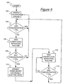
- a method according with the present invention starts at block 100.
- fuel management controller 24 operates gas sensors 22a-d to sample interior spaces within vehicle 10.
- the inventors of the present invention have determined that silicon micromachined gas sensors produced by Makel Engineering of Chico, CA, and having the model designation 02HDS021 are useful for practicing this invention.
- the measured concentrations of fugitive fuel gas are matched with a lower concentration threshold, CG1.
- the routine continues sampling at block 102. If however, the concentration exceeds CG1 at block 104, the routine moves to block 106 wherein a lower level mitigation routine is run.
- the lower level mitigation routine at block 106 includes opening movable glazing such as moon roof 46 or side windows 52, discontinuing high voltage charging of traction battery 14, and alerting the driver that fugitive fuel has been detected. Also, fuel tank enclosure fans 84 and battery enclosure fans 80 will be turned on. If a leak is detected in the passenger cabin, climate control fan 66 will be operated. If fugitive fuel gas is detected in the engine compartment, engine cooling fan 64 will be operated, and climate control fan 66 will be disabled. Also, vehicle refuelling will be prevented.
- the routine moves to block 108 wherein the measured gas concentration from sensors 22a-d is compared with a upper threshold CG2. If the gas concentration is not greater than CG2, the lower level mitigation routine will continue, until the concentration of gas drops below threshold CG1. If at block 108, the gas concentration exceeds CG2, the routine moves to block 110 wherein the prime mover 20 will be disabled by cutting off fuel by means of fuel cut-off valves 58a, b and c. This will serve to mitigate any fuel system integrity problem existing in fuel line 16 which conveys either gas or liquid between fuel tank 12 and prime mover 20, as well as any fuel handling problem located within the prime mover.
- fuel management controller 24 moves to block 112, where a higher level mitigation routine is run.
- This high level routine includes such steps as making certain that fuel tank solenoid valves 58 a, b and c are closed under all conditions, and also includes maintaining the operation of vent fans 80 and 84. Once fuel solenoid valves 58a-c are closed, they cannot be reopened until a manual reset is accomplished by the vehicle's operator.
- the routine of FIG. 5 continues with the running of the higher level mitigation routine until the concentration of fugitive gas is below CG2. If the measured concentration of fuel gas is below CG2 at block 112, the routine moves to block 104 and continues with a comparison of the measured gas concentration with CG11.
- the method of FIG. 5 preferably runs whenever vehicle 10 has fuel on board.
Landscapes
- Engineering & Computer Science (AREA)
- Mechanical Engineering (AREA)
- Chemical & Material Sciences (AREA)
- General Engineering & Computer Science (AREA)
- Combustion & Propulsion (AREA)
- Chemical Kinetics & Catalysis (AREA)
- General Chemical & Material Sciences (AREA)
- Oil, Petroleum & Natural Gas (AREA)
- Physics & Mathematics (AREA)
- Thermal Sciences (AREA)
- Life Sciences & Earth Sciences (AREA)
- Biomedical Technology (AREA)
- Atmospheric Sciences (AREA)
- Health & Medical Sciences (AREA)
- Environmental & Geological Engineering (AREA)
- Cooling, Air Intake And Gas Exhaust, And Fuel Tank Arrangements In Propulsion Units (AREA)
- Output Control And Ontrol Of Special Type Engine (AREA)
- Control Of Vehicle Engines Or Engines For Specific Uses (AREA)
- Combined Controls Of Internal Combustion Engines (AREA)
Claims (9)
- Système de gestion de carburant gazeux pour un véhicule automobile (10) doté d'un habitacle à passagers et d'un moteur principal (20), ledit système de gestion de carburant comprenant :un réservoir de stockage de carburant gazeux (12) ;une canalisation de carburant (16) destinée au transfert du dit carburant gazeux entre ledit réservoir de stockage (12) et ledit moteur principal (20), ladite canalisation de carburant (16) étant pourvue d'au moins une vanne à commande électronique (58) pour contrôler l'écoulement de carburant gazeux dans la canalisation de carburant (16) ;au moins un capteur de gaz (22) destiné à détecter la présence de carburant gazeux à l'extérieur d'au moins un des composants constitués par ledit réservoir de stockage, ladite canalisation de carburant et ledit moteur principal, ledit capteur émettant un signal de détection de gaz en cas de détection d'une concentration de carburant gazeux supérieure à un seuil prédéterminé ; etun contrôleur de gestion de carburant (24) connecté de façon opérationnelle à ladite vanne à commande électronique (58) et au dit capteur de gaz (22), ledit contrôleur (24) fermant ladite vanne à commande électronique (58) dans le cas où le capteur de gaz (22) émet un signal de détection de gaz ;caractérisé en ce que ledit moteur principal (20) comprend un moteur à combustion interne (26) relié à un ensemble moteur de traction/alternateur (34) et à une transmission (30) ; et
en ce que ledit contrôleur de gestion de carburant (24) empêche la recharge d'une batterie de traction (14) en présence du dit signal de détection de gaz. - Système de gestion de carburant gazeux selon la revendication 1 dans lequel ledit contrôleur de gestion de carburant (24) ferme ladite vanne à commande électronique (58) en présence du dit signal de détection de gaz et permet en outre la poursuite du fonctionnement du dit véhicule avec ledit ensemble moteur de traction/alternateur (34).
- Système de gestion de carburant gazeux selon la revendication 1 ou 2 comprenant en outre au moins un circulateur atmosphérique (28) actionné par ledit contrôleur de gestion de carburant (24) en réponse à un signal de détection de gaz provenant du dit capteur de gaz.
- Système de gestion de carburant gazeux selon l'une des revendications précédentes dans lequel ledit contrôleur de gestion de carburant (24) ouvre au moins une vitre (52) ou un toit ouvrant (46) dans ledit habitacle à passagers en réponse à un signal de détection de gaz provenant du dit capteur de gaz.
- Système de gestion de carburant gazeux selon l'une des revendications précédentes dans lequel ledit carburant gazeux est de l'hydrogène, du gaz naturel ou du gaz de pétrole liquéfié.
- Système de gestion de carburant gazeux selon l'une des revendications précédentes comprenant en outre un système de mise en garde destiné à alerter un conducteur du dit véhicule en présence d'un signal de détection de gaz.
- Système de gestion de carburant gazeux selon l'une des revendications précédentes dans lequel ledit capteur de détection gaz (22) se trouve dans au moins un des emplacements suivants, à savoir une enceinte dans laquelle est monté ledit réservoir de stockage de carburant, un compartiment dans lequel se trouve ledit moteur principal, ledit habitacle à passagers et une enceinte dans laquelle se trouve une batterie de traction (14).
- Système de gestion de carburant gazeux selon l'une des revendications précédentes comprenant en outre au moins un conduit de ventilation ayant une première extrémité raccordée à une enceinte dans laquelle est monté ledit réservoir de stockage de carburant et une deuxième extrémité raccordée à un extracteur d'air monté sur une surface externe de ladite automobile, dispositions grâce auxquelles tout carburant gazeux entrant dans ladite enceinte du dit réservoir de stockage de carburant est extrait de ladite enceinte.
- Système de gestion de carburant gazeux selon l'une des revendications précédentes comprenant en outre au moins une ouverture de ventilation formée dans une partie supérieure d'un compartiment dans lequel se trouve ledit moteur principal, disposition grâce à laquelle tout carburant gazeux entrant dans ledit compartiment du dit moteur principal est extrait du dit compartiment.
Applications Claiming Priority (3)
| Application Number | Priority Date | Filing Date | Title |
|---|---|---|---|
| US49030703P | 2003-07-25 | 2003-07-25 | |
| US54961704P | 2004-03-03 | 2004-03-03 | |
| PCT/US2004/020132 WO2005016674A1 (fr) | 2003-07-25 | 2004-06-24 | Systeme de gestion de carburant gazeux pour automobile |
Publications (3)
| Publication Number | Publication Date |
|---|---|
| EP1648723A1 EP1648723A1 (fr) | 2006-04-26 |
| EP1648723A4 EP1648723A4 (fr) | 2006-11-15 |
| EP1648723B1 true EP1648723B1 (fr) | 2007-08-29 |
Family
ID=34197913
Family Applications (1)
| Application Number | Title | Priority Date | Filing Date |
|---|---|---|---|
| EP04755957A Expired - Lifetime EP1648723B1 (fr) | 2003-07-25 | 2004-06-24 | Systeme de gestion de carburant gazeux pour automobile |
Country Status (6)
| Country | Link |
|---|---|
| US (1) | US7970528B2 (fr) |
| EP (1) | EP1648723B1 (fr) |
| JP (1) | JP2007500808A (fr) |
| KR (1) | KR20060083407A (fr) |
| DE (1) | DE602004008642T2 (fr) |
| WO (1) | WO2005016674A1 (fr) |
Families Citing this family (22)
| Publication number | Priority date | Publication date | Assignee | Title |
|---|---|---|---|---|
| JP4956906B2 (ja) * | 2005-03-29 | 2012-06-20 | トヨタ自動車株式会社 | 燃料電池システムおよび水素漏れ検出方法 |
| EP2119585B1 (fr) * | 2007-03-06 | 2012-08-01 | Toyota Jidosha Kabushiki Kaisha | Véhicule |
| JP2010163908A (ja) * | 2009-01-13 | 2010-07-29 | Toyota Motor Corp | アンモニア燃焼内燃機関 |
| US8214129B2 (en) * | 2009-05-13 | 2012-07-03 | Ford Global Technologies, Llc | Distinguishing the fuel admitted to a fuel system |
| DE102011001992A1 (de) * | 2011-04-12 | 2012-10-18 | Dr. Ing. H.C. F. Porsche Aktiengesellschaft | Klimabox |
| PL2788215T3 (pl) | 2011-12-07 | 2020-06-15 | Agility Fuel Systems Llc | Systemy i sposoby monitorowania i kontrolowania układów paliwowych |
| CN103171407A (zh) * | 2011-12-20 | 2013-06-26 | 上海汽车集团股份有限公司 | 氢气强排系统和氢气强排方法 |
| US9133783B2 (en) * | 2012-03-07 | 2015-09-15 | Ford Global Technologies, Llc | Method and system for estimating fuel system integrity |
| US10040680B2 (en) | 2012-05-03 | 2018-08-07 | Daniel McNicholas | Compressed natural gas vehicle safety system and method |
| US8662235B2 (en) | 2012-05-03 | 2014-03-04 | Daniel McNicholas | Compressed natural gas vehicle safety system and method |
| US9228516B2 (en) * | 2012-09-04 | 2016-01-05 | GM Global Technology Operations LLC | Fuel pump prime activated by door sensor |
| US20140365100A1 (en) * | 2013-06-11 | 2014-12-11 | Gary J. Speier | Vehicle control based on sensed enviornmental condition |
| DE102013015514B4 (de) * | 2013-09-19 | 2017-11-23 | Daimler Ag | Vorrichtung zum Speichern von Energie |
| US20140182561A1 (en) * | 2013-09-25 | 2014-07-03 | Eghosa Gregory Ibizugbe, JR. | Onboard CNG/CFG Vehicle Refueling and Storage Systems and Methods |
| JP6189693B2 (ja) * | 2013-09-26 | 2017-08-30 | トヨタ自動車株式会社 | 燃料電池搭載車両 |
| US9404429B2 (en) * | 2013-09-27 | 2016-08-02 | Electro-Motive Diesel, Inc. | Control system for dual-fuel engine |
| US9579969B2 (en) * | 2014-07-25 | 2017-02-28 | Oshkosh Corporation | Refuse vehicle having tailgate-mounted CNG tanks |
| US10054096B2 (en) * | 2014-09-25 | 2018-08-21 | N4 Innovations, Llc | Vehicle occupant protection and engine idle reduction system |
| KR101694030B1 (ko) * | 2015-07-09 | 2017-01-09 | 현대자동차주식회사 | 플러그인 하이브리드 차량의 주유 및 충전 관리 시스템 |
| CN105840348A (zh) * | 2016-03-29 | 2016-08-10 | 成都科力夫科技有限公司 | 一种用于双燃料汽车的燃气喷射系统 |
| CN108757226B (zh) * | 2018-05-22 | 2024-01-23 | 内蒙古科技大学 | 一种车用汽油油气回收监测装置及其监测方法 |
| JP7853441B2 (ja) * | 2022-11-16 | 2026-04-28 | 日本国土開発株式会社 | 移動装置及び移動方法 |
Family Cites Families (16)
| Publication number | Priority date | Publication date | Assignee | Title |
|---|---|---|---|---|
| JPH01295704A (ja) * | 1988-05-23 | 1989-11-29 | Mizoguchi Tekkosho:Kk | 切削工具ホルダー用コレット |
| DE3907049A1 (de) * | 1989-03-04 | 1990-09-13 | Bayerische Motoren Werke Ag | Fahrzeug mit einem sicherheitssystem |
| US5501200A (en) * | 1994-06-28 | 1996-03-26 | Bogartz; Stuart P. | Compressed gas fueling system |
| JP3391423B2 (ja) * | 1994-09-30 | 2003-03-31 | 本田技研工業株式会社 | 自動車の漏洩圧縮燃料ガス排出用管先端部の取付け構造 |
| JP3707522B2 (ja) * | 1998-08-21 | 2005-10-19 | 日産自動車株式会社 | 蒸発燃料処理装置の診断装置 |
| JP3409732B2 (ja) * | 1999-04-12 | 2003-05-26 | トヨタ自動車株式会社 | 蒸発燃料処理装置 |
| US6609582B1 (en) * | 1999-04-19 | 2003-08-26 | Delphi Technologies, Inc. | Power generation system and method |
| BE1012708A3 (fr) * | 1999-06-07 | 2001-02-06 | Solvay | Systeme a carburant pour vehicule. |
| US6290594B1 (en) | 2000-08-16 | 2001-09-18 | Ford Global Tech., Inc. | System and method for ventilating hydrogen gas from a vehicle |
| JP4027044B2 (ja) * | 2001-01-16 | 2007-12-26 | 本田技研工業株式会社 | 車両の気体燃料ガス排出構造 |
| JP3540286B2 (ja) * | 2001-04-13 | 2004-07-07 | 株式会社デンソー | 燃料蒸気処理装置 |
| US6446616B1 (en) * | 2001-11-02 | 2002-09-10 | Ford Global Technologies, Inc. | Vent system for gaseous fueled vehicle |
| DE10252225A1 (de) * | 2002-11-11 | 2004-05-27 | Robert Bosch Gmbh | Verfahren zur Bestimmung des Kraftstoff-Dampfdrucks in einem Kraftfahrzeug mit Bordmitteln |
| JP2004360553A (ja) * | 2003-06-04 | 2004-12-24 | Suzuki Motor Corp | 内燃機関の蒸発燃料制御装置 |
| US7107759B2 (en) * | 2003-07-11 | 2006-09-19 | Denso Corporation | Apparatus for reducing hydrocarbon emission of internal combustion engine |
| JP4115404B2 (ja) * | 2003-12-19 | 2008-07-09 | 三菱電機株式会社 | 自動車用燃料供給装置における燃料蒸発ガスの漏れ出し検出機構、および、検出方法 |
-
2004
- 2004-06-24 WO PCT/US2004/020132 patent/WO2005016674A1/fr not_active Ceased
- 2004-06-24 JP JP2006521080A patent/JP2007500808A/ja active Pending
- 2004-06-24 US US10/566,029 patent/US7970528B2/en active Active
- 2004-06-24 EP EP04755957A patent/EP1648723B1/fr not_active Expired - Lifetime
- 2004-06-24 KR KR1020067001606A patent/KR20060083407A/ko not_active Ceased
- 2004-06-24 DE DE200460008642 patent/DE602004008642T2/de not_active Expired - Fee Related
Also Published As
| Publication number | Publication date |
|---|---|
| WO2005016674A1 (fr) | 2005-02-24 |
| DE602004008642T2 (de) | 2008-06-05 |
| KR20060083407A (ko) | 2006-07-20 |
| EP1648723A4 (fr) | 2006-11-15 |
| JP2007500808A (ja) | 2007-01-18 |
| US7970528B2 (en) | 2011-06-28 |
| US20070256737A1 (en) | 2007-11-08 |
| DE602004008642D1 (de) | 2007-10-11 |
| EP1648723A1 (fr) | 2006-04-26 |
Similar Documents
| Publication | Publication Date | Title |
|---|---|---|
| EP1648723B1 (fr) | Systeme de gestion de carburant gazeux pour automobile | |
| US10850587B2 (en) | System and method for evaporative emissions detection | |
| US6782914B2 (en) | Gaseous fuel discharging structure for vehicle | |
| KR940010730B1 (ko) | 자동차 엔진용 페일 세이프 시스템 | |
| US10100782B2 (en) | Systems and methods for vehicle evaporative emissions system diagnostics | |
| US5390643A (en) | Pressure control apparatus for fuel tank | |
| JPH0932659A (ja) | 燃料蒸発ガス排出抑止システムの故障診断装置 | |
| RU148357U1 (ru) | Вытяжная система транспортного средства | |
| US20150275781A1 (en) | Engine fuel enhancement management system | |
| US20190383239A1 (en) | Methods and system for conducting an engine system diagnostic based on ambient noise | |
| JPH02290758A (ja) | 安全システムを備えた車両 | |
| US20200232870A1 (en) | Method and system for fuel system leak detection | |
| US20210370762A1 (en) | Electronic fuel tank system having cam actuated venting with canister line isolation | |
| CN111688476A (zh) | 用于减少鞍形燃料箱减压时间的系统和方法 | |
| CN107839474B (zh) | 用于控制燃料储箱系统内的压强的方法 | |
| CN203854563U (zh) | 一种汽车燃气安全控制系统 | |
| US6345604B1 (en) | Electronically controlled throttle valve with commanded default position for the throttle valve of an internal combustion engine | |
| US10982632B1 (en) | Refueling control systems and methods for pressurized vehicle fuel systems | |
| CN1795112A (zh) | 汽车的气体燃料管理系统 | |
| US20100263730A1 (en) | Method and device for controlling an internal combustion engine | |
| KR102719105B1 (ko) | 차량용 연료계통의 리크진단시스템 및 리크진단방법 | |
| EP1361100B1 (fr) | Système et procédé pour la surveillance des fuites dans une commande d'émission des vapeurs de carburant | |
| US12516641B2 (en) | Apparatus and method for controlling fuel system of vehicle | |
| JP2001140706A (ja) | 蒸発燃料系穴開き故障診断装置 | |
| DeRonne et al. | The development and implementation of an engine off natural vacuum test for diagnosing small leaks in evaporative emissions systems |
Legal Events
| Date | Code | Title | Description |
|---|---|---|---|
| PUAI | Public reference made under article 153(3) epc to a published international application that has entered the european phase |
Free format text: ORIGINAL CODE: 0009012 |
|
| 17P | Request for examination filed |
Effective date: 20060112 |
|
| AK | Designated contracting states |
Kind code of ref document: A1 Designated state(s): DE FR GB SE |
|
| DAX | Request for extension of the european patent (deleted) | ||
| RBV | Designated contracting states (corrected) |
Designated state(s): DE FR GB SE |
|
| A4 | Supplementary search report drawn up and despatched |
Effective date: 20061016 |
|
| RIC1 | Information provided on ipc code assigned before grant |
Ipc: B60H 3/06 20060101AFI20050301BHEP Ipc: B60H 1/24 20060101ALI20061010BHEP |
|
| GRAP | Despatch of communication of intention to grant a patent |
Free format text: ORIGINAL CODE: EPIDOSNIGR1 |
|
| 17Q | First examination report despatched |
Effective date: 20070131 |
|
| GRAS | Grant fee paid |
Free format text: ORIGINAL CODE: EPIDOSNIGR3 |
|
| GRAA | (expected) grant |
Free format text: ORIGINAL CODE: 0009210 |
|
| AK | Designated contracting states |
Kind code of ref document: B1 Designated state(s): DE FR GB SE |
|
| REG | Reference to a national code |
Ref country code: GB Ref legal event code: FG4D |
|
| REF | Corresponds to: |
Ref document number: 602004008642 Country of ref document: DE Date of ref document: 20071011 Kind code of ref document: P |
|
| EN | Fr: translation not filed | ||
| PG25 | Lapsed in a contracting state [announced via postgrant information from national office to epo] |
Ref country code: SE Free format text: LAPSE BECAUSE OF FAILURE TO SUBMIT A TRANSLATION OF THE DESCRIPTION OR TO PAY THE FEE WITHIN THE PRESCRIBED TIME-LIMIT Effective date: 20071129 |
|
| PLBE | No opposition filed within time limit |
Free format text: ORIGINAL CODE: 0009261 |
|
| STAA | Information on the status of an ep patent application or granted ep patent |
Free format text: STATUS: NO OPPOSITION FILED WITHIN TIME LIMIT |
|
| 26N | No opposition filed |
Effective date: 20080530 |
|
| GBPC | Gb: european patent ceased through non-payment of renewal fee |
Effective date: 20080624 |
|
| PG25 | Lapsed in a contracting state [announced via postgrant information from national office to epo] |
Ref country code: DE Free format text: LAPSE BECAUSE OF NON-PAYMENT OF DUE FEES Effective date: 20090101 |
|
| PG25 | Lapsed in a contracting state [announced via postgrant information from national office to epo] |
Ref country code: GB Free format text: LAPSE BECAUSE OF NON-PAYMENT OF DUE FEES Effective date: 20080624 |
|
| PG25 | Lapsed in a contracting state [announced via postgrant information from national office to epo] |
Ref country code: FR Free format text: LAPSE BECAUSE OF FAILURE TO SUBMIT A TRANSLATION OF THE DESCRIPTION OR TO PAY THE FEE WITHIN THE PRESCRIBED TIME-LIMIT Effective date: 20080425 |