EP1649155B1 - Volet d'air automatique pour moteur - Google Patents
Volet d'air automatique pour moteur Download PDFInfo
- Publication number
- EP1649155B1 EP1649155B1 EP04778188A EP04778188A EP1649155B1 EP 1649155 B1 EP1649155 B1 EP 1649155B1 EP 04778188 A EP04778188 A EP 04778188A EP 04778188 A EP04778188 A EP 04778188A EP 1649155 B1 EP1649155 B1 EP 1649155B1
- Authority
- EP
- European Patent Office
- Prior art keywords
- engine
- choke
- responsive member
- thermally responsive
- thermally conductive
- Prior art date
- Legal status (The legal status is an assumption and is not a legal conclusion. Google has not performed a legal analysis and makes no representation as to the accuracy of the status listed.)
- Expired - Lifetime
Links
Images











Classifications
-
- F—MECHANICAL ENGINEERING; LIGHTING; HEATING; WEAPONS; BLASTING
- F02—COMBUSTION ENGINES; HOT-GAS OR COMBUSTION-PRODUCT ENGINE PLANTS
- F02D—CONTROLLING COMBUSTION ENGINES
- F02D11/00—Arrangements for, or adaptations to, non-automatic engine control initiation means, e.g. operator initiated
- F02D11/02—Arrangements for, or adaptations to, non-automatic engine control initiation means, e.g. operator initiated characterised by hand, foot, or like operator controlled initiation means
-
- F—MECHANICAL ENGINEERING; LIGHTING; HEATING; WEAPONS; BLASTING
- F01—MACHINES OR ENGINES IN GENERAL; ENGINE PLANTS IN GENERAL; STEAM ENGINES
- F01N—GAS-FLOW SILENCERS OR EXHAUST APPARATUS FOR MACHINES OR ENGINES IN GENERAL; GAS-FLOW SILENCERS OR EXHAUST APPARATUS FOR INTERNAL-COMBUSTION ENGINES
- F01N1/00—Silencing apparatus characterised by method of silencing
-
- F—MECHANICAL ENGINEERING; LIGHTING; HEATING; WEAPONS; BLASTING
- F01—MACHINES OR ENGINES IN GENERAL; ENGINE PLANTS IN GENERAL; STEAM ENGINES
- F01N—GAS-FLOW SILENCERS OR EXHAUST APPARATUS FOR MACHINES OR ENGINES IN GENERAL; GAS-FLOW SILENCERS OR EXHAUST APPARATUS FOR INTERNAL-COMBUSTION ENGINES
- F01N5/00—Exhaust or silencing apparatus combined or associated with devices profiting by exhaust energy
- F01N5/02—Exhaust or silencing apparatus combined or associated with devices profiting by exhaust energy the devices using heat
-
- F—MECHANICAL ENGINEERING; LIGHTING; HEATING; WEAPONS; BLASTING
- F02—COMBUSTION ENGINES; HOT-GAS OR COMBUSTION-PRODUCT ENGINE PLANTS
- F02D—CONTROLLING COMBUSTION ENGINES
- F02D11/00—Arrangements for, or adaptations to, non-automatic engine control initiation means, e.g. operator initiated
- F02D11/04—Arrangements for, or adaptations to, non-automatic engine control initiation means, e.g. operator initiated characterised by mechanical control linkages
-
- F—MECHANICAL ENGINEERING; LIGHTING; HEATING; WEAPONS; BLASTING
- F02—COMBUSTION ENGINES; HOT-GAS OR COMBUSTION-PRODUCT ENGINE PLANTS
- F02D—CONTROLLING COMBUSTION ENGINES
- F02D17/00—Controlling engines by cutting out individual cylinders; Rendering engines inoperative or idling
- F02D17/04—Controlling engines by cutting out individual cylinders; Rendering engines inoperative or idling rendering engines inoperative or idling, e.g. caused by abnormal conditions
-
- F—MECHANICAL ENGINEERING; LIGHTING; HEATING; WEAPONS; BLASTING
- F02—COMBUSTION ENGINES; HOT-GAS OR COMBUSTION-PRODUCT ENGINE PLANTS
- F02D—CONTROLLING COMBUSTION ENGINES
- F02D9/00—Controlling engines by throttling air or fuel-and-air induction conduits or exhaust conduits
- F02D9/02—Controlling engines by throttling air or fuel-and-air induction conduits or exhaust conduits concerning induction conduits
-
- F—MECHANICAL ENGINEERING; LIGHTING; HEATING; WEAPONS; BLASTING
- F02—COMBUSTION ENGINES; HOT-GAS OR COMBUSTION-PRODUCT ENGINE PLANTS
- F02M—SUPPLYING COMBUSTION ENGINES IN GENERAL WITH COMBUSTIBLE MIXTURES OR CONSTITUENTS THEREOF
- F02M1/00—Carburettors with means for facilitating engine's starting or its idling below operational temperatures
- F02M1/02—Carburettors with means for facilitating engine's starting or its idling below operational temperatures the means to facilitate starting or idling being chokes for enriching fuel-air mixture
-
- F—MECHANICAL ENGINEERING; LIGHTING; HEATING; WEAPONS; BLASTING
- F02—COMBUSTION ENGINES; HOT-GAS OR COMBUSTION-PRODUCT ENGINE PLANTS
- F02M—SUPPLYING COMBUSTION ENGINES IN GENERAL WITH COMBUSTIBLE MIXTURES OR CONSTITUENTS THEREOF
- F02M1/00—Carburettors with means for facilitating engine's starting or its idling below operational temperatures
- F02M1/08—Carburettors with means for facilitating engine's starting or its idling below operational temperatures the means to facilitate starting or idling becoming operative or inoperative automatically
- F02M1/10—Carburettors with means for facilitating engine's starting or its idling below operational temperatures the means to facilitate starting or idling becoming operative or inoperative automatically dependent on engine temperature, e.g. having thermostat
-
- F—MECHANICAL ENGINEERING; LIGHTING; HEATING; WEAPONS; BLASTING
- F01—MACHINES OR ENGINES IN GENERAL; ENGINE PLANTS IN GENERAL; STEAM ENGINES
- F01P—COOLING OF MACHINES OR ENGINES IN GENERAL; COOLING OF INTERNAL-COMBUSTION ENGINES
- F01P5/00—Pumping cooling-air or liquid coolants
- F01P5/02—Pumping cooling-air; Arrangements of cooling-air pumps, e.g. fans or blowers
-
- F—MECHANICAL ENGINEERING; LIGHTING; HEATING; WEAPONS; BLASTING
- F02—COMBUSTION ENGINES; HOT-GAS OR COMBUSTION-PRODUCT ENGINE PLANTS
- F02D—CONTROLLING COMBUSTION ENGINES
- F02D9/00—Controlling engines by throttling air or fuel-and-air induction conduits or exhaust conduits
- F02D9/02—Controlling engines by throttling air or fuel-and-air induction conduits or exhaust conduits concerning induction conduits
- F02D2009/0201—Arrangements; Control features; Details thereof
- F02D2009/0208—Arrangements; Control features; Details thereof for small engines
-
- F—MECHANICAL ENGINEERING; LIGHTING; HEATING; WEAPONS; BLASTING
- F02—COMBUSTION ENGINES; HOT-GAS OR COMBUSTION-PRODUCT ENGINE PLANTS
- F02D—CONTROLLING COMBUSTION ENGINES
- F02D9/00—Controlling engines by throttling air or fuel-and-air induction conduits or exhaust conduits
- F02D9/02—Controlling engines by throttling air or fuel-and-air induction conduits or exhaust conduits concerning induction conduits
- F02D2009/0201—Arrangements; Control features; Details thereof
- F02D2009/0216—Arrangements; Control features; Details thereof of the air-vane type
-
- F—MECHANICAL ENGINEERING; LIGHTING; HEATING; WEAPONS; BLASTING
- F02—COMBUSTION ENGINES; HOT-GAS OR COMBUSTION-PRODUCT ENGINE PLANTS
- F02D—CONTROLLING COMBUSTION ENGINES
- F02D9/00—Controlling engines by throttling air or fuel-and-air induction conduits or exhaust conduits
- F02D9/02—Controlling engines by throttling air or fuel-and-air induction conduits or exhaust conduits concerning induction conduits
- F02D2009/0201—Arrangements; Control features; Details thereof
- F02D2009/0222—Exhaust gas temperature
-
- F—MECHANICAL ENGINEERING; LIGHTING; HEATING; WEAPONS; BLASTING
- F02—COMBUSTION ENGINES; HOT-GAS OR COMBUSTION-PRODUCT ENGINE PLANTS
- F02D—CONTROLLING COMBUSTION ENGINES
- F02D9/00—Controlling engines by throttling air or fuel-and-air induction conduits or exhaust conduits
- F02D9/02—Controlling engines by throttling air or fuel-and-air induction conduits or exhaust conduits concerning induction conduits
- F02D2009/0201—Arrangements; Control features; Details thereof
- F02D2009/0264—Arrangements; Control features; Details thereof in which movement is transmitted through a spring
-
- F—MECHANICAL ENGINEERING; LIGHTING; HEATING; WEAPONS; BLASTING
- F02—COMBUSTION ENGINES; HOT-GAS OR COMBUSTION-PRODUCT ENGINE PLANTS
- F02D—CONTROLLING COMBUSTION ENGINES
- F02D9/00—Controlling engines by throttling air or fuel-and-air induction conduits or exhaust conduits
- F02D9/02—Controlling engines by throttling air or fuel-and-air induction conduits or exhaust conduits concerning induction conduits
- F02D2009/0201—Arrangements; Control features; Details thereof
- F02D2009/0267—Arrangements; Control features; Details thereof for simultaneous action of a governor and an accelerator lever on the throttle
-
- Y—GENERAL TAGGING OF NEW TECHNOLOGICAL DEVELOPMENTS; GENERAL TAGGING OF CROSS-SECTIONAL TECHNOLOGIES SPANNING OVER SEVERAL SECTIONS OF THE IPC; TECHNICAL SUBJECTS COVERED BY FORMER USPC CROSS-REFERENCE ART COLLECTIONS [XRACs] AND DIGESTS
- Y02—TECHNOLOGIES OR APPLICATIONS FOR MITIGATION OR ADAPTATION AGAINST CLIMATE CHANGE
- Y02T—CLIMATE CHANGE MITIGATION TECHNOLOGIES RELATED TO TRANSPORTATION
- Y02T10/00—Road transport of goods or passengers
- Y02T10/10—Internal combustion engine [ICE] based vehicles
- Y02T10/12—Improving ICE efficiencies
Definitions
- This invention relates to choke assemblies for an internal combustion engine. More specifically, the invention relates to an automatic choke assembly.
- the choke must remain open to start the engine and to prevent the engine from stumbling or stalling.
- the choke valve is opened too soon, the engine stalls because the fuel-air mixture is not rich enough to sustain the reaction. If the choke remains on too long, the engine may also stumble and excessive hydrocarbon emissions and fouling of the spark plugs can occur.
- US 3,315,949 is considered as the closest prior art, and discloses an engine according to the preamble of claim 1, and a method according to the preamble of claim 20.
- the present invention provides an engine in accordance with independent claim 1, and a method in accordance with independent claim 20. Further preferred embodiments are given in the dependent claims.
- the present invention provides an automatic choke assembly for an internal combustion engine.
- One construction of the engine includes a choke valve and a choke operating device that operates the choke valve.
- the engine also includes a thermally conductive assembly in direct contact with exhaust gases produced by the engine, and a thermally responsive member in thermal communication with the thermally conductive assembly such that the thermally conductive assembly transfers heat from the exhaust gases to the thermally responsive member.
- the engine also includes a mechanism responsive to the thermally responsive member to cause the choke valve to remain in at least a partially open position during engine starting when the thermally responsive member senses a temperature above a predetermined temperature.
- the thermally conductive assembly also comprises a thermally conductive element including a first portion, a second portion, and a bridge connecting the first portion to the second portion.
- the thermally responsive member is coupled to the first portion, and wherein the second portion includes an exhaust flange which is at least partially surrounding the direct path of exhaust gases and adapted to cooperate with the output of an exhaust manifold and/or a muffler of the engine.
- the choke operating device includes an air vane that moves as a function of the engine speed.
- the thermally responsive member is a bimetallic coil.
- the thermally conductive assembly at least partially surrounds the path of the exhaust gases.
- the mechanism includes a stop lever coupled to the thermally responsive member, the stop lever interacting with the choke operating device.
- the present invention also provides a method of operating a choke in an internal combustion engine using exhaust heat including placing a thermally conductive assembly in direct contact with exhaust gases produced by the engine, transmitting heat from the exhaust gases to the thermally conductive assembly through a solid material, and transmitting heat from the thermally conductive assembly to a thermally responsive member in thermal contact with the thermally conductive element.
- the method also includes providing a linkage between the thermally responsive member and a choke operating device, and preventing the choke valve from closing completely during restarts of the engine when the temperature of the engine has reached a predetermined temperature.
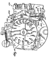
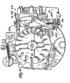
- FIG. 1 illustrates an internal combustion engine 10 according to one embodiment of the present invention.
- the engine 10 includes a choke valve assembly 14 that includes a choke valve 18 (shown in FIG. 5 ) and a choke operating device.
- the choke operating device may operate the choke valve 18 as a function of the speed of the engine 10.
- the choke operating device is an air vane 22.
- the choke operating device could include centrifugally mounted flyweights of an engine governor or an engine manifold pressure sensor.
- the engine 10 also includes a throttle linkage 20.
- the air vane 22 moves in response to air flow produced by a fan 26 coupled to the engine crankshaft, and rotates with the crankshaft. In this way, the air vane 22 operates to open and/or close the choke valve as a function of the engine speed. Since the air vane 22 reacts to engine speeds, if the engine attempts to stall, the force on the air vane 22 is reduced as the engine speed drops. As a result, the choke valve 18 begins to close to enrich the fuel-air mix until the engine recovers.
- the design of the air vane 22 also provides greater torque as the engine speed ramps up after starting, helping to open the choke valve 18 more quickly after start-up, and reducing the exhaust produced by the fuel-rich start-up conditions.
- the air vane 22 is connected to the choke valve 18 via a choke linkage 30.
- the choke linkage 30 includes a first arm 34, a second arm 38, and a biasing member 42.
- the biasing member 42 is attached to an engine bracket 46 and biases the choke valve 18 to the closed position.
- the choke linkage 30 also includes a choke lever 50 adapted to operate the choke valve 18. The greater torque of the air vane 22 at low speeds also allows a stronger biasing member 42 to be used to bias the choke valve 18 closed when the engine is cold and helps prevent debris build-up from interfering with the closing of the valve 18.
- the engine 10 also includes an automatic choke apparatus 54 and an engine muffler 58 attached to the exhaust manifold (not shown) of the engine 10.
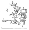
- the automatic choke apparatus 54 includes a mechanism 62 and a thermally conductive assembly 66. The details of the thermally conductive assembly 66 will be described in detail below with respect to FIG. 2 .
- the mechanism 62 includes a linkage that includes a stop lever 78 coupled to the thermally conductive assembly 66, a tab 82 coupled to the air vane 22, and the choke linkage 30. The function of the linkage will be descried in greater detail below.
- the thermally conductive assembly 66 includes a cover 86 located adjacent the muffler 58.
- the cover 86 may be formed of any appropriate material, such as aluminized steel, brass, ceramic material, or nylon, and in some embodiments can include a conductive material.
- the thermally conductive assembly 66 includes a conductive element 90 that is coupled to the engine housing.
- the conductive element 90 may be formed of stamped metal, such as an aluminum alloy. In the illustrated embodiment, the conductive element 90 is formed of a standard 380 die cast aluminum alloy.
- the conductive element 90 also includes an exhaust flange 88 adapted to cooperate with the output of the exhaust manifold and/or muffler 58 of the engine 10.
- the thermally conductive assembly 66 at least partially surrounds the direct path of the exhaust gases from the engine, thereby placing the thermally conductive assembly 66 in direct contact with the exhaust gases. This placement in direct contact with the gases allows for near instantaneous response of the automatic choke apparatus 54 in response to engine temperature to keep the choke valve 18 at least partially open during warm restarts.
- the thermally conductive assembly 66 at least partially surrounds the exhaust manifold of the engine.
- the conductive element 90 further includes a first portion 92 and a second portion 93.
- the exhaust flange 88 is connected to the second portion 93 of the conductive element 90.
- the conductive element 90 also includes a bridge 110 extending between the first and second portions 92, 93. As illustrated in FIG. 2 , the bridge 110 has a width W that is preferably less than the width of either the first or second portions 92, 93 of the conductive element First and second gaskets 114, 116 are coupled to either side of the exhaust flange 88 to ensure a secure fit between the conductive element 90 and the exhaust manifold and to reduce vibrations in the conductive element 90.
- the thermally conductive assembly 66 Considerations of the volume and shape of the thermally conductive assembly 66 are important to obtain the most efficient heat transfer through the thermally conductive assembly. Both increased surface area and increased mass contribute to heat loss in the thermally conductive assembly 66, and thus less heat transferred.
- the conductive element 90 (including the widths of the first portion 92, second portion 93, and bridge 110), cover 86, and exhaust flange 88 are selected such that the amount of surface area, the shape, the mass, and the conductive material together achieve the desired amount of heat transfer from the exhaust gases to the thermally conductive assembly 66.
- the physical shape, mass, and materials of the thermally conductive assembly 66 are also optimized to create an ideal thermal conducting geometry to transfer heat through the thermally conductive assembly 66 to be proportional to the engine temperatures during starting, warm-up, and cool down.
- the geometry of the thermally conductive assembly 66 allows for rapid temperature rise and calibrated cool down to address the engine fueling requirements (or, the choking requirements).
- the physical configuration of the thermally conductive assembly 66 is not only important to help provide near instantaneous response of the automatic choke apparatus 54, it is also important to allow the choke valve 18 to close after an appropriate cool down period.
- the thermally conductive assembly 66 is configured not only for efficient heat conduction, but also for appropriately calibrated heat loss.
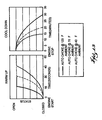
- FIG. 13 illustrates the desired time vs. temperature rise curves for an engine utilizing the automatic choke apparatus 54 described herein.
- the conductive element 90 includes a first aperture 94 that is configured to receive a mounting pin 98 that is coupled to the stop lever 78.
- the conductive element 90 also includes a second aperture 102 (best seen in FIG. 3 ) configured to receive a stop projection 106 that is coupled to the stop lever 78.
- the conductive element 90 also includes two stop tabs 108 that interact with the stop projection 106 to prevent the stop lever 78 from over-rotating in response to changes in the thermally conductive assembly 66.
- the thermally conductive assembly 66 also includes a thermally responsive member coupled to the conductive element 90.
- the thermally responsive member is a bimetallic coil 118.
- the thermally responsive member may be any appropriate thermal actuator, such as a wax motor, a thermally responsive wire, a bimetallic disk, plastics, etc.
- the placement of the thermally responsive device within the engine dictates which type of thermally responsive member is appropriate as conditions vary within the engine 10. Exhaust temperatures rise throughout engine use to very high levels (upward of 500 degrees Fahrenheit) and thus the thermally responsive member must be able to withstand extreme temperatures for long periods of time.
- Bimetallic coils can withstand the sustained high temperatures while providing quick (i.e., the coil is reactive to temperature changes) and accurate temperature measurement for actuating the choke.
- the bimetallic coil 118 may be formed of several known combinations of two metals having different coefficients of thermal expansion or contraction such that the bimetallic coil 118 either expands or contracts in response to the temperature changes in the engine 10.
- the bimetallic coil 118 is coupled between the cover 86 and the conductive element 90.
- a slot 120 in the mounting pin 98 grips the inner end 124 of the coil 118.
- a coil aperture 128 in the cover 86 receives a coil tab 132 to secure the coil 118.
- a clamp 136 is also coupled to the conductive element 90 to further anchor the cover 86 and the coil 118 to the thermally conductive assembly 66.
- the above described apparatus acts to automatically operate the choke valve 18 based upon the temperature of the engine 10.
- the bimetallic coil 118 acts as a thermostat in the engine 10 that assures that the choke valve 18 remains at least partially open when the engine 10 reaches a predetermined temperature to maximize fuel efficiency and starting performance in the engine 10. If you start the engine 10 when it is cold, the engine temperature needs to reach approximately one hundred eighty degrees to open the choke valve 18. The amount of time it takes for the engine to reach one hundred eighty degrees will depend on the ambient temperature of the engine before starting. Thus, the automatic choke apparatus 54 is self-adjusting to any particular use.
- the thermally conductive assembly 66 As the engine 10 produces exhaust gases, heat from those gases is conducted by the thermally conductive assembly 66 through a solid material, i.e., the exhaust flange 88, and transmitted to the coil 118 through thermal contact with the coil 118.
- a solid material i.e., the exhaust flange 88
- the word "solid” is defined to mean an object that is not a fluid or a gas.
- the heat from the exhaust gases is conducted through the molecules of a solid material, as opposed to through a gas or liquid.
- the solid material is the conductor of the heat.
- the increased temperature in the coil 118 causes the coil to expand or contract, resulting in rotation of the mounting pin 98 and the stop lever 78.
- the stop lever 78 interacts directly with the tab 82 coupled to the air vane 22, holding the air vane 22 away from the fan 26. This interaction actuates the choke linkage 30 to open the choke valve 18.
- a gap i.e., a pocket of air
- the direct interaction between the stop lever 78 and the tab 82 results in a gap tolerance that is not very sensitive.
- a gap in the range between one-sixteenth of an inch and one-half of an inch will allow for proper functioning of the automatic choke apparatus 54.
- the position of the stop lever 78 need not be precisely gauged during manufacturing and can be simply adjusted by adjusting the clamp 136.
- the biasing member 42 tends to bias the choke valve 18 closed so that when the engine 10 is started again, the fuel-air mixture is rich enough to sustain the combustion reaction.
- the coil 118 prevents the choke valve 18 from completely closing by causing the stop lever 78 to engage the tab 82 and choke linkage 30 to hold the choke valve 18 in at least a partially open position.
- the engine will start when it is hot and should not stumble or stall due to an overly-rich fuel-air mixture while the engine speed is increasing to operating speeds.
- FIGS. 5-8 illustrate another embodiment of the automatic choke apparatus of the present invention. Similar parts have been given the reference numeral "a" when appropriate.
- FIG. 5 illustrates the choke valve assembly 14a according to the present invention.
- the choke valve assembly 14a includes the choke valve 18.
- the choke valve 18 in the illustrated embodiment is a butterfly valve that is well known to one of skill in the art. With reference to FIGS. 5 and 6 , the choke valve 18 is operable by the air vane 22a via the choke linkage 30a.
- the choke linkage 30a includes a first arm 34a, a link 140, and the choke lever 50 that is adapted to operate the choke valve 18.
- a biasing member (not shown) may also be coupled to the link 140 to assist in biasing the choke valve 18 in the closed position.
- the engine 10a also includes the throttle linkage 20.
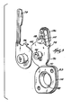
- FIG. 6 illustrates that the automatic choke apparatus 54a includes a mechanism 62a, and a thermally conductive assembly 66a.
- the mechanism 62a includes a linkage 74a that includes a stop lever 78a coupled to the thermally conductive assembly 66a via a lever linkage 144, a tab 82a coupled to the air vane 22a, and the choke linkage 30a.
- the thermally conductive assembly 66a includes a cover 86a coupled to the conductive element 90a.
- the conductive element 90a is coupled to the engine 10a and includes a chamber 148 that receives the bimetallic coil 118.
- the conductive element 90a includes a first aperture 94a that extends rearwardly from the chamber 148.
- a link arm 156 extends through the first aperture 94a and is coupled to the coil 118.
- the link arm 156 will be described in greater detail below.
- a coil aperture 128a in the cover 86a receives the coil tab 132 to secure the coil 118.
- the cover 86a also includes a link aperture 152 that receives a fastening member 160 (see FIG. 6 ), such as a screw or a bolt, to attach the cover 86a to the conductive element 90a.
- the conductive element 90a also includes a bridge 110a to connect the exhaust flange 88.
- the lever linkage 144 includes the link arm 156, which is coupled to the coil 118, a first lever link 164, a second lever link 168, and the stop lever 78a.
- the coil 118 expands or contracts, causing rotation of the link arm 156.
- the link arm 156 through the interaction of the first and second lever links 164, 168, actuates the stop lever 78a to interact with the tab 82a of the air vane 22a, holding the air vane 22a away from the fan 26.
- This interaction between the tab 82a and the stop lever 78a actuates the choke linkage 30a and opens the choke valve 18. If the engine 10a is started when the coil 118 senses that the predetermined temperature has been reached, the mechanism 62a will prevent the choke valve 18 from closing.
- FIGS. 9-12 illustrate another embodiment of the automatic choke apparatus of the present invention. Similar parts have been given the reference numeral "b" when appropriate.
- the automatic choke apparatus 54b includes the mechanism 62 described above with respect to FIGS. 1-4 , and a thermally conductive assembly 66b.
- the automatic choke apparatus 54b is operable with the air vane 22 described above with respect to FIG. 1 .
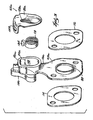
- the thermally conductive assembly 66b includes a thermally conductive cover 86b located adjacent the muffler 58 of the engine. As discussed above with respect to FIGS. 2 and 3 , the size, geometry, and material of the conductive cover 86b are chosen to optimize heat transfer through the cover 86b.
- the cover 86b includes an aperture to receive the coil tab 132b. Coupled to the cover 86b adjacent the muffler 58 is a retaining ring 176.
- the thermally conductive assembly 66b further includes a conductive element 90b that is coupled to the engine housing.
- the conductive element 90b includes a first aperture 94b that is configured to receive the mounting pin 98 coupled to the stop lever 78.
- the conductive element 90b also includes a first side projection 180, a second side projection 184 (best seen in FIG. 11 ) and a first forward projection 186.
- First and second retainer apertures 188, 192 are configured to receive the side projections 180, 184 when the elements of the thermally conductive assembly 66b are coupled together.
- the first forward projection 186 is configured to fit within the conductive cover 86b.
- the thermally conductive assembly 66b also includes a wave washer 196 that fits between the conductive element 90b and the cover 86b to provide a tight fit between the cover 86b and the conductive element 90b.
- the bimetallic coil 118b is coupled to the conductive element 90b within the cover 86b.
- the position of the cover 86b can be easily adjusted using an adjustment member, such as a thin blade wrench 200, to vary the air gap between the stop lever 78 and the tab 82 coupled to the air vane 22.
- an adjustment member such as a thin blade wrench 200
- the coil 118b is also adjusted through the interaction of the coil tab 132b with the cover 86b.
- FIGS. 14-21 illustrate the automatic choke apparatus 54b described above with respect to FIGS. 9-12 , operable with another air vane 22b according to the invention.
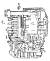
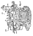
- FIGS. 14-17 , 20 , and 21 illustrate the engine 10b including a choke valve assembly 14b and the thermally conductive assembly 66b described above.
- the choke valve assembly 14b includes an offset choke valve 18b, best shown in FIGS. 17 , 20 , and 21 .
- the offset choke valve 18b moves momentarily before the air vane 22b moves, providing initial opening torque to the air vane 22b.
- FIGS. 14-17 illustrate the engine with the choke valve assembly 14b in the closed position
- FIGS. 20 and 21 illustrate the choke valve assembly 14b in the open position.
- the engine 10b includes a choke operating assembly 222.
- the choke operating assembly 222 includes the air vane 22b and the choke linkage 30b.
- the choke linkage 30b having a first choke arm 34b and a second choke arm 38b.
- the choke operating assembly 222 is connected to the choke valve 18 via a choke lever 50b.
- the air vane 22b, the first choke arm 34b, and the second choke arm 38b are integrally formed as a unitary body, such as by injection molding.
- the second choke arm 38b includes a hook-like protrusion 210 that is coupled to a biasing member that biases the choke valve 18 in the closed position.
- the biasing member is a spring 214, but it is understood that in other embodiments the biasing member could be any appropriate structure that acts to bias the choke valve 18 in the closed position.
- the air vane 22b also includes a tab 82b that can be engaged by the stop lever 78 of the mechanism 62.
- FIGS. 20 and 21 illustrate the choke valve assembly 14 in the open position. Similar to the operation described above with respect to FIGS. 1-4 , heat from the exhaust gases is conducted by the thermally conductive assembly 66b and transmitted to the coil 118b through thermal contact with the coil. The contraction or expansion of the coil 118b results in rotation of the stop lever 78. The stop lever 78 then interacts with the tab 82b to hold the air vane 22b away from the fan 26. This interaction overcomes the biasing force of the spring 214 to cause the choke lever 50b to rotate, opening the choke valve 18. With the choke valve 18 open, more air enters the combustion chamber such that the engine will not stumble or stall due to an overly rich fuel-air mixture.
- FIGS. 22-24 illustrate another embodiment of the automatic choke apparatus of the present invention. Similar parts have been given reference numeral "c" when appropriate.
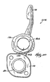
- FIGS. 22 and 23 illustrate a thermally conductive assembly 66c for use in an automatic choke apparatus 54c.
- the automatic choke apparatus 54c includes a mechanism 62c substantially similar to the mechanism 62 described above with respect to FIGS. 1-4 .
- the mechanism 62c includes a linkage that includes a stop lever 78c coupled to the thermally conductive assembly 66c, a tab 82c coupled to the air vane 22c, and a choke linkage 30c (see FIG. 24 ).
- the stop lever 78c includes a rigid portion 228, an aperture 230, and an L-shaped member 234.
- the L-shaped member 234 is movable with respect to the rigid portion 228 such that the thermally conductive assembly 66c is adjustable by moving the L-shaped member 234 over the rigid portion 228 (as shown in shadow in FIG. 22 ), thereby making the aperture 230 larger or smaller, depending on the direction of motion. Adjusting the stop lever 78c in this way varies the air gap between the stop lever 78c and the tab 82c coupled to the air vane 22c. This configuration of the stop lever 78c further simplifies the adjustment of the thermally conductive assembly 66c.
- the thermally conductive assembly 66c includes a cover 86c coupled to the conductive element 90c.
- a thermally responsive member such as the bimetallic coil 118 described above, is housed between the cover 86c and the conductive element 90c.
- the cover 86c includes two tabs 238 (only one is illustrated) that cooperate with a first portion 92c of the conductive element 90c to couple the cover 86c to the conductive element 90c.
- the first portion 92c of the conductive element 90c includes two apertures 242 (only one shown) for receiving the tabs 238.
- the cover 86c is secured to the conductive element 90c by bending the tabs 238 over the first portion 92c of the conductive element.
- the cover 86c is secured to the conductive element 90c without using a separate fastener.
- FIG. 24 illustrates the air vane 22c for use with the thermally conductive assembly 66c.
- the air vane 22c is similar to the air vane 22b discussed above with respect to FIGS. 16 , 18, and 19 , with the addition of a rib 246 to strengthen the first choke arm 34c, and a baffle 250 extending outwardly from the first choke arm 34c.
- the baffle 250 helps block air from flowing out of the engine to improve the cooling of the engine.
Landscapes
- Engineering & Computer Science (AREA)
- Chemical & Material Sciences (AREA)
- Combustion & Propulsion (AREA)
- Mechanical Engineering (AREA)
- General Engineering & Computer Science (AREA)
- Means For Warming Up And Starting Carburetors (AREA)
- Control Of Throttle Valves Provided In The Intake System Or In The Exhaust System (AREA)
Abstract
Claims (23)
- Moteur à combustion interne (10), comprenant :une soupape d'étranglement (18) ;un dispositif de commande d'étrangleur qui actionne la soupape d'étranglement (18) ;un assemblage thermoconducteur (66, 66a) qui est en contact direct avec les gaz d'échappement produits par le moteur ; un élément thermosensible (118) qui est en communication thermique avec l'ensemble thermoconducteur (66, 66a) de sorte que l'ensemble thermoconducteur (66, 66a) transfère de la chaleur depuis les gaz d'échappement à l'élément thermosensible (118) ; etun mécanisme (62) qui se déplace en réponse à l'élément thermosensible (118) pour amener la soupape d'étranglement (18) à rester dans une position au moins partiellement ouverte au cours de la mise en marche du moteur, lorsque l'élément thermosensible (118) détecte une température supérieure à une température prédéterminée, caractérisé en ce quel'ensemble thermoconducteur (66, 66a) comprend un élément thermoconducteur (90) comprenant une première partie (92, 92a, 92b), une seconde partie (93, 93a, 93b) et un pont (110, 110a) raccordant la première partie (92, 92a, 92b) à la seconde partie (93, 93a, 93b), dans lequel l'élément thermosensible (118) est couplé à la première partie (92, 92a, 92b) et dans lequel la seconde partie (93, 93a, 93b) comprend une bride d'échappement (88) qui entoure au moins en partie le trajet direct des gaz d'échappement et adaptée pour coopérer avec la sortie d'un collecteur d'échappement et/ou d'un silencieux (58) du moteur (10).
- Moteur selon la revendication 1, dans lequel l'élément thermosensible (118) comprend un bilame ou un moteur à cire.
- Moteur selon la revendication 1, dans lequel le dispositif d'étranglement comprend une aube (22) qui se déplace en fonction de la vitesse du moteur (10).
- Moteur selon la revendication 3, dans lequel le moteur (1) comprend un ventilateur (26) et dans lequel l'aube (22) se déplace en réponse au flux d'air produit par le ventilateur.
- Moteur (10) selon la revendication 1, dans lequel la soupape d'étranglement (18) est interconnectée au dispositif de commande d'étrangleur via un raccordement d'étranglement (30), le raccordement d'étranglement comprenant un levier d'étrangleur (50).
- Moteur (10) selon la revendication 5, dans lequel le raccordement d'étranglement (30) comprend un élément de sollicitation (42) et dans lequel la soupape d'étranglement (18) est sollicitée à sa fermeture par l'élément de sollicitation.
- Moteur (10) selon la revendication 5, dans lequel le raccordement d'étranglement (30) comprend un premier bras d'étranglement (34) et un second bras d'étranglement (38) et dans lequel le dispositif de commande d'étrangleur, le premier bras d'étranglement et le second bras d'étranglement constituent un corps unitaire d'un seul tenant qui agit directement sur la soupape d'étranglement (18).
- Moteur (10) selon la revendication 7, dans lequel la soupape d'étranglement (18) est sollicitée à sa fermeture par un élément de sollicitation (42) et dans lequel le second bras d'étranglement (38) comprend une saillie, de sorte que l'élément de sollicitation soit couplé à la saillie.
- Moteur (10) selon la revendication 1, dans lequel l'élément thermoconducteur (90a) comprend une chambre (148) et dans lequel l'élément thermosensible (118) est disposé dans la chambre.
- Moteur (10) selon la revendication 1, dans lequel aussi bien la première partie (92), la seconde partie (93) et le pont (110) ont une largeur et dans lequel la largeur du pont est moindre que la largeur de l'une ou l'autre des première et seconde parties.
- Moteur (10) selon la revendication 1, dans lequel l'ensemble thermoconducteur (66, 66a) comprend un couvercle (86).
- Moteur (10) selon la revendication 11, dans lequel le couvercle (86, 86a) est couplé en contact mécanique avec l'élément thermosensible (118).
- Moteur (10) selon la revendication 1, dans lequel l'élément thermosensible (118) a au moins l'un parmi un coefficient de dilatation thermique élevé ou un coefficient de contraction thermique élevé, de sorte que l'élément thermosensible se dilate ou se contracte en réponse à des changements de température.
- Moteur (10) selon la revendication 13, dans lequel l'élément thermosensible (118) comprend une bobine bilame (118).
- Moteur (10) selon la revendication 14, dans lequel la bobine bilame (118) a une configuration radiale.
- Moteur (10) selon la revendication 1, dans lequel la géométrie spécifique de l'ensemble thermoconducteur (66, 66a) est choisie afin de diriger le transfert de chaleur vers l'élément thermosensible (118).
- Moteur (10) selon la revendication 1, dans lequel le mécanisme (78) comprend un levier d'arrêt (78) couplé à l'élément thermosensible (118) de sorte que, lorsque l'élément thermosensible (118) détecte une température supérieure à la température prédéterminée, le levier d'arrêt interagisse avec le dispositif de commande d'étrangleur et que le dispositif de commande d'étrangleur interagisse avec un levier d'étrangleur (50) pour maintenir la soupape d'étranglement (18) au moins partiellement ouverte au cours de la mise en marche du moteur.
- Moteur (10) selon la revendication 1, dans lequel le mécanisme (62) comprend un raccordement (30) et dans lequel le raccordement comprend un levier d'arrêt (78), une languette (82) couplée au dispositif de commande d'étrangleur qui interagit avec le levier d'arrêt, un raccordement d'étranglement couplé au dispositif de commande d'étrangleur comprenant un levier d'étrangleur (50), le levier d'étrangleur étant adapté pour actionner la soupape d'étranglement (18).
- Moteur (10) selon la revendication 1, comprenant en outre un raccordement de levier couplé à l'ensemble thermoconducteur (66, 66a) et dans lequel le raccordement de levier comprend un bras de raccordement, un premier raccordement à levier et un seconde raccordement à levier.
- Procédé de commande d'un étranglement dans un moteur à combustion interne (10) utilisant la chaleur de l'échappement, le moteur à combustion interne ayant une soupape d'étranglement (18) qui peut être actionnée par un dispositif de commande d'étrangleur en réponse à la vitesse du moteur, un élément thermosensible (118) et un raccordement (30) entre l'élément thermosensible (118) et le dispositif de commande d'étrangleur, dans lequel l'élément thermosensible (118) est couplé à une première partie (92, 92a, 92b) d'un élément thermoconducteur (90) et dans lequel la première partie (92, 92a, 92b) est raccordée à une seconde partie (93, 93a, 93b) au moyen d'un pont (110, 110a), caractérisé en ce que
la seconde partie (92, 92a, 92b) de l'élément thermoconducteur (90), adaptée pour coopérer avec le collecteur d'échappement et/ou le silencieux, est configurée pour entourer au moins en partie les gaz d'échappement produits par le moteur et est placée en contact direct avec les gaz d'échappement ;
de la chaleur est transmise depuis les gaz d'échappement directement à la seconde partie (93, 93a) de l'élément thermoconducteur (90) via un matériau plein ;
de la chaleur est transmise de la seconde partie (93, 93a, 93b) de l'élément thermoconducteur (90) à travers le pont (110, 110a) à la première partie (92, 92a, 92b) et à un élément thermosensible (118) en contact thermique avec la première partie (92, 92a, 92b) de l'élément thermoconducteur (90) ; et
au cours de redémarrages du moteur, la fermeture complète de la soupape d'étranglement (18) est empêchée lorsque l'élément thermosensible (118) détecte que la température du moteur a atteint une température prédéterminée. - Procédé selon la revendication 20, dans lequel l'étape d'empêchement comprend la mise en oeuvre d'un mécanisme (62) qui restreint le mouvement du dispositif de commande d'étrangleur.
- Procédé selon la revendication 20, dans lequel la transmission de chaleur à l'élément thermosensible (118) provoque la dilatation ou la contraction de l'élément thermosensible et dans lequel la dilatation ou la contraction de l'élément thermosensible retient la soupape d'étranglement (18) dans une position au moins partiellement ouverte une fois que le moteur (10) atteint la température prédéterminée.
- Procédé selon la revendication 20, dans lequel l'élément thermosensible (118) est un bilame ou un moteur à cire.
Priority Applications (3)
| Application Number | Priority Date | Filing Date | Title |
|---|---|---|---|
| PL04778188T PL1649155T3 (pl) | 2003-07-30 | 2004-07-14 | Automat rozruchowy dla silnika |
| PL10178135T PL2261493T3 (pl) | 2003-07-30 | 2004-07-14 | Automat rozruchowy dla silnika |
| EP10178135A EP2261493B1 (fr) | 2003-07-30 | 2004-07-14 | Volet d'air automatique pour un moteur |
Applications Claiming Priority (3)
| Application Number | Priority Date | Filing Date | Title |
|---|---|---|---|
| US49121603P | 2003-07-30 | 2003-07-30 | |
| US10/784,542 US6990969B2 (en) | 2003-07-30 | 2004-02-23 | Automatic choke for an engine |
| PCT/US2004/022551 WO2005012715A2 (fr) | 2003-07-30 | 2004-07-14 | Volet d'air automatique pour moteur |
Related Child Applications (1)
| Application Number | Title | Priority Date | Filing Date |
|---|---|---|---|
| EP10178135.9 Division-Into | 2010-09-22 |
Publications (2)
| Publication Number | Publication Date |
|---|---|
| EP1649155A2 EP1649155A2 (fr) | 2006-04-26 |
| EP1649155B1 true EP1649155B1 (fr) | 2010-11-03 |
Family
ID=34107974
Family Applications (2)
| Application Number | Title | Priority Date | Filing Date |
|---|---|---|---|
| EP04778188A Expired - Lifetime EP1649155B1 (fr) | 2003-07-30 | 2004-07-14 | Volet d'air automatique pour moteur |
| EP10178135A Expired - Lifetime EP2261493B1 (fr) | 2003-07-30 | 2004-07-14 | Volet d'air automatique pour un moteur |
Family Applications After (1)
| Application Number | Title | Priority Date | Filing Date |
|---|---|---|---|
| EP10178135A Expired - Lifetime EP2261493B1 (fr) | 2003-07-30 | 2004-07-14 | Volet d'air automatique pour un moteur |
Country Status (9)
| Country | Link |
|---|---|
| US (1) | US6990969B2 (fr) |
| EP (2) | EP1649155B1 (fr) |
| AU (1) | AU2004260947B2 (fr) |
| BR (1) | BRPI0412346A (fr) |
| CA (1) | CA2532287C (fr) |
| DE (1) | DE602004029895D1 (fr) |
| PL (2) | PL2261493T3 (fr) |
| RU (1) | RU2309284C2 (fr) |
| WO (1) | WO2005012715A2 (fr) |
Families Citing this family (33)
| Publication number | Priority date | Publication date | Assignee | Title |
|---|---|---|---|---|
| TWI268309B (en) * | 2004-03-03 | 2006-12-11 | Honda Motor Co Ltd | Device for controlling choke valve of carburetor |
| TWI297372B (en) * | 2004-03-03 | 2008-06-01 | Honda Motor Co Ltd | Device for controlling choke valve of carburetor |
| EP1621754B1 (fr) * | 2004-07-26 | 2013-04-24 | Honda Motor Co., Ltd. | Dispositif de starter automatique pour carburateur |
| US20060043620A1 (en) * | 2004-08-24 | 2006-03-02 | David Roth | Automatic choke for an engine |
| US7144000B2 (en) * | 2004-08-24 | 2006-12-05 | Briggs & Stratton Corporation | Automatic choke for an engine |
| WO2007043916A1 (fr) * | 2005-10-07 | 2007-04-19 | Husqvarna Ab | Mecanisme d'enrichisseur de carburateur |
| US7464681B2 (en) * | 2006-02-28 | 2008-12-16 | Caterpillar Inc. | Engine and engine control method |
| US20080045589A1 (en) * | 2006-05-26 | 2008-02-21 | Susan Kelley | Drug Combinations with Substituted Diaryl Ureas for the Treatment of Cancer |
| EP2025909A3 (fr) * | 2007-08-13 | 2010-03-10 | Briggs and Stratton Corporation | Volet d'air automatique pour moteur |
| US8240639B2 (en) | 2007-12-06 | 2012-08-14 | Briggs & Stratton Corporation | Carburetor and automatic choke assembly for an engine |
| US8434444B2 (en) * | 2008-05-27 | 2013-05-07 | Briggs & Stratton Corporation | Engine with an automatic choke and method of operating an automatic choke for an engine |
| US8261712B2 (en) * | 2008-06-05 | 2012-09-11 | Kohler Co. | Automatic choke system |
| US7628387B1 (en) | 2008-07-03 | 2009-12-08 | Briggs And Stratton Corporation | Engine air/fuel mixing apparatus |
| US8448622B2 (en) * | 2009-08-04 | 2013-05-28 | Briggs And Stratton Corporation | Choke and priming system for an internal combustion engine |
| US8495995B2 (en) | 2010-06-23 | 2013-07-30 | Briggs And Stratton Corporation | Automatic choke for an engine |
| US9157407B2 (en) * | 2010-07-29 | 2015-10-13 | Mtd Products Inc | Starting system for internal combustion engine |
| JP5694725B2 (ja) * | 2010-09-30 | 2015-04-01 | 富士重工業株式会社 | エンジンのオートチョーク装置 |
| JP5318075B2 (ja) * | 2010-11-16 | 2013-10-16 | 富士重工業株式会社 | オートチョーク装置 |
| JP5687542B2 (ja) * | 2011-03-29 | 2015-03-18 | 富士重工業株式会社 | エンジンのオートチョーク装置 |
| JP5846852B2 (ja) * | 2011-10-26 | 2016-01-20 | 株式会社ミクニ | 気化器のチョーク機構 |
| US10215130B2 (en) * | 2012-02-10 | 2019-02-26 | Briggs & Stratton Corporation | Choke override for an engine |
| DE102012012799A1 (de) | 2012-06-28 | 2014-01-02 | Andreas Stihl Ag & Co. Kg | Arbeitsgerät mit einer Bremseinrichtung |
| DE102012012798B4 (de) | 2012-06-28 | 2014-11-13 | Andreas Stihl Ag & Co. Kg | Arbeitsgerät mit einer Bremseinrichtung |
| DE102012012801A1 (de) * | 2012-06-28 | 2014-01-02 | Andreas Stihl Ag & Co. Kg | Arbeitsgerät |
| US9429107B2 (en) | 2013-02-22 | 2016-08-30 | Briggs & Stratton Corporation | Solenoid autochoke for an engine |
| CN104884776B (zh) | 2013-08-15 | 2018-09-25 | 科勒公司 | 用于电子地控制内燃机的燃料空气比的系统和方法 |
| US10054081B2 (en) | 2014-10-17 | 2018-08-21 | Kohler Co. | Automatic starting system |
| US9945326B2 (en) | 2015-05-07 | 2018-04-17 | Briggs & Stratton Corporation | Automatic choking mechanism for internal combustion engines |
| US9932936B2 (en) | 2015-11-11 | 2018-04-03 | Briggs & Stratton Corporation | Carburetor choke removal mechanism for pressure washers |
| JP6976208B2 (ja) * | 2018-03-23 | 2021-12-08 | 川崎重工業株式会社 | 汎用エンジン |
| JP6942882B2 (ja) | 2018-03-30 | 2021-09-29 | 本田技研工業株式会社 | 気化器のオートチョーク装置 |
| WO2021014609A1 (fr) * | 2019-07-24 | 2021-01-28 | 本田技研工業株式会社 | Mécanisme d'ouverture/fermeture d'organe d'aspiration |
| USD1021704S1 (en) * | 2020-10-02 | 2024-04-09 | Bugatti International SA | Automobile body part—spider |
Family Cites Families (33)
| Publication number | Priority date | Publication date | Assignee | Title |
|---|---|---|---|---|
| US1996802A (en) | 1933-06-09 | 1935-04-09 | Briggs & Stratton Corp | Automatic choke control |
| US2086023A (en) | 1934-12-08 | 1937-07-06 | Briggs & Stratton Corp | Automatic carburetor choke control |
| US2139355A (en) * | 1936-03-17 | 1938-12-06 | Carter Carburetor Corp | Carburetor device |
| US2548334A (en) | 1947-03-17 | 1951-04-10 | Briggs & Stratton Corp | Automatic choke control for internal-combustion engines |
| US3194224A (en) | 1962-06-27 | 1965-07-13 | Briggs & Stratton Corp | Air cooled internal combustion engine |
| US3161186A (en) | 1963-04-05 | 1964-12-15 | Briggs & Stratton Corp | Method and means for improving acceleration of small engines |
| US3319943A (en) | 1965-04-19 | 1967-05-16 | Bendix Corp | Carburetor choking device |
| US3305223A (en) | 1965-09-30 | 1967-02-21 | Briggs & Stratton Corp | Carburetor with improved choke valve control |
| US3315949A (en) | 1965-10-22 | 1967-04-25 | Bendix Corp | Automatic choke |
| US3834677A (en) * | 1970-09-02 | 1974-09-10 | Hitachi Ltd | Automatic choke control |
| US3789815A (en) | 1971-02-17 | 1974-02-05 | Carter C | Temperature responsive control device |
| US4050427A (en) | 1971-11-02 | 1977-09-27 | Ford Motor Company | Carburetor automatic choke construction |
| US3828745A (en) * | 1972-12-26 | 1974-08-13 | Ford Motor Co | Automatic choke control for engines |
| US3898967A (en) | 1973-06-04 | 1975-08-12 | Gte Sylvania Inc | Automatic choke assembly |
| US3863614A (en) | 1973-11-19 | 1975-02-04 | Briggs & Stratton Corp | Thermostatic automatic choke control for small engines |
| US3998967A (en) * | 1973-12-12 | 1976-12-21 | Stauffer Chemical Company | Method of inhibiting the growth of bacteria and fungi with higher aliphatic amine salts of nitrilotriacetic acid |
| US3886241A (en) | 1974-03-06 | 1975-05-27 | Ford Motor Co | Carburetor cold enrichment control |
| US3957026A (en) | 1974-07-24 | 1976-05-18 | Winkley Jerry H | Cold starting enrichment device |
| US4023550A (en) | 1974-08-27 | 1977-05-17 | Briggs & Stratton Corporation | Engine with overspeed prevention |
| US4031872A (en) | 1974-10-21 | 1977-06-28 | Briggs & Stratton Corporation | Thermostatic automatic choke control for small engines |
| US3970059A (en) | 1975-04-30 | 1976-07-20 | Pisar Robert J | Engine speed control for an internal combustion engine adapted for operation with L.P. gas |
| US4068636A (en) | 1975-10-29 | 1978-01-17 | Briggs & Stratton Corporation | Thermostatic device for automatic choke control |
| US4221202A (en) | 1978-06-15 | 1980-09-09 | Outboard Marine Corporation | Air vane carburetor with adjustable speed |
| US4297980A (en) * | 1980-04-10 | 1981-11-03 | Ford Motor Company | Motor vehicle carburetor choke mechanism |
| US4368163A (en) | 1981-07-01 | 1983-01-11 | Covey Jr Ray M | Apparatus for vaporizing fuel for engine in conjunction with carburetor |
| IT1157490B (it) * | 1982-12-20 | 1987-02-11 | Weber Spa | Carburatore per motori a combustione interna provvisto di organi ad azione elettronica atti a mantenere costante il minimo regime del motore ed a controllare la posizione della farfalla di avviamento durante la messa in efficienza del motore |
| JPH0759896B2 (ja) | 1986-07-29 | 1995-06-28 | 三信工業株式会社 | 船舶推進機の排気浄化装置 |
| US5069180A (en) | 1990-10-19 | 1991-12-03 | Onan Corporation | Automatic choke apparatus and method |
| JPH07158510A (ja) | 1993-12-03 | 1995-06-20 | Kubota Corp | オートチョーク付き火花点火式エンジン |
| US5511519A (en) | 1994-07-05 | 1996-04-30 | Homelite, Inc. | Temperature adjusting automatic choke system |
| US5503125A (en) | 1995-06-26 | 1996-04-02 | Briggs & Stratton Corporation | Air vane governor with improved droop characteristics |
| US6012420A (en) | 1997-12-30 | 2000-01-11 | Briggs & Stratton Corporation | Automatic air inlet control system for an engine |
| US6722638B2 (en) | 2001-12-27 | 2004-04-20 | Honda Giken Kogyo Kabushiki Kaisha | Control system for choke valve of carburetor |
-
2004
- 2004-02-23 US US10/784,542 patent/US6990969B2/en not_active Expired - Lifetime
- 2004-07-14 PL PL10178135T patent/PL2261493T3/pl unknown
- 2004-07-14 AU AU2004260947A patent/AU2004260947B2/en not_active Ceased
- 2004-07-14 EP EP04778188A patent/EP1649155B1/fr not_active Expired - Lifetime
- 2004-07-14 EP EP10178135A patent/EP2261493B1/fr not_active Expired - Lifetime
- 2004-07-14 BR BRPI0412346-8A patent/BRPI0412346A/pt not_active IP Right Cessation
- 2004-07-14 CA CA002532287A patent/CA2532287C/fr not_active Expired - Fee Related
- 2004-07-14 PL PL04778188T patent/PL1649155T3/pl unknown
- 2004-07-14 RU RU2006106277/06A patent/RU2309284C2/ru not_active IP Right Cessation
- 2004-07-14 DE DE602004029895T patent/DE602004029895D1/de not_active Expired - Lifetime
- 2004-07-14 WO PCT/US2004/022551 patent/WO2005012715A2/fr not_active Ceased
Also Published As
| Publication number | Publication date |
|---|---|
| AU2004260947A1 (en) | 2005-02-10 |
| RU2309284C2 (ru) | 2007-10-27 |
| AU2004260947B2 (en) | 2008-02-14 |
| EP1649155A2 (fr) | 2006-04-26 |
| PL2261493T3 (pl) | 2013-05-31 |
| DE602004029895D1 (de) | 2010-12-16 |
| CA2532287A1 (fr) | 2005-02-10 |
| WO2005012715A3 (fr) | 2005-04-07 |
| EP2261493B1 (fr) | 2013-01-23 |
| US6990969B2 (en) | 2006-01-31 |
| RU2006106277A (ru) | 2006-07-10 |
| PL1649155T3 (pl) | 2011-04-29 |
| EP2261493A1 (fr) | 2010-12-15 |
| WO2005012715A2 (fr) | 2005-02-10 |
| CA2532287C (fr) | 2008-09-09 |
| BRPI0412346A (pt) | 2006-09-05 |
| US20050022798A1 (en) | 2005-02-03 |
Similar Documents
| Publication | Publication Date | Title |
|---|---|---|
| CA2532287C (fr) | Volet d'air automatique pour moteur | |
| CN100449136C (zh) | 发动机的化油器自动控制装置 | |
| US8746207B2 (en) | Automatic choke for an engine | |
| US8146558B2 (en) | Automatic choke for an engine | |
| US7246794B2 (en) | Carburetor throttle valve control system | |
| CN100406710C (zh) | 用于发动机的自动阻气门及其操作方法 | |
| US7144000B2 (en) | Automatic choke for an engine | |
| EP1621754B1 (fr) | Dispositif de starter automatique pour carburateur | |
| US10215130B2 (en) | Choke override for an engine | |
| CN100387820C (zh) | 用于发动机的自动阻风门 | |
| JP5694725B2 (ja) | エンジンのオートチョーク装置 | |
| JP4970298B2 (ja) | 気化器の制御装置 | |
| JP4970297B2 (ja) | 気化器の制御装置 | |
| JP4199171B2 (ja) | 気化器のオートチョーク装置 | |
| JPH0315787Y2 (fr) | ||
| JPH09280113A (ja) | オートチョーク弁付気化器 | |
| JP2006037805A (ja) | 気化器のオートチョーク装置 | |
| JPH08177633A (ja) | 気化器の自動チョーク装置 | |
| JPS62261654A (ja) | 自動チヨ−ク装置の二段完爆機構 |
Legal Events
| Date | Code | Title | Description |
|---|---|---|---|
| PUAI | Public reference made under article 153(3) epc to a published international application that has entered the european phase |
Free format text: ORIGINAL CODE: 0009012 |
|
| 17P | Request for examination filed |
Effective date: 20060104 |
|
| AK | Designated contracting states |
Kind code of ref document: A2 Designated state(s): CZ DE FR GB IT PL |
|
| DAX | Request for extension of the european patent (deleted) | ||
| RBV | Designated contracting states (corrected) |
Designated state(s): CZ DE FR GB IT PL |
|
| 17Q | First examination report despatched |
Effective date: 20070716 |
|
| GRAP | Despatch of communication of intention to grant a patent |
Free format text: ORIGINAL CODE: EPIDOSNIGR1 |
|
| GRAS | Grant fee paid |
Free format text: ORIGINAL CODE: EPIDOSNIGR3 |
|
| GRAA | (expected) grant |
Free format text: ORIGINAL CODE: 0009210 |
|
| AK | Designated contracting states |
Kind code of ref document: B1 Designated state(s): CZ DE FR GB IT PL |
|
| REG | Reference to a national code |
Ref country code: GB Ref legal event code: FG4D |
|
| REF | Corresponds to: |
Ref document number: 602004029895 Country of ref document: DE Date of ref document: 20101216 Kind code of ref document: P |
|
| REG | Reference to a national code |
Ref country code: PL Ref legal event code: T3 |
|
| PLBE | No opposition filed within time limit |
Free format text: ORIGINAL CODE: 0009261 |
|
| STAA | Information on the status of an ep patent application or granted ep patent |
Free format text: STATUS: NO OPPOSITION FILED WITHIN TIME LIMIT |
|
| 26N | No opposition filed |
Effective date: 20110804 |
|
| REG | Reference to a national code |
Ref country code: DE Ref legal event code: R097 Ref document number: 602004029895 Country of ref document: DE Effective date: 20110804 |
|
| PGFP | Annual fee paid to national office [announced via postgrant information from national office to epo] |
Ref country code: IT Payment date: 20120713 Year of fee payment: 9 |
|
| PGFP | Annual fee paid to national office [announced via postgrant information from national office to epo] |
Ref country code: CZ Payment date: 20130710 Year of fee payment: 10 |
|
| PG25 | Lapsed in a contracting state [announced via postgrant information from national office to epo] |
Ref country code: IT Free format text: LAPSE BECAUSE OF NON-PAYMENT OF DUE FEES Effective date: 20130714 |
|
| PGFP | Annual fee paid to national office [announced via postgrant information from national office to epo] |
Ref country code: PL Payment date: 20140506 Year of fee payment: 11 |
|
| PG25 | Lapsed in a contracting state [announced via postgrant information from national office to epo] |
Ref country code: CZ Free format text: LAPSE BECAUSE OF NON-PAYMENT OF DUE FEES Effective date: 20140714 |
|
| REG | Reference to a national code |
Ref country code: FR Ref legal event code: PLFP Year of fee payment: 13 |
|
| PG25 | Lapsed in a contracting state [announced via postgrant information from national office to epo] |
Ref country code: PL Free format text: LAPSE BECAUSE OF NON-PAYMENT OF DUE FEES Effective date: 20150714 |
|
| REG | Reference to a national code |
Ref country code: FR Ref legal event code: PLFP Year of fee payment: 14 |
|
| REG | Reference to a national code |
Ref country code: FR Ref legal event code: PLFP Year of fee payment: 15 |
|
| PGFP | Annual fee paid to national office [announced via postgrant information from national office to epo] |
Ref country code: FR Payment date: 20180612 Year of fee payment: 15 |
|
| PGFP | Annual fee paid to national office [announced via postgrant information from national office to epo] |
Ref country code: DE Payment date: 20180703 Year of fee payment: 15 |
|
| PGFP | Annual fee paid to national office [announced via postgrant information from national office to epo] |
Ref country code: GB Payment date: 20180711 Year of fee payment: 15 |
|
| REG | Reference to a national code |
Ref country code: DE Ref legal event code: R119 Ref document number: 602004029895 Country of ref document: DE |
|
| GBPC | Gb: european patent ceased through non-payment of renewal fee |
Effective date: 20190714 |
|
| PG25 | Lapsed in a contracting state [announced via postgrant information from national office to epo] |
Ref country code: DE Free format text: LAPSE BECAUSE OF NON-PAYMENT OF DUE FEES Effective date: 20200201 Ref country code: GB Free format text: LAPSE BECAUSE OF NON-PAYMENT OF DUE FEES Effective date: 20190714 |
|
| PG25 | Lapsed in a contracting state [announced via postgrant information from national office to epo] |
Ref country code: FR Free format text: LAPSE BECAUSE OF NON-PAYMENT OF DUE FEES Effective date: 20190731 |