EP1649912A2 - Dispositif de séparation de constituants indésirables de liquides et dispositif de nettoyage - Google Patents
Dispositif de séparation de constituants indésirables de liquides et dispositif de nettoyage Download PDFInfo
- Publication number
- EP1649912A2 EP1649912A2 EP05016033A EP05016033A EP1649912A2 EP 1649912 A2 EP1649912 A2 EP 1649912A2 EP 05016033 A EP05016033 A EP 05016033A EP 05016033 A EP05016033 A EP 05016033A EP 1649912 A2 EP1649912 A2 EP 1649912A2
- Authority
- EP
- European Patent Office
- Prior art keywords
- plates
- cleaning
- carrier
- separating
- receiving unit
- Prior art date
- Legal status (The legal status is an assumption and is not a legal conclusion. Google has not performed a legal analysis and makes no representation as to the accuracy of the status listed.)
- Withdrawn
Links
- 239000007788 liquid Substances 0.000 title claims abstract description 15
- 238000004140 cleaning Methods 0.000 title claims description 38
- 239000000203 mixture Substances 0.000 claims abstract description 5
- 238000003860 storage Methods 0.000 claims description 10
- 238000000151 deposition Methods 0.000 claims description 4
- 239000012535 impurity Substances 0.000 abstract description 5
- 238000000926 separation method Methods 0.000 description 32
- XLYOFNOQVPJJNP-UHFFFAOYSA-N water Substances O XLYOFNOQVPJJNP-UHFFFAOYSA-N 0.000 description 5
- 239000000356 contaminant Substances 0.000 description 2
- 230000005484 gravity Effects 0.000 description 2
- 238000000034 method Methods 0.000 description 2
- 239000002245 particle Substances 0.000 description 2
- 238000005192 partition Methods 0.000 description 2
- 239000007787 solid Substances 0.000 description 2
- 238000010276 construction Methods 0.000 description 1
- 238000011109 contamination Methods 0.000 description 1
- 230000008021 deposition Effects 0.000 description 1
- 238000001914 filtration Methods 0.000 description 1
- 239000006260 foam Substances 0.000 description 1
- 238000005457 optimization Methods 0.000 description 1
- 239000011148 porous material Substances 0.000 description 1
- 238000001228 spectrum Methods 0.000 description 1
- 239000000126 substance Substances 0.000 description 1
Images

Classifications
-
- B—PERFORMING OPERATIONS; TRANSPORTING
- B01—PHYSICAL OR CHEMICAL PROCESSES OR APPARATUS IN GENERAL
- B01D—SEPARATION
- B01D25/00—Filters formed by clamping together several filtering elements or parts of such elements
-
- B—PERFORMING OPERATIONS; TRANSPORTING
- B01—PHYSICAL OR CHEMICAL PROCESSES OR APPARATUS IN GENERAL
- B01D—SEPARATION
- B01D29/00—Filters with filtering elements stationary during filtration, e.g. pressure or suction filters, not covered by groups B01D24/00 - B01D27/00; Filtering elements therefor
- B01D29/01—Filters with filtering elements stationary during filtration, e.g. pressure or suction filters, not covered by groups B01D24/00 - B01D27/00; Filtering elements therefor with flat filtering elements
- B01D29/05—Filters with filtering elements stationary during filtration, e.g. pressure or suction filters, not covered by groups B01D24/00 - B01D27/00; Filtering elements therefor with flat filtering elements supported
- B01D29/055—Filters with filtering elements stationary during filtration, e.g. pressure or suction filters, not covered by groups B01D24/00 - B01D27/00; Filtering elements therefor with flat filtering elements supported ring shaped
-
- B—PERFORMING OPERATIONS; TRANSPORTING
- B01—PHYSICAL OR CHEMICAL PROCESSES OR APPARATUS IN GENERAL
- B01D—SEPARATION
- B01D17/00—Separation of liquids, not provided for elsewhere, e.g. by thermal diffusion
- B01D17/02—Separation of non-miscible liquids
-
- B—PERFORMING OPERATIONS; TRANSPORTING
- B01—PHYSICAL OR CHEMICAL PROCESSES OR APPARATUS IN GENERAL
- B01D—SEPARATION
- B01D17/00—Separation of liquids, not provided for elsewhere, e.g. by thermal diffusion
- B01D17/02—Separation of non-miscible liquids
- B01D17/0208—Separation of non-miscible liquids by sedimentation
- B01D17/0211—Separation of non-miscible liquids by sedimentation with baffles
-
- B—PERFORMING OPERATIONS; TRANSPORTING
- B01—PHYSICAL OR CHEMICAL PROCESSES OR APPARATUS IN GENERAL
- B01D—SEPARATION
- B01D17/00—Separation of liquids, not provided for elsewhere, e.g. by thermal diffusion
- B01D17/08—Thickening liquid suspensions by filtration
- B01D17/10—Thickening liquid suspensions by filtration with stationary filtering elements
-
- B—PERFORMING OPERATIONS; TRANSPORTING
- B01—PHYSICAL OR CHEMICAL PROCESSES OR APPARATUS IN GENERAL
- B01D—SEPARATION
- B01D25/00—Filters formed by clamping together several filtering elements or parts of such elements
- B01D25/28—Leaching or washing filter cakes in the filter handling the filter cake for purposes other than regenerating
-
- B—PERFORMING OPERATIONS; TRANSPORTING
- B01—PHYSICAL OR CHEMICAL PROCESSES OR APPARATUS IN GENERAL
- B01D—SEPARATION
- B01D2201/00—Details relating to filtering apparatus
- B01D2201/18—Filters characterised by the openings or pores
- B01D2201/188—Multiple filtering elements having filtering areas of different size
Definitions
- the invention relates to a device for separating admixtures from liquids, for use in a separation vessel for separating admixtures from a mixed-liquid mixture having a plate-like configuration.
- the invention further relates to a cleaning device for cleaning plate-shaped separating elements, which are provided in the region of separators for separating admixtures from a mixed-liquid mixture.
- Such separation devices are used for the separation of liquids or solids from a carrier liquid.
- so-called oil separators are constructed in two stages and separation of the oil takes place both by utilizing gravity due to different specific weights of the substances to be separated and by using separators which facilitate combining small and smallest contaminant particles into larger particles which is easier than very small parts have to be deposited.
- the separating elements serve to bring together finely divided emulsified oil droplets to larger drops of oil that rise in the water.
- the separators filter-like and retains finely divided solids that do not settle readily due to the gravitational effect.
- a plate-shaped deposition element arranged transversely to the flow direction is usually positioned, which is provided with fine through-channels or formed from a permeable foam.
- This separator provides the functions of filtering out finely divided contaminants as well as bringing together small droplets of oil.
- the duration of the respective use and cleaning cycles depends on the actual use conditions and in particular on the amount of the deposited impurities.
- Object of the present invention is to construct a device of the aforementioned type such that a high functionality is ensured at the same time easy handling.
- the plate-like configuration is formed by at least two successive plates and that the plates are supported by a rod-like carrier.
- Another object of the present invention is to construct a cleaning device of the initially mentioned type such that the performance of cleaning operations is facilitated.
- This object is achieved in that a three-part structure of a trough-shaped receiving unit, a cleaning unit and a lid-like storage unit is present.
- the plate-like design of the separating element with a common rod-like support a high technical effectiveness and easy handling is supported on the one hand.
- the separating element can be inserted into the respective oil separator and also removed therefrom.
- handling by means of lifting devices, for example with small cranes, is supported.
- the three-part design of the cleaning device allows for a stowage of the cleaning unit in an unused state compact and with a small footprint, in addition, contamination of an environment of the oil separator at a removal of the separating element from the oil separator are largely avoided.
- At least one of the plates has a macroporous structure.
- a compact arrangement is assisted in that the plates are formed as substantially circular discs.
- Handling by means of lifting devices is facilitated by the fact that the carrier is arranged centrally in the region of the plates.
- the carrier is tubular.
- Handling of the separating element using lifting devices is assisted in that the carrier is provided with at least one handling opening.
- the plates are supported by at least one retaining plate which is fixed to the carrier.
- a particularly compact embodiment of the cleaning device is assisted in that a side wall of the cover-shaped storage unit has a larger inner diameter than an outer diameter of a side wall of the trough-shaped receiving unit.
- a further improvement of the compact design can be achieved in that a cleaning unit arranged in the receiving unit can be covered by the cover-shaped storage unit.
- a high handling security is supported by the fact that the receiving unit is formed on a lid of the separator arranged anordbar.
- a preferred application is that the separation tank is designed for the separation of oil from water.
- Fig. 1 shows a schematic and partially sectioned side view of a device for the separation of admixtures from liquids, in particular for the separation of oil from water.
- the device has a first separation stage (1) and a second separation stage (2).
- the separation stages (1, 2) are supported by a common base (3).
- the first separation stage (1) has an upper separation chamber (4) and a lower separation chamber (5) which are delimited from one another by a sieve-like subdivision (6).
- a separator (8) is arranged in the lower separation chamber (5), which is typically formed from a foamy or porous material.
- a main flow direction (9) in the first separation stage (1) is oriented in the vertical direction from top to bottom.
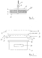
- FIG. 2 shows a separating element (21) with a plate-like construction which can be used as a separator (8) in the region of the first separating stage (1).
- the separating element (21) consists in the embodiment shown in Fig. 2 of three superimposed plates (22) which are supported by a rod-like support (23).
- the plates (22) are formed substantially as circular discs with a central recess. In the central recess of the carrier (23) is inserted.
- the carrier (23) may be tubular and is provided with at least one handling opening (24).
- two handling openings (24) are used to facilitate connection to a lifting device such as a crane.
- the plates (22) have a macroporous structure.
- the thickness of the plates (22) is preferably chosen to be different relative to each other and adapted to the particular application requirements.
- the plates (22) between two holding plates (25, 26) are inserted, which have a perforated structure.
- it is intended to rigidly connect at least the vertically lower holding plate (25) with the carrier (23).
- the plates (22) can thereby be loosely pushed onto the carrier (23) and thus require only a relatively low mechanical intrinsic stability.
- Fig. 3 shows a cleaning device (27) for the separator (8) and the separating element (21).
- the cleaning device is formed in three parts and consists of a trough-shaped receiving unit (28), a cleaning unit (29) and a lid-like tray (30).
- the cleaning unit (29) has an outer diameter such that it can be received by the receiving unit (28) in an unused state.
- a side wall (31) of the receiving unit (28) has an inner diameter which is larger than an outer diameter of a side wall (32) of the storage unit (30).
- the cover-like storage unit (30) can thereby be placed on the receiving unit (28).
- the receiving unit (28) is also provided in the region of an underside of a bottom (33) with a skirting web (34) whose inner diameter is formed adapted to an outer diameter of a lid (35) of the first separation stage (1). As a result, the receiving unit (28) can be placed mechanically stably on the cover (35).
- the cleaning device (27) In an unused state above the lid (35).
- the cleaning unit (29) is placed in the receiving unit (28) and a cover is effected by means of the cover-shaped storage unit (30).
- the cleaning device (27) is placed next to the first separating step (1) and the depositing unit (30) is removed and positioned in the area of a cleaning station. Subsequently, the cleaning unit (29) is removed from the receiving unit (28) and also positioned in the area of the cleaning station.
- the lid (35) is removed from the first separating stage (1) and the separating element (21) is removed from the first separating stage (1). Due to dripping impurities from the separating element (21) this first remains in the vertical direction above the first separation stage (1) positioned.
- the receiving unit (28) is placed on the first separation stage (1) and the contaminated separating element (21) is placed in the receiving unit (28). The receiving unit (28) is then transported together with the separating element (21) to the cleaning station and the separating element (21) is here converted into the cleaning unit (29). After completion of the cleaning process, the cleaned separating element (21) is placed on the storage unit (30).
- the separating element (21) is transported from the depositing unit (30) to the first separating stage (1) and inserted again into the first separating stage (1). After placing the lid (35), the operability is restored. After an optional cleaning of the cleaning device (27), these can also be reassembled and positioned at their storage location.
Landscapes
- Chemical & Material Sciences (AREA)
- Chemical Kinetics & Catalysis (AREA)
- Physics & Mathematics (AREA)
- Thermal Sciences (AREA)
- Cleaning By Liquid Or Steam (AREA)
- Cleaning In General (AREA)
- Filtration Of Liquid (AREA)
- Removal Of Floating Material (AREA)
Applications Claiming Priority (1)
| Application Number | Priority Date | Filing Date | Title |
|---|---|---|---|
| DE102004050741A DE102004050741A1 (de) | 2004-10-19 | 2004-10-19 | Vorrichtung zum Abscheiden von Beimengungen von Flüssigkeiten sowie Reinigungsvorrichtung |
Publications (2)
| Publication Number | Publication Date |
|---|---|
| EP1649912A2 true EP1649912A2 (fr) | 2006-04-26 |
| EP1649912A3 EP1649912A3 (fr) | 2006-06-07 |
Family
ID=35559288
Family Applications (1)
| Application Number | Title | Priority Date | Filing Date |
|---|---|---|---|
| EP05016033A Withdrawn EP1649912A3 (fr) | 2004-10-19 | 2005-07-23 | Dispositif de séparation de constituants indésirables de liquides et dispositif de nettoyage |
Country Status (6)
| Country | Link |
|---|---|
| US (1) | US20060081523A1 (fr) |
| EP (1) | EP1649912A3 (fr) |
| JP (1) | JP2006116530A (fr) |
| KR (1) | KR20060053277A (fr) |
| CN (1) | CN1768894A (fr) |
| DE (2) | DE102004050741A1 (fr) |
Families Citing this family (2)
| Publication number | Priority date | Publication date | Assignee | Title |
|---|---|---|---|---|
| CN102389676A (zh) * | 2011-10-13 | 2012-03-28 | 南车戚墅堰机车有限公司 | 板网滤清器组安装装置 |
| CN114378041A (zh) * | 2022-02-11 | 2022-04-22 | 陈惠玲 | 新型粉状物料和浆料的洗涤设备及洗涤方法 |
Citations (2)
| Publication number | Priority date | Publication date | Assignee | Title |
|---|---|---|---|---|
| FR1590931A (fr) | 1967-11-11 | 1970-04-20 | ||
| EP1275427A2 (fr) | 2001-07-11 | 2003-01-15 | Water Creations, Inc. | Filtre à plusieurs étages |
Family Cites Families (18)
| Publication number | Priority date | Publication date | Assignee | Title |
|---|---|---|---|---|
| US2705563A (en) * | 1952-11-12 | 1955-04-05 | Albert E Ide | Oil filter cartridge |
| DE1243645B (de) * | 1961-05-11 | 1967-07-06 | Shell Res Ltd | Abscheider zum Zerlegen eines eine relativ geringe OElmenge enthaltenden OEl-Wasser-Gemisches in seine Bestandteile |
| US3666107A (en) * | 1970-09-17 | 1972-05-30 | Food Research & Equipment Co | Filter unit |
| US3847821A (en) * | 1973-10-19 | 1974-11-12 | Minnesota Mining & Mfg | Separator for removing a dispersed liquid phase from a continuous liquid phase |
| DE2640803C2 (de) * | 1975-09-18 | 1982-03-11 | Thune-Eureka A/S, Tranby | Lamellenseparator zur Sedimentierung |
| US4042512A (en) * | 1976-10-27 | 1977-08-16 | Mccarthy Patrick M | Oil water separator |
| DE8600873U1 (de) * | 1986-01-16 | 1986-02-27 | B. Braun Melsungen Ag, 3508 Melsungen | Desinfektionsvorrichtung |
| US4792397A (en) * | 1987-06-09 | 1988-12-20 | Harvard Corporation | Filter apparatus with sealing collector and flow control element |
| DE3824295A1 (de) * | 1988-07-18 | 1990-01-25 | Preussag Ag Bauwesen | Klaervorrichtung |
| CH687023A5 (de) * | 1991-07-22 | 1996-08-30 | Heinz Wartenweiler | Anlage zur Reinigung von kontaminiertem Wasser. |
| DE4208506C2 (de) * | 1992-03-17 | 1996-08-08 | Hellmers Herm J Gmbh | Entsorgungsvorrichtung und Verfahren zum Abscheiden von Öl aus Schmutzwasser |
| DE4428625C2 (de) * | 1994-08-12 | 1999-03-25 | Munters Euroform Gmbh Carl | Anlage zur Abtrennung von Feststoffen aus fließfähigen Medien mit Spüleinrichtung |
| DE19705814C2 (de) * | 1997-02-15 | 1998-12-10 | Buderus Guss Gmbh | Leichtflüssigkeitsabscheider |
| US5928524A (en) * | 1997-03-31 | 1999-07-27 | Hoover Containment, Inc. | Oil-water separator |
| SE509656C2 (sv) * | 1997-04-15 | 1999-02-22 | Sweden Recycling Ab | Anordning för avskiljning av partiklar ur en vätska |
| GB2350571B (en) * | 1999-06-05 | 2002-12-18 | John Andrew Timmins | Separating apparatus and method of separating |
| JP2004050145A (ja) * | 2002-07-24 | 2004-02-19 | Taiko Kikai Industries Co Ltd | 微細な浮遊物質を含むビルジ用油水分離装置 |
| ITMI20031998A1 (it) * | 2003-10-16 | 2005-04-17 | Rosauto Srl | Vasca di lavaggio in particolare per freni di veicoli industriali e simili |
-
2004
- 2004-10-19 DE DE102004050741A patent/DE102004050741A1/de not_active Withdrawn
-
2005
- 2005-07-23 DE DE202005021393U patent/DE202005021393U1/de not_active Expired - Lifetime
- 2005-07-23 EP EP05016033A patent/EP1649912A3/fr not_active Withdrawn
- 2005-09-20 JP JP2005272200A patent/JP2006116530A/ja active Pending
- 2005-10-14 KR KR1020050096807A patent/KR20060053277A/ko not_active Withdrawn
- 2005-10-19 CN CNA2005101141243A patent/CN1768894A/zh active Pending
- 2005-10-19 US US11/254,116 patent/US20060081523A1/en not_active Abandoned
Patent Citations (2)
| Publication number | Priority date | Publication date | Assignee | Title |
|---|---|---|---|---|
| FR1590931A (fr) | 1967-11-11 | 1970-04-20 | ||
| EP1275427A2 (fr) | 2001-07-11 | 2003-01-15 | Water Creations, Inc. | Filtre à plusieurs étages |
Also Published As
| Publication number | Publication date |
|---|---|
| US20060081523A1 (en) | 2006-04-20 |
| JP2006116530A (ja) | 2006-05-11 |
| DE102004050741A1 (de) | 2006-04-20 |
| EP1649912A3 (fr) | 2006-06-07 |
| DE202005021393U1 (de) | 2007-11-15 |
| CN1768894A (zh) | 2006-05-10 |
| KR20060053277A (ko) | 2006-05-19 |
Similar Documents
| Publication | Publication Date | Title |
|---|---|---|
| EP0248429B1 (fr) | Procédé d'extraction de composés organiques de l'eau | |
| DE1645762C3 (de) | Vorrichtung zum Abscheiden von flüssigen Erdölprodukten aus einem Erdölprodukt-Wasser-Gemisch | |
| DE102017003577A1 (de) | Vorrichtung zum Behandeln von Fluid | |
| EP2313639A1 (fr) | Filtre à carburant | |
| DE4200379A1 (de) | Geraet zum abscheiden von oel aus einem oel/wasser-gemisch | |
| EP0561170B1 (fr) | Dispositif d'enlèvement pour la séparation de l'huile dans l'eau usée | |
| DE1619836B1 (de) | Vorrichtung zum Scheiden von Flüssigkeits-Gas-Gemischen | |
| WO2019224033A1 (fr) | Dispositif de séparation de phases | |
| DE60217014T2 (de) | Vorrichtung und Verfahren zum Sedimentieren feiner Feststoffpartikel aus einer kontinuierlich strömenden Suspension | |
| EP1649912A2 (fr) | Dispositif de séparation de constituants indésirables de liquides et dispositif de nettoyage | |
| DD275856B5 (de) | Koaleszenzabscheider | |
| DE4400612C2 (de) | Abscheideranlage | |
| EP2218688B1 (fr) | Procédé et dispositif de nettoyage anaérobie d'eau usée | |
| AT398752B (de) | Abscheider für leichtflüssigkeiten | |
| DE9105524U1 (de) | Abscheideranlage | |
| EP1645317A1 (fr) | Dispositif pour séparer des impuretés des liquides | |
| EP3211205A1 (fr) | Module de nettoyage, élément de filtre et système de filtre | |
| DE4336787C1 (de) | Modul für biologische Abwasserreinigung | |
| EP0817666A1 (fr) | Procede de separation solide-liquide et/ou de rupture d'emulsion | |
| DE29914781U1 (de) | Kleinkläranlage | |
| DE3341281A1 (de) | Fluessigkeitsfilter | |
| AT398959B (de) | Anlage zum abscheiden von leichtflüssigkeiten, insb. mineralölen | |
| DE2808657C3 (de) | Vorrichtung zum Trennen zweier miteinander nicht mischbarer Flüssigkeiten unterschiedlicher Dichte, vorzugsweise von Wasser-Öl-Gemischen | |
| DE102009012190B4 (de) | Vorrichtung zum Abscheiden von Beimengungen von Flüssigkeiten | |
| EP1877155A1 (fr) | Dispositif et procede de separation de matieres solides et de liquides |
Legal Events
| Date | Code | Title | Description |
|---|---|---|---|
| PUAI | Public reference made under article 153(3) epc to a published international application that has entered the european phase |
Free format text: ORIGINAL CODE: 0009012 |
|
| AK | Designated contracting states |
Kind code of ref document: A2 Designated state(s): AT BE BG CH CY CZ DE DK EE ES FI FR GB GR HU IE IS IT LI LT LU LV MC NL PL PT RO SE SI SK TR |
|
| AX | Request for extension of the european patent |
Extension state: AL BA HR MK YU |
|
| 17P | Request for examination filed |
Effective date: 20060304 |
|
| PUAL | Search report despatched |
Free format text: ORIGINAL CODE: 0009013 |
|
| AK | Designated contracting states |
Kind code of ref document: A3 Designated state(s): AT BE BG CH CY CZ DE DK EE ES FI FR GB GR HU IE IS IT LI LT LU LV MC NL PL PT RO SE SI SK TR |
|
| AX | Request for extension of the european patent |
Extension state: AL BA HR MK YU |
|
| 17Q | First examination report despatched |
Effective date: 20060726 |
|
| AKX | Designation fees paid |
Designated state(s): AT BE BG CH CY CZ DE DK EE ES FI FR GB GR HU IE IS IT LI LT LU LV MC NL PL PT RO SE SI SK TR |
|
| RAP1 | Party data changed (applicant data changed or rights of an application transferred) |
Owner name: BLOHM + VOSS INDUSTRIES GMBH |
|
| 17Q | First examination report despatched |
Effective date: 20060726 |
|
| RTI1 | Title (correction) |
Free format text: DEVICE FOR SEPARATING UNDESIRABLE CONSTITUANTS FROM LIQUIDS |
|
| GRAP | Despatch of communication of intention to grant a patent |
Free format text: ORIGINAL CODE: EPIDOSNIGR1 |
|
| GRAC | Information related to communication of intention to grant a patent modified |
Free format text: ORIGINAL CODE: EPIDOSCIGR1 |
|
| STAA | Information on the status of an ep patent application or granted ep patent |
Free format text: STATUS: THE APPLICATION IS DEEMED TO BE WITHDRAWN |
|
| 18D | Application deemed to be withdrawn |
Effective date: 20110118 |