EP1649973A1 - Klemmvorrichtung - Google Patents
Klemmvorrichtung Download PDFInfo
- Publication number
- EP1649973A1 EP1649973A1 EP04747280A EP04747280A EP1649973A1 EP 1649973 A1 EP1649973 A1 EP 1649973A1 EP 04747280 A EP04747280 A EP 04747280A EP 04747280 A EP04747280 A EP 04747280A EP 1649973 A1 EP1649973 A1 EP 1649973A1
- Authority
- EP
- European Patent Office
- Prior art keywords
- pull rod
- engaging members
- block
- clamping apparatus
- engaging member
- Prior art date
- Legal status (The legal status is an assumption and is not a legal conclusion. Google has not performed a legal analysis and makes no representation as to the accuracy of the status listed.)
- Granted
Links
Images


Classifications
-
- B—PERFORMING OPERATIONS; TRANSPORTING
- B23—MACHINE TOOLS; METAL-WORKING NOT OTHERWISE PROVIDED FOR
- B23Q—DETAILS, COMPONENTS, OR ACCESSORIES FOR MACHINE TOOLS, e.g. ARRANGEMENTS FOR COPYING OR CONTROLLING; MACHINE TOOLS IN GENERAL CHARACTERISED BY THE CONSTRUCTION OF PARTICULAR DETAILS OR COMPONENTS; COMBINATIONS OR ASSOCIATIONS OF METAL-WORKING MACHINES, NOT DIRECTED TO A PARTICULAR RESULT
- B23Q3/00—Devices holding, supporting, or positioning work or tools, of a kind normally removable from the machine
-
- B—PERFORMING OPERATIONS; TRANSPORTING
- B23—MACHINE TOOLS; METAL-WORKING NOT OTHERWISE PROVIDED FOR
- B23Q—DETAILS, COMPONENTS, OR ACCESSORIES FOR MACHINE TOOLS, e.g. ARRANGEMENTS FOR COPYING OR CONTROLLING; MACHINE TOOLS IN GENERAL CHARACTERISED BY THE CONSTRUCTION OF PARTICULAR DETAILS OR COMPONENTS; COMBINATIONS OR ASSOCIATIONS OF METAL-WORKING MACHINES, NOT DIRECTED TO A PARTICULAR RESULT
- B23Q1/00—Members which are comprised in the general build-up of a form of machine, particularly relatively large fixed members
- B23Q1/0063—Connecting non-slidable parts of machine tools to each other
- B23Q1/0081—Connecting non-slidable parts of machine tools to each other using an expanding clamping member insertable in a receiving hole
- B23Q1/009—Connecting non-slidable parts of machine tools to each other using an expanding clamping member insertable in a receiving hole the receiving hole being cylindrical or conical
Definitions
- the present invention relates to an apparatus for clamping a second block such as a work pallet or a work on a first block such as a table of a machine tool.
- Patent Document 1 Jpn. Unexamined Patent Publication No. 2003-97519
- the prior art has a problem of a complicated construction since a misalignment absorbing mechanism and a clamping mechanism are provided individually. It is an object of the present invention to provide a clamping apparatus that solves the problem.
- the present invention provides clamping apparatuses as described below and as illustrated in Fig. 1A through Fig. 4B, Fig. 5A and Fig. 5B, Fig. 6A and Fig. 6B, Fig. 7A and Fig. 7B, Fig. 8, Fig. 10, or Fig. 11 respectively for example.
- a first block 1 is provided with a support surface S that receives a supported surface 2a of a second block 2.
- a drive member 11 is inserted into the first block 1 axially movably.
- a pull rod 18 is projected toward a leading end beyond the support surface S of the first block 1, and the pull rod 18 is connected to the drive member 11.
- An inner engaging member 38 is arranged on an outer periphery of the pull rod 18 axially movably.
- the inner engaging member 38 is adapted to be radially movable with respect to the first block 1, and the inner engaging member 38 is adapted to be advancable toward the leading end by pressing means 41.
- a plurality of outer engaging members 39 to be inserted into an engaging hole 3 of the second block 2 are arranged on an outer periphery of the inner engaging member 38.
- the plurality of outer engaging members 39 are adapted so as to wedge-engage with the inner engaging member 38 from the leading end side.
- An output portion 46 of the pull rod 18 is connected to these outer engaging members 39.
- the plurality of outer engaging members 39 are adapted to be radially inwardly movable by returning means 44.
- the plurality of outer engaging members 39 may be directly engaged or indirectly engaged with the inner engaging member 38.
- an elastic member such as a spring or rubber, a fluid power piston, or a combination structure of these elastic member and fluid power piston can be employed.
- the present invention functions as follows, for example, as illustrated in Fig. 1A through Fig. 4B.
- Fig. 1A and Fig. 2 and Fig. 4A
- the drive member 11 has moved the pull rod 18 toward the leading end, and the outer engaging members 39 has moved toward the leading end and radially contracted.
- the engaging hole 3 is fitted onto the outer engaging members 39, and thereafter, the drive member 11 moves the pull rod 18 toward the base end, and the outer engaging members 39 gradually make a wadge engagement with the inner engaging member 38.
- the plurality of outer engaging members 39 diametrically expand via the inner engaging member 38 held at almost an advanced position by the pressing means 41, by which the outer engaging members 39 come into contact with the engaging hole 3.
- the outer engaging members 39 diametrically expand while forcing the pressing means 41 to retreat toward the base end via the inner engaging member 38, and the outer engaging members 39 come into close contact with the engaging hole 3, and the outer engaging members 39 gradually forces the inner engaging member 38 to retreat toward the base end against the pressing means 41.
- the outer engaging members 39 make a strong wedge engagement with the inner engaging member 38 and expand, by which the outer engaging members 39 come into strong and close contact with the engaging hole 3.
- the pull rod 18 strongly presses the supported surface 2a of the second block 2 against the support surfaces S of the first block 1 via the outer engaging members 39, which are in strong and close contact state with the engaging hole 3.
- the present invention provides a mechanically simple clamping apparatus including both a misalignment absorbing mechanism and a clamping mechanism.
- a cover member 31 that covers the plurality of outer engaging members 39 from the leading end side is provided on a leading end portion of the pull rod 18.
- leading end faces of the outer engaging members can be covered by the cover member provided on the pull rod, so that foreign matter can be prevented from entering between the outer engaging members and the inner engaging member. Therefore, the outer engaging members work smoothly for a long period of time.
- the cover member may be formed integrally with the pull rod or separately from the pull rod. The separately formed cover member may be fixed to the pull rod or supported on the pull rod.
- a guide surface 36 that narrows toward the leading end is formed on an outer periphery of the cover member 31.
- the engaging hole can be smoothly guided against the cover member by an action of the guide surface.
- the cover member 31 and the plurality of outer engaging members 39 are connected radially relatively movably and axially movably together.
- the plurality of outer engaging members 39 are supported on a peripheral wall 31a of the cover member 31 radially movably.
- the present invention includes the following clamping apparatus.
- the first block 1 is provided with a plurality of the support surfaces S circumferentially at intervals, and with a gap between the adjacent outer engaging members 39 and 39 is formed a discharge port 51 for a cleaning fluid, and the discharge ports 51 are directed toward the support surfaces S respectively.
- the specified support surfaces can be strongly cleaned, so that the second block can be reliably seated on the first block with high accuracy.
- the pull rod 18 is urged toward the leading end by a balancing elastic member 27. Thereby, the pull rod can be smoothly and reliably moved in the radial direction.
- the pull rod 18 is connected to the drive member 11 radially movably.
- the radial moving amount of the pull rod to be large, the radial moving amount of the outer engaging members connected to the output portion of the pull rod can also be made large.
- the inner engaging member 38 is arranged radially movably with respect to the pull rod 18.
- the structure to radially move the outer engaging members engaged with the inner engaging member becomes mechanically simple.
- a first block 1 is placed on a table of a machine tool, and a work pallet 2 as a second block is received by and fixed to the first block 1.
- a supported surface 2a of the work pallet 2 are opened a plurality of engaging holes 3 defined by circular straight holes.
- the first block 1 is provided with plug means 4 corresponding to the engaging holes 3.
- the first block 1 has a base plate 6 and a housing 8 fitted into an installation hole 7 of the base plate 6.
- a flange 8a of the housing 8 is fixed to the base plate 6 by a plurality of tightening bolts 9.
- the plug means 4 is arranged as follows.
- a cylindrical drive piston (drive member) 11 is inserted into the housing 8 axially movably.
- a first rotation stopper pin 12 prevents the piston 11 from rotating around its axis.
- a lock chamber 13 is formed above the drive piston 11, and a release chamber 14 is formed below the piston 11. It is noted that a male screw cylinder 15 is screwed into a lower portion of the housing 8 in a height adjustable manner.
- an input portion 19 provided at the lower half of the pull rod 18 extending vertically is inserted radially movably and axially unmovably.
- a first annular gap 21 is formed between an outer peripheral surface of the input portion 19 and the piston 11 between an outer peripheral surface of the input portion 19 and the piston 11 .
- a cover bolt 26 is screwed into the lower half of a cylindrical hole of the piston 11 in a height adjustable manner, and a balancing spring (elastic member) 27 is attached between the cover bolt 26 and the pull rod 18.
- a balancing spring (elastic member) 27 is attached between the cover bolt 26 and the pull rod 18.
- an upward force of the spring 27 and the weight of the pull rod 18 or the like are intentionally balanced.
- rotation of the pull rod 18 around its axis is blocked by a second rotation stopper pin 29.
- the pull rod 18 is adapted to be radially movable along the axis of the rotation stopper pin 29.
- Fig. 2 is a partial enlarged view in Fig. 1A.
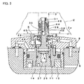
- Fig. 3 is a view similar to Fig. 1A, illustrating a locked state of the clamping apparatus.
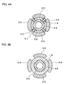
- Fig. 4A is an enlarged sectional view indicated by the arrow 4A-4A in Fig. 1A.
- Fig. 4B is an enlarged sectional view indicated by the arrow 4B-4B in Fig. 3.
- a cylindrical inner engaging member 38 is supported on an outer periphery of the pull rod 18 vertically movably, and between an outer peripheral surface of the lower half of the inner engaging member 38 and a through hole 8b of the housing 8 is formed a second annular gap 22. Thereby, the inner engaging member 38 is adapted to be radially movable with respect to the housing 8. Rotation of the inner engaging member 38 around its axis is blocked by a third rotation stopper pin 30. It is noted that, in this first embodiment, the upper half of the pull rod 18 is formed into a roughly square shape in a cross sectional view. Thereby, between an outer peripheral surface of the pull rod 18 and an inner peripheral surface of the inner engaging member 38 is formed a vertical passage 56 for compressed air for cleaning, as described later.
- the inner engaging member 38 is advanced upward by a coned disc spring (pressing means) 41, and the inner engaging member 38 is prevented from ascending by more than a predetermined range by a stopper 42.
- the coned disc spring 41 covers openings such as the through hole 8b of the housing 8 and the vertical hole 60 described later from above.
- outer engaging members 39 to be inserted into the engaging holes 3 of the work pallet 2 are arranged on an outer periphery of the inner engaging member 38 circumferentially at intervals.
- the plurality of outer engaging members 39 are adapted so as to wedge-engage with the inner engaging member 38 from above, and an output portion 46 of the pull rod 18 is connected to these outer engaging members 39.
- a cap-shaped cover member 31 is fixed to an upper portion of the pull rod 18 by a bolt 32, and between an upper portion of the cover member 31 and a ring 33 supported on an upper portion of the pull rod 18 are inserted upper flanges 40 of the outer engaging members 39 radially movably while their vertical relative movements are blocked.
- Guide pins 43 are projected from the outer periphery of the inner engaging member 38, and the pin projecting portions are inserted between the adjacent outer engaging members 39 and 39 respectively. Thereby, the plurality of outer engaging members 39 are guided vertically. Furthermore, a ring-shaped flat spring (returning means) 44 is attached to outer peripheral surfaces of the plurality of outer engaging members 39. The flat spring 44 urges each of the outer engaging members 39 radially inward. It is noted that on an outer periphery of the upper half of the cover member 31 is formed a tapered guide surface 36 that narrows upward.
- support rods 48 are press-fitted circumferentially at intervals into an upper surface of the housing 8.
- the support surfaces S provided on the upper surfaces of the support rods 48 is adapted so as to receive the supported surface 2a of the work pallet 2.
- the support rods 48 are arranged with phases corresponding to the projecting directions of the guide pins 43 respectively.
- the pull rod 18 is projected further upward than the support surfaces S.
- a detection nozzle hole 49 for seating confirmation In an arbitrary support rod 48 of the four support rods 48 is opened a detection nozzle hole 49 for seating confirmation, and to the detection nozzle hole 49 is adapted compressed air for detection to be supplied.
- the pressure in the detection nozzle hole 49 increases. It can be confirmed that the work pallet 2 is seated on the support rods 48 by detecting the increase in the pressure using a pressure switch or the like.
- a discharge port 51 for compressed air for cleaning (a cleaning fluid)
- the discharge ports 51 are directed toward the support surfaces S respectively.
- the outer peripheral surface of the cover member 31 In the outer peripheral surface of the cover member 31 are opened another plurality of discharge ports 52 for compressed air for cleaning.
- the clamping apparatus arranged as above operates as follows and as mainly illustrated in Fig. 1A and Fig. 3.
- pressurized oil in the lock chamber 13 has been discharged, and pressurized oil has been supplied to the release chamber 14.
- the drive piston 11 has raised the pull rod 18, and the pull rod 18 has raised the outer engaging members 39 via the cover member 31 and the ring 33, resulting in that the outer engaging members 39 has been switched into a contracted state.
- the inner engaging member 38 has ascended by an advancing stroke by the coned disc spring 41 and slightly made a tapered engagement with the outer engaging members 39 or faced the outer engaging member 39 with small gaps left therebetween.
- the compressed air for cleaning is also supplied to the vertical hole 60 formed in a peripheral wall of the through hole 8b of the housing 8, and the compressed air can be discharged horizontally from a gap between an upper end of the coned disc spring 41 and the inner engaging member 38 or a gap between a lower end of the coned disc spring 41 and the housing 8.
- the work pallet 2 is lowered while keeping the releasing state, and the engaging hole 3 is fitted onto the plurality of outer engaging members 39.
- compressed air discharged from the other discharge port 52 diagonally upward can sufficiently clean the engaging hole 3.
- the pressurized oil in the release chamber 14 is discharged and pressurized oil is supplied to the lock chamber 13.
- the piston 11 lowers the outer engaging member 39 via the pull rod 18, and the tapered inner peripheral surfaces of the outer engaging members 39 gradually make wedge-engagement with the tapered wedge surfaces 47 of the inner engaging member 38.
- the outer engaging members 39 expand via the inner engaging member 38 held substantially at an raised position by means of the urging force of the coned disc spring 41, and the outer engaging members 39 comes into contact with the engaging hole 3. Thereafter, the outer engaging members 39 expand while compressing the coned disc spring 41 downward via the inner engaging member 38, and come into close contact with the engaging hole 3, and simultaneously, the outer engaging members 39 force the inner engaging member 38 to retreat downward against the urging force of the coned disc spring 41. Successively, as illustrated in Fig. 3, the inner engaging member 38 is received by a projection 61 of the peripheral wall of the through hole 8b at the upper portion of the housing 8 via the coned disc spring 41.
- the outer engaging members 39 are strongly wedge-engaged with the received inner engaging member 38 and expand, and the outer engaging members 39 come into strong and close contact with the engaging hole 3.
- the pull rod 18 strongly presses the supported surface 2a of the work pallet 2 against the support surfaces S of the first block 1 via the outer engaging members 39, which are in the strong and close contact state with the engaging hole 3.
- the outer engaging members 39 operate as follows during the locking operation. After coming into close contact with the engaging hole 3, the outer engaging members 39 move the inner engaging member 38 downward against the coned disc spring (pressing means) 41, whereby moving downward while sliding on the engaging hole 3. Then, as described above, when the downward movement of the outer engaging members 39 are blocked, the outer engaging members 39 come into strong and close contact with the engaging hole 3 and strongly press the second block 2 against the first block 1.
- the outer engaging members 39 operate as follows during locking operation. After coming into close contact with the engaging hole 3, the outer engaging members 39 in a close contact state move the second block 2 toward the first block 1 via the engaging hole 3. Then, as described above, when the downward movement of the outer engaging members 39 is blocked, the outer engaging members 39 come into strong and close contact with the engaging hole 3 and strongly press the second block 2 against the first block 1.
- the pressurized oil in the lock chamber 13 is discharged and pressurized oil is supplied to the release chamber 14.
- the drive piston 11 raises the outer engaging members 39 via the pull rod 18 and the outer engaging members 39 are contracted by the flat spring 44, resulting in that the locked state is released.
- the first embodiment may be changed as follows. Instead of providing the plurality of support surfaces S circumferentially, a support surface may be formed into a ring shape in a plan view on the upper surface of the flange 8a of the housing 8. One or a plurality of support surfaces S may be provided on the base plate 6 instead of being provided on the housing 8. The base plate 6 and the housing 8 may be formed integrally instead of separately (individually).
- the balancing spring 27 is preferable for smooth horizontal movement of the pull rod 18, however, the balancing spring 27 can be omitted depending on use conditions of the clamping apparatus.
- the coned disc spring 41 may be replaced with a compression coil spring or rubber or the like.
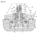
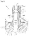
- Fig. 5A and Fig. 5B, Fig. 6A and Fig. 6B, Fig. 7A and Fig. 7B, Fig. 8, Fig. 10, and Fig. 11 illustrate second through seventh embodiments, respectively.
- components similar to those of the first embodiment will be designated by the same numerals as a general rule.
- the outer engaging members 39 may be two, three, or five or more instead of the four presented as an example.
- Shape of a wedge space W between the inner engaging member 38 and the outer engaging members 39 is not limited to the shape presented as an example, and a person skilled in the art can variously change it. For example, it is also allowed that an intermediate member is interposed between the wedge surface 47 of the inner engaging member 38 and the outer engaging members 39.
- the method for driving the drive piston (drive member) 11 may be a hydraulic single-acting one instead of the hydraulic double-acting one presented as an example.
- a spring-lock type and a spring-release type may be employed.
- the pressure fluid to be used for locking or releasing may be a gas such as compressed air instead of pressurized oil.
- the cleaning fluid may be a liquid instead of the compressed air presented as an example.
- the combination of the first block and the second block may be the combination of a table of a machine tool and a work pallet, the combination of a work pallet and a jig base, the combination of a jig base and a work piece, or the combination of a working jig such as a welding jig and a working article such as a work piece, instead of the combination of the base plate 6 and the work pallet 2 presented as an example.
Landscapes
- Engineering & Computer Science (AREA)
- Mechanical Engineering (AREA)
- Jigs For Machine Tools (AREA)
- Lock And Its Accessories (AREA)
- Electrical Discharge Machining, Electrochemical Machining, And Combined Machining (AREA)
- Vehicle Body Suspensions (AREA)
Applications Claiming Priority (2)
| Application Number | Priority Date | Filing Date | Title |
|---|---|---|---|
| JP2003279714 | 2003-07-25 | ||
| PCT/JP2004/009812 WO2005009676A1 (ja) | 2003-07-25 | 2004-07-09 | クランプ装置 |
Publications (3)
| Publication Number | Publication Date |
|---|---|
| EP1649973A1 true EP1649973A1 (de) | 2006-04-26 |
| EP1649973A4 EP1649973A4 (de) | 2008-04-02 |
| EP1649973B1 EP1649973B1 (de) | 2009-09-02 |
Family
ID=34100828
Family Applications (1)
| Application Number | Title | Priority Date | Filing Date |
|---|---|---|---|
| EP04747280A Expired - Lifetime EP1649973B1 (de) | 2003-07-25 | 2004-07-09 | Klemmvorrichtung |
Country Status (9)
| Country | Link |
|---|---|
| US (1) | US20060226591A1 (de) |
| EP (1) | EP1649973B1 (de) |
| JP (1) | JP4619950B2 (de) |
| KR (1) | KR20060037336A (de) |
| CN (1) | CN100413642C (de) |
| AT (1) | ATE441497T1 (de) |
| DE (1) | DE602004022948D1 (de) |
| TW (1) | TW200514648A (de) |
| WO (1) | WO2005009676A1 (de) |
Families Citing this family (16)
| Publication number | Priority date | Publication date | Assignee | Title |
|---|---|---|---|---|
| DE602004028641D1 (de) * | 2003-10-20 | 2010-09-23 | Kosmek Ltd | Positioniervorrichtung und diese aufweisendes klemmsystem |
| DE602006013349D1 (de) * | 2005-11-28 | 2010-05-12 | Kosmek Ltd | Klemmvorrichtung und solch eine vorrichtung verwendendes klemmsystem |
| KR100725601B1 (ko) * | 2006-06-23 | 2007-06-11 | 이현화 | 머시닝 센터의 척킹장치 |
| JP4837532B2 (ja) * | 2006-10-19 | 2011-12-14 | 株式会社コスメック | コレット式クランプ |
| FR2909914B1 (fr) * | 2006-12-15 | 2009-06-26 | Thales Sa | Dispositif de fixation rapide d'un ensemble mecanique sur un support |
| CH699231B1 (de) * | 2008-07-22 | 2012-03-30 | Erowa Ag | Spanneinrichtung. |
| JP5435908B2 (ja) * | 2008-08-06 | 2014-03-05 | パスカルエンジニアリング株式会社 | クランプ装置 |
| JP5885822B2 (ja) * | 2010-03-01 | 2016-03-16 | パスカルエンジニアリング株式会社 | クランプ装置 |
| JP5674191B2 (ja) * | 2010-03-01 | 2015-02-25 | パスカルエンジニアリング株式会社 | クランプ装置 |
| CN103237624B (zh) * | 2010-12-02 | 2016-08-10 | 克斯美库股份有限公司 | 夹紧装置 |
| CN102218670B (zh) * | 2011-05-31 | 2013-04-24 | 浙江吉利汽车研究院有限公司 | 一种活塞的定位工装夹具 |
| ITUB20160781A1 (it) * | 2016-01-27 | 2017-07-27 | Hydroblock S R L | Dispositivo per il bloccaggio di pezzi su macchine utensili |
| JP7093542B2 (ja) * | 2018-05-01 | 2022-06-30 | 株式会社コスメック | 位置決め装置 |
| CN109128875A (zh) * | 2018-11-20 | 2019-01-04 | 宝鸡虢西磨棱机制造有限公司 | 一种高精度回转工作台 |
| JP6849155B2 (ja) * | 2019-03-27 | 2021-03-24 | 豊和工業株式会社 | チャックの防塵機構およびチャック |
| CN113687112B (zh) * | 2021-09-14 | 2023-11-21 | 国网山东省电力公司鱼台县供电公司 | 一种避雷器试验装置 |
Family Cites Families (13)
| Publication number | Priority date | Publication date | Assignee | Title |
|---|---|---|---|---|
| US4059036A (en) * | 1976-07-06 | 1977-11-22 | T.I. (Group Services) Limited | Shearing hollow stock |
| US4767125A (en) * | 1986-06-25 | 1988-08-30 | Owens-Illinois Television Products Inc. | Expansion chuck |
| CN1109399A (zh) * | 1994-04-01 | 1995-10-04 | 厄罗瓦公司 | 工件夹紧装置 |
| DE19624382C1 (de) * | 1996-06-19 | 1998-01-02 | Bosch Gmbh Robert | Klemmvorrichtung |
| JP3954704B2 (ja) * | 1997-10-31 | 2007-08-08 | 株式会社コスメック | クランプ装置 |
| JP3550010B2 (ja) * | 1997-12-24 | 2004-08-04 | 株式会社コスメック | クランプ装置 |
| JP3338669B2 (ja) * | 1999-08-03 | 2002-10-28 | 株式会社コスメック | データム機能付きクランプ装置 |
| JP2002361533A (ja) * | 2001-06-07 | 2002-12-18 | Kosmek Ltd | データム機能付きクランプ装置 |
| JP5064622B2 (ja) * | 2001-09-21 | 2012-10-31 | パスカルエンジニアリング株式会社 | クランプ装置 |
| JP2003181730A (ja) * | 2001-10-12 | 2003-07-02 | Kosmek Ltd | クランプ装置 |
| JP4118145B2 (ja) * | 2002-02-22 | 2008-07-16 | 株式会社コスメック | 自動位置決め装置 |
| TWI262835B (en) * | 2002-02-22 | 2006-10-01 | Kosmek Kabushiki Kaisha | Automatic positioning device |
| JP2004223702A (ja) * | 2002-11-29 | 2004-08-12 | Kosmek Ltd | 位置決め装置 |
-
2004
- 2004-07-09 JP JP2005511995A patent/JP4619950B2/ja not_active Expired - Fee Related
- 2004-07-09 AT AT04747280T patent/ATE441497T1/de not_active IP Right Cessation
- 2004-07-09 DE DE602004022948T patent/DE602004022948D1/de not_active Expired - Lifetime
- 2004-07-09 KR KR1020067000586A patent/KR20060037336A/ko not_active Abandoned
- 2004-07-09 WO PCT/JP2004/009812 patent/WO2005009676A1/ja not_active Ceased
- 2004-07-09 EP EP04747280A patent/EP1649973B1/de not_active Expired - Lifetime
- 2004-07-09 CN CNB2004800216068A patent/CN100413642C/zh not_active Expired - Fee Related
- 2004-07-09 US US10/565,503 patent/US20060226591A1/en not_active Abandoned
- 2004-07-16 TW TW093121382A patent/TW200514648A/zh not_active IP Right Cessation
Non-Patent Citations (2)
| Title |
|---|
| No further relevant documents disclosed * |
| See also references of WO2005009676A1 * |
Also Published As
| Publication number | Publication date |
|---|---|
| US20060226591A1 (en) | 2006-10-12 |
| ATE441497T1 (de) | 2009-09-15 |
| TW200514648A (en) | 2005-05-01 |
| EP1649973B1 (de) | 2009-09-02 |
| CN1829584A (zh) | 2006-09-06 |
| JP4619950B2 (ja) | 2011-01-26 |
| JPWO2005009676A1 (ja) | 2007-04-19 |
| EP1649973A4 (de) | 2008-04-02 |
| WO2005009676A1 (ja) | 2005-02-03 |
| TWI334372B (de) | 2010-12-11 |
| KR20060037336A (ko) | 2006-05-03 |
| CN100413642C (zh) | 2008-08-27 |
| DE602004022948D1 (de) | 2009-10-15 |
Similar Documents
| Publication | Publication Date | Title |
|---|---|---|
| EP1649973B1 (de) | Klemmvorrichtung | |
| EP1961516B1 (de) | Klemmvorrichtung und solch eine vorrichtung verwendendes klemmsystem | |
| EP1598144B1 (de) | Klemmvorrichtung und klemmsystem damit | |
| EP1078713B1 (de) | Spannvorrichtung mit Ausrichtfunktion | |
| US7303186B2 (en) | Aligning drive mechanism and positioning apparatus having this mechanism | |
| US7168695B2 (en) | Positioning device | |
| US7232121B2 (en) | Clamping device | |
| EP1666197B1 (de) | Klemmvorrichtung | |
| US6641127B2 (en) | Clamping apparatus | |
| EP1338374A1 (de) | Vorrichtung zur automatischen Positionierung eines beweglichen Teiles auf einen Referenzteil | |
| JP2005040922A (ja) | クランプ装置 | |
| CN100486761C (zh) | 定位装置和具有该定位装置的夹持系统 | |
| US7377505B2 (en) | Clamping apparatus and clamping system | |
| JP2003181730A (ja) | クランプ装置 | |
| JP4607635B2 (ja) | クランプ装置およびその装置を利用したクランピングシステム |
Legal Events
| Date | Code | Title | Description |
|---|---|---|---|
| PUAI | Public reference made under article 153(3) epc to a published international application that has entered the european phase |
Free format text: ORIGINAL CODE: 0009012 |
|
| 17P | Request for examination filed |
Effective date: 20060120 |
|
| AK | Designated contracting states |
Kind code of ref document: A1 Designated state(s): AT BE BG CH CY CZ DE DK EE ES FI FR GB GR HU IE IT LI LU MC NL PL PT RO SE SI SK TR |
|
| DAX | Request for extension of the european patent (deleted) | ||
| A4 | Supplementary search report drawn up and despatched |
Effective date: 20080305 |
|
| RIC1 | Information provided on ipc code assigned before grant |
Ipc: B23Q 1/00 20060101ALI20080228BHEP Ipc: B23Q 3/00 20060101AFI20050207BHEP |
|
| 17Q | First examination report despatched |
Effective date: 20080602 |
|
| GRAP | Despatch of communication of intention to grant a patent |
Free format text: ORIGINAL CODE: EPIDOSNIGR1 |
|
| GRAS | Grant fee paid |
Free format text: ORIGINAL CODE: EPIDOSNIGR3 |
|
| GRAA | (expected) grant |
Free format text: ORIGINAL CODE: 0009210 |
|
| AK | Designated contracting states |
Kind code of ref document: B1 Designated state(s): AT BE BG CH CY CZ DE DK EE ES FI FR GB GR HU IE IT LI LU MC NL PL PT RO SE SI SK TR |
|
| REG | Reference to a national code |
Ref country code: CH Ref legal event code: EP |
|
| REG | Reference to a national code |
Ref country code: IE Ref legal event code: FG4D |
|
| REF | Corresponds to: |
Ref document number: 602004022948 Country of ref document: DE Date of ref document: 20091015 Kind code of ref document: P |
|
| PG25 | Lapsed in a contracting state [announced via postgrant information from national office to epo] |
Ref country code: SE Free format text: LAPSE BECAUSE OF FAILURE TO SUBMIT A TRANSLATION OF THE DESCRIPTION OR TO PAY THE FEE WITHIN THE PRESCRIBED TIME-LIMIT Effective date: 20090902 Ref country code: FI Free format text: LAPSE BECAUSE OF FAILURE TO SUBMIT A TRANSLATION OF THE DESCRIPTION OR TO PAY THE FEE WITHIN THE PRESCRIBED TIME-LIMIT Effective date: 20090902 |
|
| NLV1 | Nl: lapsed or annulled due to failure to fulfill the requirements of art. 29p and 29m of the patents act | ||
| PG25 | Lapsed in a contracting state [announced via postgrant information from national office to epo] |
Ref country code: PL Free format text: LAPSE BECAUSE OF FAILURE TO SUBMIT A TRANSLATION OF THE DESCRIPTION OR TO PAY THE FEE WITHIN THE PRESCRIBED TIME-LIMIT Effective date: 20090902 Ref country code: NL Free format text: LAPSE BECAUSE OF FAILURE TO SUBMIT A TRANSLATION OF THE DESCRIPTION OR TO PAY THE FEE WITHIN THE PRESCRIBED TIME-LIMIT Effective date: 20090902 Ref country code: SI Free format text: LAPSE BECAUSE OF FAILURE TO SUBMIT A TRANSLATION OF THE DESCRIPTION OR TO PAY THE FEE WITHIN THE PRESCRIBED TIME-LIMIT Effective date: 20090902 |
|
| PG25 | Lapsed in a contracting state [announced via postgrant information from national office to epo] |
Ref country code: CY Free format text: LAPSE BECAUSE OF FAILURE TO SUBMIT A TRANSLATION OF THE DESCRIPTION OR TO PAY THE FEE WITHIN THE PRESCRIBED TIME-LIMIT Effective date: 20090902 |
|
| PG25 | Lapsed in a contracting state [announced via postgrant information from national office to epo] |
Ref country code: PT Free format text: LAPSE BECAUSE OF FAILURE TO SUBMIT A TRANSLATION OF THE DESCRIPTION OR TO PAY THE FEE WITHIN THE PRESCRIBED TIME-LIMIT Effective date: 20100104 Ref country code: EE Free format text: LAPSE BECAUSE OF FAILURE TO SUBMIT A TRANSLATION OF THE DESCRIPTION OR TO PAY THE FEE WITHIN THE PRESCRIBED TIME-LIMIT Effective date: 20090902 Ref country code: CZ Free format text: LAPSE BECAUSE OF FAILURE TO SUBMIT A TRANSLATION OF THE DESCRIPTION OR TO PAY THE FEE WITHIN THE PRESCRIBED TIME-LIMIT Effective date: 20090902 Ref country code: ES Free format text: LAPSE BECAUSE OF FAILURE TO SUBMIT A TRANSLATION OF THE DESCRIPTION OR TO PAY THE FEE WITHIN THE PRESCRIBED TIME-LIMIT Effective date: 20091213 Ref country code: RO Free format text: LAPSE BECAUSE OF FAILURE TO SUBMIT A TRANSLATION OF THE DESCRIPTION OR TO PAY THE FEE WITHIN THE PRESCRIBED TIME-LIMIT Effective date: 20090902 |
|
| PG25 | Lapsed in a contracting state [announced via postgrant information from national office to epo] |
Ref country code: SK Free format text: LAPSE BECAUSE OF FAILURE TO SUBMIT A TRANSLATION OF THE DESCRIPTION OR TO PAY THE FEE WITHIN THE PRESCRIBED TIME-LIMIT Effective date: 20090902 |
|
| PG25 | Lapsed in a contracting state [announced via postgrant information from national office to epo] |
Ref country code: AT Free format text: LAPSE BECAUSE OF FAILURE TO SUBMIT A TRANSLATION OF THE DESCRIPTION OR TO PAY THE FEE WITHIN THE PRESCRIBED TIME-LIMIT Effective date: 20090902 Ref country code: BE Free format text: LAPSE BECAUSE OF FAILURE TO SUBMIT A TRANSLATION OF THE DESCRIPTION OR TO PAY THE FEE WITHIN THE PRESCRIBED TIME-LIMIT Effective date: 20090902 |
|
| PLBE | No opposition filed within time limit |
Free format text: ORIGINAL CODE: 0009261 |
|
| STAA | Information on the status of an ep patent application or granted ep patent |
Free format text: STATUS: NO OPPOSITION FILED WITHIN TIME LIMIT |
|
| PG25 | Lapsed in a contracting state [announced via postgrant information from national office to epo] |
Ref country code: DK Free format text: LAPSE BECAUSE OF FAILURE TO SUBMIT A TRANSLATION OF THE DESCRIPTION OR TO PAY THE FEE WITHIN THE PRESCRIBED TIME-LIMIT Effective date: 20090902 |
|
| 26N | No opposition filed |
Effective date: 20100603 |
|
| PG25 | Lapsed in a contracting state [announced via postgrant information from national office to epo] |
Ref country code: GR Free format text: LAPSE BECAUSE OF FAILURE TO SUBMIT A TRANSLATION OF THE DESCRIPTION OR TO PAY THE FEE WITHIN THE PRESCRIBED TIME-LIMIT Effective date: 20091203 |
|
| PGFP | Annual fee paid to national office [announced via postgrant information from national office to epo] |
Ref country code: FR Payment date: 20100720 Year of fee payment: 7 Ref country code: GB Payment date: 20100629 Year of fee payment: 7 Ref country code: IT Payment date: 20100726 Year of fee payment: 7 |
|
| PG25 | Lapsed in a contracting state [announced via postgrant information from national office to epo] |
Ref country code: MC Free format text: LAPSE BECAUSE OF NON-PAYMENT OF DUE FEES Effective date: 20100731 |
|
| REG | Reference to a national code |
Ref country code: CH Ref legal event code: PL |
|
| PG25 | Lapsed in a contracting state [announced via postgrant information from national office to epo] |
Ref country code: LI Free format text: LAPSE BECAUSE OF NON-PAYMENT OF DUE FEES Effective date: 20100731 Ref country code: CH Free format text: LAPSE BECAUSE OF NON-PAYMENT OF DUE FEES Effective date: 20100731 |
|
| PG25 | Lapsed in a contracting state [announced via postgrant information from national office to epo] |
Ref country code: IE Free format text: LAPSE BECAUSE OF NON-PAYMENT OF DUE FEES Effective date: 20100709 |
|
| PGFP | Annual fee paid to national office [announced via postgrant information from national office to epo] |
Ref country code: DE Payment date: 20110722 Year of fee payment: 8 |
|
| GBPC | Gb: european patent ceased through non-payment of renewal fee |
Effective date: 20110709 |
|
| REG | Reference to a national code |
Ref country code: FR Ref legal event code: ST Effective date: 20120330 |
|
| PG25 | Lapsed in a contracting state [announced via postgrant information from national office to epo] |
Ref country code: FR Free format text: LAPSE BECAUSE OF NON-PAYMENT OF DUE FEES Effective date: 20110801 |
|
| PG25 | Lapsed in a contracting state [announced via postgrant information from national office to epo] |
Ref country code: IT Free format text: LAPSE BECAUSE OF NON-PAYMENT OF DUE FEES Effective date: 20110709 |
|
| PG25 | Lapsed in a contracting state [announced via postgrant information from national office to epo] |
Ref country code: GB Free format text: LAPSE BECAUSE OF NON-PAYMENT OF DUE FEES Effective date: 20110709 |
|
| PG25 | Lapsed in a contracting state [announced via postgrant information from national office to epo] |
Ref country code: HU Free format text: LAPSE BECAUSE OF FAILURE TO SUBMIT A TRANSLATION OF THE DESCRIPTION OR TO PAY THE FEE WITHIN THE PRESCRIBED TIME-LIMIT Effective date: 20100303 Ref country code: BG Free format text: LAPSE BECAUSE OF FAILURE TO SUBMIT A TRANSLATION OF THE DESCRIPTION OR TO PAY THE FEE WITHIN THE PRESCRIBED TIME-LIMIT Effective date: 20090902 Ref country code: LU Free format text: LAPSE BECAUSE OF NON-PAYMENT OF DUE FEES Effective date: 20100709 |
|
| PG25 | Lapsed in a contracting state [announced via postgrant information from national office to epo] |
Ref country code: TR Free format text: LAPSE BECAUSE OF FAILURE TO SUBMIT A TRANSLATION OF THE DESCRIPTION OR TO PAY THE FEE WITHIN THE PRESCRIBED TIME-LIMIT Effective date: 20090902 |
|
| PG25 | Lapsed in a contracting state [announced via postgrant information from national office to epo] |
Ref country code: DE Free format text: LAPSE BECAUSE OF NON-PAYMENT OF DUE FEES Effective date: 20130201 |
|
| REG | Reference to a national code |
Ref country code: DE Ref legal event code: R119 Ref document number: 602004022948 Country of ref document: DE Effective date: 20130201 |