EP1650102A1 - Mécanisme de direction - Google Patents
Mécanisme de direction Download PDFInfo
- Publication number
- EP1650102A1 EP1650102A1 EP05021230A EP05021230A EP1650102A1 EP 1650102 A1 EP1650102 A1 EP 1650102A1 EP 05021230 A EP05021230 A EP 05021230A EP 05021230 A EP05021230 A EP 05021230A EP 1650102 A1 EP1650102 A1 EP 1650102A1
- Authority
- EP
- European Patent Office
- Prior art keywords
- rack
- steering
- pressure piece
- support means
- force
- Prior art date
- Legal status (The legal status is an assumption and is not a legal conclusion. Google has not performed a legal analysis and makes no representation as to the accuracy of the status listed.)
- Withdrawn
Links
- 230000007935 neutral effect Effects 0.000 claims description 14
- 229920000642 polymer Polymers 0.000 claims description 5
- 230000015572 biosynthetic process Effects 0.000 claims description 4
- 238000007493 shaping process Methods 0.000 claims 1
- 238000013016 damping Methods 0.000 description 4
- 238000006073 displacement reaction Methods 0.000 description 4
- 230000002596 correlated effect Effects 0.000 description 2
- 230000007423 decrease Effects 0.000 description 2
- 230000001419 dependent effect Effects 0.000 description 2
- 238000010586 diagram Methods 0.000 description 2
- 239000002184 metal Substances 0.000 description 2
- 230000002238 attenuated effect Effects 0.000 description 1
- 230000000875 corresponding effect Effects 0.000 description 1
- 230000013011 mating Effects 0.000 description 1
- 238000005096 rolling process Methods 0.000 description 1
Images


Classifications
-
- B—PERFORMING OPERATIONS; TRANSPORTING
- B62—LAND VEHICLES FOR TRAVELLING OTHERWISE THAN ON RAILS
- B62D—MOTOR VEHICLES; TRAILERS
- B62D3/00—Steering gears
- B62D3/02—Steering gears mechanical
- B62D3/12—Steering gears mechanical of rack-and-pinion type
- B62D3/123—Steering gears mechanical of rack-and-pinion type characterised by pressure yokes
-
- F—MECHANICAL ENGINEERING; LIGHTING; HEATING; WEAPONS; BLASTING
- F16—ENGINEERING ELEMENTS AND UNITS; GENERAL MEASURES FOR PRODUCING AND MAINTAINING EFFECTIVE FUNCTIONING OF MACHINES OR INSTALLATIONS; THERMAL INSULATION IN GENERAL
- F16H—GEARING
- F16H55/00—Elements with teeth or friction surfaces for conveying motion; Worms, pulleys or sheaves for gearing mechanisms
- F16H55/02—Toothed members; Worms
- F16H55/26—Racks
- F16H55/28—Special devices for taking up backlash
- F16H55/283—Special devices for taking up backlash using pressure yokes
Definitions
- the invention relates to a steering gear according to the preamble of claim 1.
- steering gear for motor vehicles are known in which a connected to the further steering of the wheels rack can be moved by means of a driven steering pinion in its longitudinal direction. It is to ensure the backlash of the steering is known to stretch the rack by means of a pressure piece against the steering pinion, so as to achieve a fully play-free meshing of rack and pinion. Basically, such a bias of the rack leads to increase a push-through force of the rack in its longitudinal direction.
- Modern chassis geometries are often designed so that an acting on the wheels taken restoring force in the direction of a neutral position of the steering (straight ahead) while driving is low. This leads to problems in the steering of the vehicle, in particular vibrations can occur around the neutral position around.
- the first pressure piece engages via a first support means and the second pressure piece via a second support means in each case on the rack.
- the first support means consists of a polymer and more preferably the second support means is formed as a metallic, rotatable bearing means.
- the first support means has a comparatively high friction with the rack and the second support means a comparatively low friction.
- the first support means may advantageously cooperate with a non-perpendicular to the direction of force of the first pressure pad support surface of the rack.
- the rack on a formation wherein the second support means cooperates in a particular associated with a neutral position of the rack displacement area with the formation.
- this formation can be a depression of a support surface of the rack associated with the second support means.
- the second pressure piece is received on the first pressure piece.
- the first pressure piece is supported with a first spring against the steering housing, and the second Pressure piece is supported with a second spring against the first pressure piece.
- a mutual influencing of the supporting forces acting on the support means is made possible in a simple manner, so that approximately in positions of the rack, in which a high force acts on the first support means, a correspondingly lower force acts on the second support means and vice versa. Due to sauchten rubbing the support means can then be achieved in a simple manner a variable push-through force, wherein the summed support force of the two pressure pieces, by which the rack is kept free of play in their intermeshing, preferably not changed.
- the steering gear 1 comprises a steering housing 2, in which a toothed rack 3 is displaceably guided in its longitudinal direction about a steering path.
- the ends of the rack are connected to further, not shown steering linkage for pivoting the front wheels of a motor vehicle.
- the rack 3 in the present case has a Y-shaped cross-section (see FIG. 1).
- the rack 3 comprises a series of teeth 3a, which with a rotatably received in the steering housing 2 gear or steering pinion 4 are meshed.
- the steering pinion 4 is rotatably driven by the further steering means (not shown) of the motor vehicle, which may be both a purely manual drive by a shaft rotatable by means of a steering wheel and a motor or hydraulic drive.
- the described steering gear can thus be used both for power steering systems and for power-assisted steering systems.
- the bearing and / or the flexibility of the rack is such that it has sufficient play in its direction perpendicular to its longitudinal direction and the axis of rotation of the steering pinion (hereinafter referred to as normal direction) sufficient clearance to allow a play-free mating with the steering pinion.
- normal direction the axis of rotation of the steering pinion
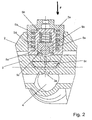
- the rack is subjected to force in its normal direction with a supporting force F (see FIG. 2).
- the supporting force F is exerted by means of a first pressure piece 5 and a second pressure piece 6 on the opposite side of the toothed rack of the rack 3.
- the first pressure piece 5 comprises a pressure piece body 5a, which is received in a movable manner in the normal direction in a corresponding recess of the steering housing 2.
- a first spring 5b which is designed as a spiral spring, supports the pressure piece body 5a against a firmly connected to the steering housing 2 tail 2a.
- the pressure piece body 5a is provided with two flanks, each inclined by approximately 45 degrees, against the normal direction, on which a first support means 5c is mounted.
- the first support means 5c comprises a support covering consisting of an elastic polymer for each of the two flanks.
- Each of the support pads engages a respective first support surface 3b, which is located in each case on the two of the toothing opposite leg surfaces of the Y-shaped rack.
- a blind hole-like recess in the pressure piece body 5a is provided, in which a second pressure piece 6 is received.
- the second pressure piece 6 comprises a second pressure piece body 6a which is movably guided in the recess of the first pressure piece body in the normal direction and supported by a second spring 6b against a bottom of the first pressure piece body 5a, the second spring 6b is formed as the first spring 5b as a helical spring ,
- the displacement of the second pressure piece in the direction of the rack 3 is limited by means of a recorded on the first pressure piece body 5a stop ring 5d.
- the stop ring 5d has a sufficient opening for the passage of a second support means 6c accommodated on the second pressure piece body.
- the second support means 6c is shown in the drawings as a ball bearing, which is guided in a hemispherical recess of the first pressure piece body 5a. However, it may also be a rotatably mounted roller or another known per se, low-friction support means.
- the second support means 6c rolls on a second support surface 3c of the rack 3, which corresponds to an end face of the central trunk of the Y-shaped rack.
- the transmitted through the second support means 6c on the rack forces act here exclusively in the normal direction.
- the second support surface 3c of the toothed rack 3 has a depression 3d into which the second support means or the bearing ball 6c engages in the position of the toothed rack 3 according to FIG. This position of the rack is assigned to the neutral position of the steering (straight ahead).
- the total force F which is exerted by the pressure pieces 5, 6 on the rack 3 in the normal direction, is composed of a partial force F1 of the first pressure piece 5 and a partial force F2 of the second pressure piece 6 together.
- the partial force F1 is transmitted by the first support means 5c and the partial force F2 by the second support means 6c. Due to the different design of the support means 5c, 6c on the one hand as a polymer and on the other as a metallic bearing ball or bearing roller significantly different frictional forces, the movement of the rack 3 in Their longitudinal direction are opposite. At least the frictional forces of the first support means 5c (polymer) are essential contributions to the total push-through force of the rack 3 in its longitudinal direction.
- the second support means 6c has due to the design of a rolling storage of metal on metal on a very low coefficient of friction, so that the push-through force decreases upon deflection of the rack 3 from its neutral position.
- a force acting on the second support means 6c axial force thus reduces the force acting on the first support means 5c axial force by their amount and correspondingly reduces the friction between the support means 5c and the rack and thus the push-through force.
- this decrease in the push-through force can be designed more or less continuously.
- the springs 5b, 6b and thus of the partial forces F1 and F2 the change in the push-through force can be predetermined.
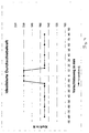
- FIG. 4 shows a schematic diagram with the course of the push-through force of a steering system according to the exemplary embodiment described above.
- the displacement force is plotted via the displacement path, with the straight-ahead position in the middle.
Landscapes
- Engineering & Computer Science (AREA)
- General Engineering & Computer Science (AREA)
- Mechanical Engineering (AREA)
- Chemical & Material Sciences (AREA)
- Combustion & Propulsion (AREA)
- Transportation (AREA)
- Transmission Devices (AREA)
- Gear Transmission (AREA)
Applications Claiming Priority (1)
| Application Number | Priority Date | Filing Date | Title |
|---|---|---|---|
| DE200410051494 DE102004051494A1 (de) | 2004-10-21 | 2004-10-21 | Lenkgetriebe |
Publications (1)
| Publication Number | Publication Date |
|---|---|
| EP1650102A1 true EP1650102A1 (fr) | 2006-04-26 |
Family
ID=35276659
Family Applications (1)
| Application Number | Title | Priority Date | Filing Date |
|---|---|---|---|
| EP05021230A Withdrawn EP1650102A1 (fr) | 2004-10-21 | 2005-09-29 | Mécanisme de direction |
Country Status (3)
| Country | Link |
|---|---|
| EP (1) | EP1650102A1 (fr) |
| CN (1) | CN1769119A (fr) |
| DE (1) | DE102004051494A1 (fr) |
Cited By (1)
| Publication number | Priority date | Publication date | Assignee | Title |
|---|---|---|---|---|
| EP2906459A4 (fr) * | 2012-09-30 | 2016-04-27 | Saint Gobain Performance Plast | Ensemble fourche de direction |
Families Citing this family (4)
| Publication number | Priority date | Publication date | Assignee | Title |
|---|---|---|---|---|
| DE102006052376A1 (de) * | 2006-11-07 | 2008-05-08 | Volkswagen Ag | Verfahren zur Bestimmung eines Druckstückspiels |
| DE102010051728A1 (de) * | 2010-11-19 | 2012-05-24 | Thyssenkrupp Presta Ag | Rollengelagerte Zahnstangenführung |
| DE102011109878A1 (de) * | 2011-08-10 | 2013-02-14 | Thyssenkrupp Presta Ag | Zahnstangenlenkgetriebe |
| DE102013210731B4 (de) | 2012-06-22 | 2025-03-13 | Ford Global Technologies, Llc | Druckstück für ein Zahnstangenlenkgetriebe für ein Fahrzeug |
Citations (6)
| Publication number | Priority date | Publication date | Assignee | Title |
|---|---|---|---|---|
| GB971490A (en) * | 1961-08-17 | 1964-09-30 | Alford & Alder Engineers Ltd | Improvements in or relating to steering mechanisms for automobile vehicles |
| JPS58110372A (ja) * | 1981-12-22 | 1983-06-30 | Nissan Motor Co Ltd | ラツク・ピニオン式ステアリング装置 |
| DE3515583A1 (de) * | 1984-05-01 | 1985-11-14 | Koyo Jidoki K.K., Kashihara, Nara | Zahnrad-zahnstangen-mechanismus in einer lenkvorrichtung |
| DE3613030A1 (de) * | 1985-04-17 | 1986-10-30 | Tokai TRW & Co., Ltd., Kasugai, Aichi | Lenkmechanismus fuer kraftfahrzeuge |
| JPS6362956A (ja) * | 1986-08-30 | 1988-03-19 | Tokai T R W Kk | ラツクギヤ支持装置 |
| EP0758605A1 (fr) * | 1995-08-15 | 1997-02-19 | Trw Inc. | Boîte de direction à crémaillère avec poussoir amélioré |
Family Cites Families (5)
| Publication number | Priority date | Publication date | Assignee | Title |
|---|---|---|---|---|
| GB1182719A (en) * | 1968-01-12 | 1970-03-04 | Burman & Sons Ltd | Rack and Pinion Steering Mechanism |
| JPS59184060A (ja) * | 1983-03-31 | 1984-10-19 | Tokai T R W Kk | ラツク・ピニオンギヤの支持装置 |
| JPS6189168A (ja) * | 1984-10-06 | 1986-05-07 | Tokai T R W Kk | ラツク・ピニオンステアリング機構 |
| DE3529447A1 (de) * | 1985-08-16 | 1987-03-05 | Audi Ag | Zahnstangen-lenkgetriebe |
| JP2001260905A (ja) * | 2000-03-14 | 2001-09-26 | Koyo Seiko Co Ltd | ラックピニオン式舵取り装置 |
-
2004
- 2004-10-21 DE DE200410051494 patent/DE102004051494A1/de not_active Withdrawn
-
2005
- 2005-09-29 EP EP05021230A patent/EP1650102A1/fr not_active Withdrawn
- 2005-10-21 CN CN 200510116362 patent/CN1769119A/zh active Pending
Patent Citations (6)
| Publication number | Priority date | Publication date | Assignee | Title |
|---|---|---|---|---|
| GB971490A (en) * | 1961-08-17 | 1964-09-30 | Alford & Alder Engineers Ltd | Improvements in or relating to steering mechanisms for automobile vehicles |
| JPS58110372A (ja) * | 1981-12-22 | 1983-06-30 | Nissan Motor Co Ltd | ラツク・ピニオン式ステアリング装置 |
| DE3515583A1 (de) * | 1984-05-01 | 1985-11-14 | Koyo Jidoki K.K., Kashihara, Nara | Zahnrad-zahnstangen-mechanismus in einer lenkvorrichtung |
| DE3613030A1 (de) * | 1985-04-17 | 1986-10-30 | Tokai TRW & Co., Ltd., Kasugai, Aichi | Lenkmechanismus fuer kraftfahrzeuge |
| JPS6362956A (ja) * | 1986-08-30 | 1988-03-19 | Tokai T R W Kk | ラツクギヤ支持装置 |
| EP0758605A1 (fr) * | 1995-08-15 | 1997-02-19 | Trw Inc. | Boîte de direction à crémaillère avec poussoir amélioré |
Non-Patent Citations (2)
| Title |
|---|
| PATENT ABSTRACTS OF JAPAN vol. 007, no. 217 (M - 245) 27 September 1983 (1983-09-27) * |
| PATENT ABSTRACTS OF JAPAN vol. 012, no. 286 (M - 727) 5 August 1988 (1988-08-05) * |
Cited By (1)
| Publication number | Priority date | Publication date | Assignee | Title |
|---|---|---|---|---|
| EP2906459A4 (fr) * | 2012-09-30 | 2016-04-27 | Saint Gobain Performance Plast | Ensemble fourche de direction |
Also Published As
| Publication number | Publication date |
|---|---|
| CN1769119A (zh) | 2006-05-10 |
| DE102004051494A1 (de) | 2006-04-27 |
Similar Documents
| Publication | Publication Date | Title |
|---|---|---|
| EP1807639B1 (fr) | Dispositif pour comprimer une cremaillere | |
| EP2763884B1 (fr) | Dispositif comportant un premier support de cames | |
| DE10049570A1 (de) | Elektrische Servolenkvorrichtung | |
| EP3853107A1 (fr) | Colonne de direction et système de direction à commande par câble | |
| DE102012219888A1 (de) | Zahnstange für eine Zahnstangenlenkung eines Kraftfahrzeuges | |
| DE102011003086A1 (de) | Zahnstangenlenkgetriebe und damit ausgestattete Servolenkung | |
| DE112016002670T5 (de) | Getriebeanordnung für elektrische Servolenkung | |
| EP2091801B1 (fr) | Direction à crémaillère | |
| EP1537346B1 (fr) | Dispositif de pression | |
| DE3537946C2 (fr) | ||
| DE102021200051A1 (de) | Lenksystem für ein Kraftfahrzeug | |
| DE3524480A1 (de) | Lenkgetriebe | |
| DE102011006816A1 (de) | Zahnstangenlenkgetriebe | |
| DE3334107C2 (fr) | ||
| DE102004051494A1 (de) | Lenkgetriebe | |
| EP0198824B1 (fr) | Servodirection hydraulique, en particulier pour vehicules a moteur | |
| DE102020102212A1 (de) | Aktuator | |
| DE2104037C3 (de) | Servolenksystem | |
| DE102012019654A1 (de) | Zahnstangenlenkgetriebe | |
| WO2011110512A1 (fr) | Élément de rattrapage de jeu présentant une clavette | |
| DE102005039318A1 (de) | Vorrichtung zum längenveränderlichen Verstellen eines Lenkers | |
| DE10354776A1 (de) | Zahnstangenlenkung | |
| DE102006043578A1 (de) | Vorrichtung zum Andrücken einer Zahnstange an ein mit der Zahnstange in Eingriff stehendes Ritzel | |
| DE4422556C1 (de) | Durch Servomotor unterstützte Zahnstangenlenkung | |
| DE10230600A1 (de) | Anpressvorrichtung |
Legal Events
| Date | Code | Title | Description |
|---|---|---|---|
| PUAI | Public reference made under article 153(3) epc to a published international application that has entered the european phase |
Free format text: ORIGINAL CODE: 0009012 |
|
| AK | Designated contracting states |
Kind code of ref document: A1 Designated state(s): AT BE BG CH CY CZ DE DK EE ES FI FR GB GR HU IE IS IT LI LT LU LV MC NL PL PT RO SE SI SK TR |
|
| AX | Request for extension of the european patent |
Extension state: AL BA HR MK YU |
|
| AKX | Designation fees paid | ||
| STAA | Information on the status of an ep patent application or granted ep patent |
Free format text: STATUS: THE APPLICATION IS DEEMED TO BE WITHDRAWN |
|
| 18D | Application deemed to be withdrawn |
Effective date: 20061027 |
|
| REG | Reference to a national code |
Ref country code: DE Ref legal event code: 8566 |