EP1650155A2 - Greifer für gestapelte Drahtgittermatten - Google Patents
Greifer für gestapelte Drahtgittermatten Download PDFInfo
- Publication number
- EP1650155A2 EP1650155A2 EP05022581A EP05022581A EP1650155A2 EP 1650155 A2 EP1650155 A2 EP 1650155A2 EP 05022581 A EP05022581 A EP 05022581A EP 05022581 A EP05022581 A EP 05022581A EP 1650155 A2 EP1650155 A2 EP 1650155A2
- Authority
- EP
- European Patent Office
- Prior art keywords
- arms
- grab
- wire mesh
- teeth
- grab according
- Prior art date
- Legal status (The legal status is an assumption and is not a legal conclusion. Google has not performed a legal analysis and makes no representation as to the accuracy of the status listed.)
- Withdrawn
Links
Images



Classifications
-
- B—PERFORMING OPERATIONS; TRANSPORTING
- B66—HOISTING; LIFTING; HAULING
- B66C—CRANES; LOAD-ENGAGING ELEMENTS OR DEVICES FOR CRANES, CAPSTANS, WINCHES, OR TACKLES
- B66C1/00—Load-engaging elements or devices attached to lifting or lowering gear of cranes or adapted for connection therewith for transmitting lifting forces to articles or groups of articles
- B66C1/10—Load-engaging elements or devices attached to lifting or lowering gear of cranes or adapted for connection therewith for transmitting lifting forces to articles or groups of articles by mechanical means
- B66C1/42—Gripping members engaging only the external or internal surfaces of the articles
- B66C1/422—Gripping members engaging only the external or internal surfaces of the articles actuated by lifting force
-
- E—FIXED CONSTRUCTIONS
- E04—BUILDING
- E04G—SCAFFOLDING; FORMS; SHUTTERING; BUILDING IMPLEMENTS OR AIDS, OR THEIR USE; HANDLING BUILDING MATERIALS ON THE SITE; REPAIRING, BREAKING-UP OR OTHER WORK ON EXISTING BUILDINGS
- E04G21/00—Preparing, conveying, or working-up building materials or building elements in situ; Other devices or measures for constructional work
- E04G21/14—Conveying or assembling building elements
- E04G21/16—Tools or apparatus
- E04G21/169—Tools or apparatus specially adapted for working-up reinforcement mats
Definitions
- the present invention relates to a grab for wire mesh packs with improved functionality.
- a sort of grab is generally used which is provided with jaws which externally surround the wire mesh packs in order to be able to lift them and deposit them onto the truck and then unload them later.
- This operation is generally performed while the jaws of the grab externally surround the wire mesh packs.
- Wire mesh packs in fact usually have such dimensions that when the grab surrounds them externally in order to be able to load them onto a truck, the truck must have openable sides, and such sides must therefore be opened, otherwise the loading operation is impossible.
- wire mesh packs have variable dimensions, and this entails the need to use grabs of different sizes.
- the aim of the present invention is to provide a grab for wire mesh packs which allows to load and unload such packs even on trucks which are not provided with opening sides, or in any case without having to open the sides of trucks.
- an object of the present invention is to provide a grab for wire mesh packs which allows to have a grip which is adjustable depending on the height of the wire mesh pack.
- Another object of the present invention is to provide a grab for wire mesh packs which has a grip indication device which allows the operator to have the visual perception of the successful grip of the wire mesh packs.
- a further object of the present invention is to provide a grab for wire mesh packs which can be operated both by a bridge crane and by a lift truck.
- a still further object of the present invention is to provide a grab for wire mesh packs which is highly reliable, relatively simple to provide and at competitive costs.
- a grab for lifting wire mesh packs characterized in that it comprises two pairs of mutually opposite and mutually connected arms, each arm being provided with teeth which face the teeth of the opposite arm, said arms being adapted to grip a wire mesh pack by inserting said arms within said wire mesh pack.
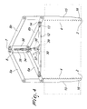
- the grab according to the present invention generally designated by the reference numeral 1, comprises four jaws, which are arranged at the corners of a quadrilateral and are connected to each other by means of an I-shaped structure.
- the structure is designated by the reference numeral 3.
- Each one of the jaws comprises an arm 2 provided with a plurality of teeth 4, which face the teeth 4 of an opposite arm 2.
- the four arms 2 are mutually connected in pairs to mutually opposite arms by means of two pairs of levers 5a, 5b and 6a, 6b.
- levers 5a and 5b are pivoted to the respective arms 2, and engage each other, i.e., the lever 5a meshes with the lever 5b thanks to the presence of complementary teeth 7 and recesses 8.
- Meshing of the levers 5a and 5b and 6a and 6b allows the levers to maintain a stable coupling when the load is lifted.
- the grab is sized so that the arms 2 grip the wire mesh packs from the inside, thus allowing to limit greatly the space occupation, so as to be able to load wire mesh packs onto a truck even if the truck does not have opening sides or in any case without having to open such sides.
- the structure 3 for connecting the arms 2 of the grab is connected, by means of a chain 10, to a ring 11 in order to lift the grab as a whole.
- a cross-member 12 connects the two levers 6a and 6b and is provided, at each of its respective ends, with a slot 13 which allows the sliding of a pivot 14 rigidly coupled to the levers 6a and 6b, so that the grab can become wider and narrower according to the sliding of the pivot 14 within the slot 13.
- Each one of the arms 2 of the grab in addition to being provided with said teeth 4, which face the teeth of the opposite arm 2, has, at the opposite side with respect to the one provided with the teeth 4, a beveled portion 15, which ends with a tapering region 16 at the lower end of the arm 2.
- This shape of the arm allows said arm to be inserted easily into one or more wire mesh packs, without having grip points which can hinder its insertion within the wire mesh pack.
- each one of the arms 2 is provided with a covering element adapted to protect the teeth as they exit.
- a device is connected to the structure 3 for mutually connecting two arms arranged so that their teeth do not face each other and is constituted by two tubular elements 20 provided with respective holes 21 and with a sleeve 22 within which the tubular element 20 slides.
- An abutment element is welded to the lower end of each tubular element and is constituted by a plate-like element 25, which is adapted to be rested against the upper surface of the lifted wire mesh pack when the arms 2 have already been lowered into the meshes of the wire mesh pack. This allows to adjust the depth of the grip of the jaws.
- tubular elements 20 like the four arms 2, which are arranged in pairs and in such a manner that two abutment elements are inserted respectively in the two mutually opposite pairs of tubular elements 20.
- the position of the abutment element can be adjusted by sliding the tubular element 20 within the sleeve 22 and by fixing the tubular element 20 by means of a rod-like pin 26, which is inserted so as to mutually connect two tubular elements 20 arranged so that their holes 21 face each other.
- the element 3 for mutually connecting two arms 2 of the structure is provided, in a downward region, with grip means for the prongs of a fork-lift truck.
- the grip means comprise two tubular elements 28, which are bolted to the connecting element 3 and are arranged externally with respect to the tubular elements 20, between such elements and each arm 2.
- tubular elements 28 lie transversely with respect to the longitudinal extension of the grab and allow the insertion of a pair of prongs so as to be able to lift the grab if a bridge crane is not available.
- a device 50 constituted by an arm arranged externally with respect to the grab according to the invention, is adapted to be arranged externally with respect to the grab so as to allow a visual indication that the grab and in particular the arms 2 have been lowered into the wire mesh pack so as to reach the selected layer of wire mesh, so as to have the assurance that said arms also grip the lowest wire mesh of the wire mesh pack to be lifted, accordingly lifting the entire pack.
- a mechanism 30 is provided for locking the levers 5a, 5b and 6a, 6b.
- the locking mechanism is constituted by a fork-like element 30, which is pivoted to the connecting element 12 which mutually connects the two levers 6a and 6b.
- the fork-like element is provided, at one of its ends, with a hook-shaped portion 31 and, at the bottom of the fork, with a protruding tooth 32.
- a plate 34 is provided for connecting the end of the four levers 5a, 5b and 6a, 6b, which mesh together by means of the teeth 7 and the recesses 8.
- Such plate 34 is provided internally with a slot 35, along which an adjustment screw 36 slides which is provided, in a downward region, with a pawl 37 which is provided with two pins 38 and 39 which are arranged at the respective ends.
- the pins 38 and 39 are adapted to engage respectively the hook-shaped portion 31 or the tooth 32 at the bottom of the fork-like element 30.
- the grab according to the invention is in the locking position and the levers 5a, 5b and 6a, 6b can no longer change their relative position, remaining open. This occurs when the grab is lowered.
- the pawl also moves downwardly and the pin 38 disengages from the hook-shaped portion 31 while the pin 39 rests against the tooth 32 arranged at the bottom of the fork-like element 30.
- the grab according to the invention operates as follows.
- the operator lifts the grab, either by means of a bridge crane or by means of a fork-lift truck, and arranges the arms 2 within the meshes of the wire mesh pack, until the indicator 40 indicates the selected depth. This is indicated by the indicator 40 provided in association with the grab according to the invention.
- the pins 26 are inserted and the grab is lowered. This entails the disengagement of the element 31 from the pin 38: in this manner, the arms 2 can close. Once the wire mesh pack has been transported to its destination, the grab is lowered and the plates 25 act as retainers on the wire mesh, while the element 31 engages the pin 38. In this manner, the arms open and can no longer close.
- the grab according to the invention fully achieves the intended aim and objects, since it allows to have a structure with compact dimensions which allows to engage the wire mesh pack from the inside, accordingly allowing to load wire mesh packs onto trucks without having to open the sides of said trucks, further being able to arrange the wire mesh packs closely adjacent to each other.
- the teeth of the arms 2 are larger at the lower end of each arm 2 and their size decreases along the extension of the arm. This prevents the arms 2, which can diverge slightly during lifting, from being unable to grip with the same force the wire mesh element that lies lowest in the pack with respect to the upper ones.
- the lower teeth grip the wire mesh pack with a larger surface than the teeth arranged higher up along the extension of the arm 2.
- the materials used may be any according to requirements and to the state of the art.
Landscapes
- Engineering & Computer Science (AREA)
- Architecture (AREA)
- Mechanical Engineering (AREA)
- Civil Engineering (AREA)
- Structural Engineering (AREA)
- Load-Engaging Elements For Cranes (AREA)
Applications Claiming Priority (1)
| Application Number | Priority Date | Filing Date | Title |
|---|---|---|---|
| IT001992A ITMI20041992A1 (it) | 2004-10-20 | 2004-10-20 | Struttura di pinza per pacchi rete, a funzionalita' migliorata. |
Publications (2)
| Publication Number | Publication Date |
|---|---|
| EP1650155A2 true EP1650155A2 (de) | 2006-04-26 |
| EP1650155A3 EP1650155A3 (de) | 2007-05-30 |
Family
ID=35589637
Family Applications (1)
| Application Number | Title | Priority Date | Filing Date |
|---|---|---|---|
| EP05022581A Withdrawn EP1650155A3 (de) | 2004-10-20 | 2005-10-17 | Greifer für gestapelte Drahtgittermatten |
Country Status (2)
| Country | Link |
|---|---|
| EP (1) | EP1650155A3 (de) |
| IT (1) | ITMI20041992A1 (de) |
Cited By (7)
| Publication number | Priority date | Publication date | Assignee | Title |
|---|---|---|---|---|
| NL1037116C2 (nl) * | 2009-07-13 | 2011-01-17 | Vlechtersbedrijf Geurts B V | Inrichting voor het verplaatsen van bewapeningsmatten. |
| NL2004719C2 (nl) * | 2010-05-13 | 2011-11-15 | Marcus Johannes Cornelis Verhoeven | Bouwstaalmat klem. |
| WO2014147650A1 (en) * | 2013-03-18 | 2014-09-25 | Thorsverk Ehf | An apparatus for mounting mats onto tunnel walls |
| NO20161065A1 (no) * | 2016-06-27 | 2017-12-28 | Anleggsupport As | Anordning og metode for montering av skumplater og armeringsnett til bruk ved tunnelbygging i fjell |
| EP3133040A4 (de) * | 2014-06-13 | 2018-01-03 | Daifuku Co., Ltd. | Behälteranhebende/-absenkende fördervorrichtung |
| BE1030494A1 (nl) | 2022-05-05 | 2023-11-29 | Levrau Nv | Inrichting en werkwijze voor het verplaatsen van één betonwapeningsnet vanuit een stapel betonwapeningsnetten |
| BE1031590A1 (nl) | 2023-05-04 | 2024-12-04 | Levrau Nv | Inrichting en werkwijze voor het verplaatsen van één betonwapeningsnet vanuit een stapel betonwapeningsnetten |
Family Cites Families (3)
| Publication number | Priority date | Publication date | Assignee | Title |
|---|---|---|---|---|
| US2399547A (en) * | 1945-04-10 | 1946-04-30 | American Mono Rail Company | Article handling device |
| DE1201961B (de) * | 1960-05-21 | 1965-09-30 | Simon Pierre | Greifzange mit Antriebsaggregat, insbesondere zum Anheben von Plattenstapeln |
| JP2833336B2 (ja) * | 1992-04-16 | 1998-12-09 | 株式会社大林組 | 格子状鉄筋の吊上げ搬送装置 |
-
2004
- 2004-10-20 IT IT001992A patent/ITMI20041992A1/it unknown
-
2005
- 2005-10-17 EP EP05022581A patent/EP1650155A3/de not_active Withdrawn
Cited By (10)
| Publication number | Priority date | Publication date | Assignee | Title |
|---|---|---|---|---|
| NL1037116C2 (nl) * | 2009-07-13 | 2011-01-17 | Vlechtersbedrijf Geurts B V | Inrichting voor het verplaatsen van bewapeningsmatten. |
| WO2011008080A1 (en) * | 2009-07-13 | 2011-01-20 | Vlechtersbedrijf Geurts | Device for moving reinforcing mats |
| NL2004719C2 (nl) * | 2010-05-13 | 2011-11-15 | Marcus Johannes Cornelis Verhoeven | Bouwstaalmat klem. |
| WO2011142659A1 (en) | 2010-05-13 | 2011-11-17 | Marcus Johannes Cornelis Verhoeven | Reinforcing steel mat clamp |
| WO2014147650A1 (en) * | 2013-03-18 | 2014-09-25 | Thorsverk Ehf | An apparatus for mounting mats onto tunnel walls |
| EP3133040A4 (de) * | 2014-06-13 | 2018-01-03 | Daifuku Co., Ltd. | Behälteranhebende/-absenkende fördervorrichtung |
| NO20161065A1 (no) * | 2016-06-27 | 2017-12-28 | Anleggsupport As | Anordning og metode for montering av skumplater og armeringsnett til bruk ved tunnelbygging i fjell |
| NO343085B1 (no) * | 2016-06-27 | 2018-10-29 | Anleggsupport As | Anordning og metode for montering av skumplater og armeringsnett til bruk ved tunnelbygging i fjell |
| BE1030494A1 (nl) | 2022-05-05 | 2023-11-29 | Levrau Nv | Inrichting en werkwijze voor het verplaatsen van één betonwapeningsnet vanuit een stapel betonwapeningsnetten |
| BE1031590A1 (nl) | 2023-05-04 | 2024-12-04 | Levrau Nv | Inrichting en werkwijze voor het verplaatsen van één betonwapeningsnet vanuit een stapel betonwapeningsnetten |
Also Published As
| Publication number | Publication date |
|---|---|
| ITMI20041992A1 (it) | 2005-01-20 |
| EP1650155A3 (de) | 2007-05-30 |
Similar Documents
| Publication | Publication Date | Title |
|---|---|---|
| US7544037B2 (en) | Pallet clamping device | |
| EP1650155A2 (de) | Greifer für gestapelte Drahtgittermatten | |
| US3050206A (en) | Load handling system | |
| US5011360A (en) | Self-emptying container | |
| US4000923A (en) | Gabion basket emplacement apparatus and method | |
| US2902311A (en) | Tubular loading mechanism | |
| US7278669B2 (en) | Bottom discharge container | |
| US6086316A (en) | Container handling assembly | |
| FR2531043A1 (fr) | Pupitre de stockage et de transport pour des piles de carreaux de verre de grandes dimensions | |
| FI77829B (fi) | Stockhanteringsanordning. | |
| JPH07315785A (ja) | 鞘フォーク及びフォークリフト | |
| JP3321145B2 (ja) | 底開き式コンテナ | |
| KR102087903B1 (ko) | 건설자재 인양박스 | |
| JP3889215B2 (ja) | ローダ | |
| US3252729A (en) | Sling carrier | |
| US2224913A (en) | Material handling apparatus | |
| US20020187033A1 (en) | Drum handling device | |
| KR200353657Y1 (ko) | 웨이퍼 이송 보트 파지용 로봇 아암 | |
| JP4935265B2 (ja) | 板状体の輸送用パレット | |
| CA2633160C (en) | Bale handling apparatus and method | |
| EP0107326A1 (de) | Ladeverfahren für eine Wechselplattform, Ladeeinrichtung und Wechselplattform | |
| JP7825845B1 (ja) | 積載物の持上げ器、同装置及び挿入補助具を備えた持上げ組み装置、それらを用いた方法 | |
| JP2715170B2 (ja) | フォークリフトのプッシュプル装置 | |
| JP4644454B2 (ja) | コンテナ | |
| JP2024140501A (ja) | トング装置 |
Legal Events
| Date | Code | Title | Description |
|---|---|---|---|
| PUAI | Public reference made under article 153(3) epc to a published international application that has entered the european phase |
Free format text: ORIGINAL CODE: 0009012 |
|
| AK | Designated contracting states |
Kind code of ref document: A2 Designated state(s): AT BE BG CH CY CZ DE DK EE ES FI FR GB GR HU IE IS IT LI LT LU LV MC NL PL PT RO SE SI SK TR |
|
| AX | Request for extension of the european patent |
Extension state: AL BA HR MK YU |
|
| RIC1 | Information provided on ipc code assigned before grant |
Ipc: B66C 1/36 20060101ALI20070124BHEP Ipc: B66C 1/44 20060101ALI20070124BHEP Ipc: B66C 1/42 20060101AFI20070124BHEP |
|
| PUAL | Search report despatched |
Free format text: ORIGINAL CODE: 0009013 |
|
| AK | Designated contracting states |
Kind code of ref document: A3 Designated state(s): AT BE BG CH CY CZ DE DK EE ES FI FR GB GR HU IE IS IT LI LT LU LV MC NL PL PT RO SE SI SK TR |
|
| AX | Request for extension of the european patent |
Extension state: AL BA HR MK YU |
|
| AKX | Designation fees paid | ||
| REG | Reference to a national code |
Ref country code: DE Ref legal event code: 8566 |
|
| STAA | Information on the status of an ep patent application or granted ep patent |
Free format text: STATUS: THE APPLICATION IS DEEMED TO BE WITHDRAWN |
|
| 18D | Application deemed to be withdrawn |
Effective date: 20071201 |