EP1652200B1 - Systeme de condensateur a circulation continue a bon rendement energetique - Google Patents
Systeme de condensateur a circulation continue a bon rendement energetique Download PDFInfo
- Publication number
- EP1652200B1 EP1652200B1 EP04780421A EP04780421A EP1652200B1 EP 1652200 B1 EP1652200 B1 EP 1652200B1 EP 04780421 A EP04780421 A EP 04780421A EP 04780421 A EP04780421 A EP 04780421A EP 1652200 B1 EP1652200 B1 EP 1652200B1
- Authority
- EP
- European Patent Office
- Prior art keywords
- flow
- cells
- capacitor
- capacitor system
- power
- Prior art date
- Legal status (The legal status is an assumption and is not a legal conclusion. Google has not performed a legal analysis and makes no representation as to the accuracy of the status listed.)
- Expired - Lifetime
Links
- 239000003990 capacitor Substances 0.000 title claims description 149
- 238000000746 purification Methods 0.000 claims description 35
- XLYOFNOQVPJJNP-UHFFFAOYSA-N water Chemical compound O XLYOFNOQVPJJNP-UHFFFAOYSA-N 0.000 claims description 26
- 239000000463 material Substances 0.000 claims description 20
- 238000000034 method Methods 0.000 claims description 19
- 239000012530 fluid Substances 0.000 claims description 18
- 125000006850 spacer group Chemical group 0.000 claims description 10
- 230000001960 triggered effect Effects 0.000 claims description 6
- 239000002699 waste material Substances 0.000 claims description 6
- 230000000712 assembly Effects 0.000 claims description 5
- 238000000429 assembly Methods 0.000 claims description 5
- 239000008213 purified water Substances 0.000 claims description 5
- 239000012264 purified product Substances 0.000 claims description 3
- 238000011084 recovery Methods 0.000 claims description 3
- 230000001360 synchronised effect Effects 0.000 claims description 3
- 239000000446 fuel Substances 0.000 claims description 2
- OKTJSMMVPCPJKN-UHFFFAOYSA-N Carbon Chemical compound [C] OKTJSMMVPCPJKN-UHFFFAOYSA-N 0.000 description 11
- 230000004888 barrier function Effects 0.000 description 11
- 229910052751 metal Inorganic materials 0.000 description 11
- 239000002184 metal Substances 0.000 description 11
- 229910002804 graphite Inorganic materials 0.000 description 7
- 239000010439 graphite Substances 0.000 description 7
- 238000004587 chromatography analysis Methods 0.000 description 6
- 238000013461 design Methods 0.000 description 6
- 229920000642 polymer Polymers 0.000 description 6
- 238000002156 mixing Methods 0.000 description 5
- 239000011230 binding agent Substances 0.000 description 4
- 229910052799 carbon Inorganic materials 0.000 description 4
- 238000009826 distribution Methods 0.000 description 4
- 239000007772 electrode material Substances 0.000 description 4
- 239000000017 hydrogel Substances 0.000 description 4
- 239000007788 liquid Substances 0.000 description 4
- 239000011159 matrix material Substances 0.000 description 4
- 239000000243 solution Substances 0.000 description 4
- GWEVSGVZZGPLCZ-UHFFFAOYSA-N Titan oxide Chemical compound O=[Ti]=O GWEVSGVZZGPLCZ-UHFFFAOYSA-N 0.000 description 3
- 239000000654 additive Substances 0.000 description 3
- 230000000996 additive effect Effects 0.000 description 3
- 230000006835 compression Effects 0.000 description 3
- 238000007906 compression Methods 0.000 description 3
- 239000011888 foil Substances 0.000 description 3
- 239000002071 nanotube Substances 0.000 description 3
- 239000002245 particle Substances 0.000 description 3
- 239000013535 sea water Substances 0.000 description 3
- 239000007787 solid Substances 0.000 description 3
- 238000011144 upstream manufacturing Methods 0.000 description 3
- KDLHZDBZIXYQEI-UHFFFAOYSA-N Palladium Chemical compound [Pd] KDLHZDBZIXYQEI-UHFFFAOYSA-N 0.000 description 2
- 239000006229 carbon black Substances 0.000 description 2
- 239000000919 ceramic Substances 0.000 description 2
- 229920001940 conductive polymer Polymers 0.000 description 2
- 230000000694 effects Effects 0.000 description 2
- 150000002500 ions Chemical class 0.000 description 2
- 238000002955 isolation Methods 0.000 description 2
- 239000004816 latex Substances 0.000 description 2
- 229920000126 latex Polymers 0.000 description 2
- 238000004519 manufacturing process Methods 0.000 description 2
- 239000012528 membrane Substances 0.000 description 2
- 150000002739 metals Chemical class 0.000 description 2
- 239000000203 mixture Substances 0.000 description 2
- BASFCYQUMIYNBI-UHFFFAOYSA-N platinum Chemical compound [Pt] BASFCYQUMIYNBI-UHFFFAOYSA-N 0.000 description 2
- -1 polypropylene Polymers 0.000 description 2
- 239000000843 powder Substances 0.000 description 2
- 238000000926 separation method Methods 0.000 description 2
- 229920001169 thermoplastic Polymers 0.000 description 2
- 239000004416 thermosoftening plastic Substances 0.000 description 2
- OGIDPMRJRNCKJF-UHFFFAOYSA-N titanium oxide Inorganic materials [Ti]=O OGIDPMRJRNCKJF-UHFFFAOYSA-N 0.000 description 2
- 229920000049 Carbon (fiber) Polymers 0.000 description 1
- 239000004215 Carbon black (E152) Substances 0.000 description 1
- YCKRFDGAMUMZLT-UHFFFAOYSA-N Fluorine atom Chemical compound [F] YCKRFDGAMUMZLT-UHFFFAOYSA-N 0.000 description 1
- 239000004743 Polypropylene Substances 0.000 description 1
- RTAQQCXQSZGOHL-UHFFFAOYSA-N Titanium Chemical compound [Ti] RTAQQCXQSZGOHL-UHFFFAOYSA-N 0.000 description 1
- 238000010521 absorption reaction Methods 0.000 description 1
- 239000002253 acid Substances 0.000 description 1
- 239000000853 adhesive Substances 0.000 description 1
- 230000001070 adhesive effect Effects 0.000 description 1
- 239000004964 aerogel Substances 0.000 description 1
- 150000001336 alkenes Chemical class 0.000 description 1
- 238000013459 approach Methods 0.000 description 1
- 239000004917 carbon fiber Substances 0.000 description 1
- 230000022131 cell cycle Effects 0.000 description 1
- 239000011248 coating agent Substances 0.000 description 1
- 238000000576 coating method Methods 0.000 description 1
- 239000002131 composite material Substances 0.000 description 1
- 239000011530 conductive current collector Substances 0.000 description 1
- 239000004020 conductor Substances 0.000 description 1
- 239000000356 contaminant Substances 0.000 description 1
- 229920006037 cross link polymer Polymers 0.000 description 1
- 238000005520 cutting process Methods 0.000 description 1
- 230000007423 decrease Effects 0.000 description 1
- 238000002242 deionisation method Methods 0.000 description 1
- 238000010612 desalination reaction Methods 0.000 description 1
- 238000007599 discharging Methods 0.000 description 1
- 238000004821 distillation Methods 0.000 description 1
- 238000004146 energy storage Methods 0.000 description 1
- 239000012527 feed solution Substances 0.000 description 1
- 230000005669 field effect Effects 0.000 description 1
- 229910052731 fluorine Inorganic materials 0.000 description 1
- 239000011737 fluorine Substances 0.000 description 1
- NBVXSUQYWXRMNV-UHFFFAOYSA-N fluoromethane Chemical compound FC NBVXSUQYWXRMNV-UHFFFAOYSA-N 0.000 description 1
- 239000004811 fluoropolymer Substances 0.000 description 1
- 229920002313 fluoropolymer Polymers 0.000 description 1
- 239000000499 gel Substances 0.000 description 1
- 239000007770 graphite material Substances 0.000 description 1
- 229930195733 hydrocarbon Natural products 0.000 description 1
- 150000002430 hydrocarbons Chemical class 0.000 description 1
- 239000012212 insulator Substances 0.000 description 1
- 239000003014 ion exchange membrane Substances 0.000 description 1
- 229920003303 ion-exchange polymer Polymers 0.000 description 1
- 229920000554 ionomer Polymers 0.000 description 1
- 238000003475 lamination Methods 0.000 description 1
- 230000002045 lasting effect Effects 0.000 description 1
- 238000005259 measurement Methods 0.000 description 1
- 238000012544 monitoring process Methods 0.000 description 1
- JRZJOMJEPLMPRA-UHFFFAOYSA-N olefin Natural products CCCCCCCC=C JRZJOMJEPLMPRA-UHFFFAOYSA-N 0.000 description 1
- 229910052763 palladium Inorganic materials 0.000 description 1
- 229910052697 platinum Inorganic materials 0.000 description 1
- 229920001155 polypropylene Polymers 0.000 description 1
- 239000004810 polytetrafluoroethylene Substances 0.000 description 1
- 229920001343 polytetrafluoroethylene Polymers 0.000 description 1
- 239000011148 porous material Substances 0.000 description 1
- 230000000750 progressive effect Effects 0.000 description 1
- 230000002441 reversible effect Effects 0.000 description 1
- 150000003839 salts Chemical class 0.000 description 1
- 238000003892 spreading Methods 0.000 description 1
- 229910052715 tantalum Inorganic materials 0.000 description 1
- GUVRBAGPIYLISA-UHFFFAOYSA-N tantalum atom Chemical compound [Ta] GUVRBAGPIYLISA-UHFFFAOYSA-N 0.000 description 1
- 239000010936 titanium Substances 0.000 description 1
- 229910052719 titanium Inorganic materials 0.000 description 1
- 125000000391 vinyl group Chemical group [H]C([*])=C([H])[H] 0.000 description 1
- 229920002554 vinyl polymer Polymers 0.000 description 1
Images


Classifications
-
- C—CHEMISTRY; METALLURGY
- C02—TREATMENT OF WATER, WASTE WATER, SEWAGE, OR SLUDGE
- C02F—TREATMENT OF WATER, WASTE WATER, SEWAGE, OR SLUDGE
- C02F1/00—Treatment of water, waste water, or sewage
- C02F1/46—Treatment of water, waste water, or sewage by electrochemical methods
- C02F1/469—Treatment of water, waste water, or sewage by electrochemical methods by electrochemical separation, e.g. by electro-osmosis, electrodialysis, electrophoresis
- C02F1/4691—Capacitive deionisation
-
- C—CHEMISTRY; METALLURGY
- C02—TREATMENT OF WATER, WASTE WATER, SEWAGE, OR SLUDGE
- C02F—TREATMENT OF WATER, WASTE WATER, SEWAGE, OR SLUDGE
- C02F1/00—Treatment of water, waste water, or sewage
- C02F1/46—Treatment of water, waste water, or sewage by electrochemical methods
- C02F1/4604—Treatment of water, waste water, or sewage by electrochemical methods for desalination of seawater or brackish water
-
- C—CHEMISTRY; METALLURGY
- C02—TREATMENT OF WATER, WASTE WATER, SEWAGE, OR SLUDGE
- C02F—TREATMENT OF WATER, WASTE WATER, SEWAGE, OR SLUDGE
- C02F1/00—Treatment of water, waste water, or sewage
- C02F1/46—Treatment of water, waste water, or sewage by electrochemical methods
- C02F1/461—Treatment of water, waste water, or sewage by electrochemical methods by electrolysis
- C02F1/46104—Devices therefor; Their operating or servicing
- C02F1/46109—Electrodes
- C02F2001/46152—Electrodes characterised by the shape or form
-
- C—CHEMISTRY; METALLURGY
- C02—TREATMENT OF WATER, WASTE WATER, SEWAGE, OR SLUDGE
- C02F—TREATMENT OF WATER, WASTE WATER, SEWAGE, OR SLUDGE
- C02F2103/00—Nature of the water, waste water, sewage or sludge to be treated
- C02F2103/08—Seawater, e.g. for desalination
-
- C—CHEMISTRY; METALLURGY
- C02—TREATMENT OF WATER, WASTE WATER, SEWAGE, OR SLUDGE
- C02F—TREATMENT OF WATER, WASTE WATER, SEWAGE, OR SLUDGE
- C02F2201/00—Apparatus for treatment of water, waste water or sewage
- C02F2201/46—Apparatus for electrochemical processes
- C02F2201/461—Electrolysis apparatus
- C02F2201/46105—Details relating to the electrolytic devices
- C02F2201/4611—Fluid flow
-
- C—CHEMISTRY; METALLURGY
- C02—TREATMENT OF WATER, WASTE WATER, SEWAGE, OR SLUDGE
- C02F—TREATMENT OF WATER, WASTE WATER, SEWAGE, OR SLUDGE
- C02F2201/00—Apparatus for treatment of water, waste water or sewage
- C02F2201/46—Apparatus for electrochemical processes
- C02F2201/461—Electrolysis apparatus
- C02F2201/46105—Details relating to the electrolytic devices
- C02F2201/4612—Controlling or monitoring
- C02F2201/46125—Electrical variables
- C02F2201/4613—Inversing polarity
-
- C—CHEMISTRY; METALLURGY
- C02—TREATMENT OF WATER, WASTE WATER, SEWAGE, OR SLUDGE
- C02F—TREATMENT OF WATER, WASTE WATER, SEWAGE, OR SLUDGE
- C02F2201/00—Apparatus for treatment of water, waste water or sewage
- C02F2201/46—Apparatus for electrochemical processes
- C02F2201/461—Electrolysis apparatus
- C02F2201/46105—Details relating to the electrolytic devices
- C02F2201/4612—Controlling or monitoring
- C02F2201/4615—Time
-
- C—CHEMISTRY; METALLURGY
- C02—TREATMENT OF WATER, WASTE WATER, SEWAGE, OR SLUDGE
- C02F—TREATMENT OF WATER, WASTE WATER, SEWAGE, OR SLUDGE
- C02F2209/00—Controlling or monitoring parameters in water treatment
- C02F2209/005—Processes using a programmable logic controller [PLC]
Definitions
- the field of the invention is systems for capacitive deionization of fluids by the use of flow through capacitors.
- Power efficiency is a measure of how well power is distributed in a multi-cell system, and is defined here as the averaged percent of power needed by a flow-through capacitor system divided by the system's peak power needs.
- Staging efficiency is a measure of how well a staged system is designed to limit the inter-stage mixing caused by inter-stage dead volume, and is defined here as the percent purification achieved by a multi-cell or multi-stage system divided by the sum of the percent purifications of each individual cell or stage.
- each cell or stage of a flow-through capacitor system has been housed within a separate housing or cartridge holders, which were charged or discharged together, either in parallel or in series. See, e.g., US 2004/0121204 A1 .
- a dead volume mixes with the water which is purified in each stage, and decreases the resolution of the band of purified water, due to band broadening, as it moves from one stage to another.
- the mixing effect also leads to a need to operate with greater numbers of stages, and may reach a lower voltage limit, as voltage is lowered when used with concentrated water such as sea water.
- a need exists for an improved flow-through capacitor which has less mixing of purifed or concentrated water with each other or with the feed water, and for a method and system which allows the capacitor to operate more efficiently at lower, energy saving voltages.
- capacitors exhibit a charging characteristic whereby upon initial application of a voltage, they require peak power. Charging banks or stages of capacitors all at once multiplies this peak power, thereby increasing the wattage rating and cost of power supplies needed to provide this power. Therefore, an additional need exists to more efficiently distribute power to banks of flow-through capacitor cells which may be fluid or electrically staged in a combination of parallel or in series.
- WO0195410 discloses a flow-through electrochemical system which includes a plurality of flow-through electrochemical cells, the system configured to place each of the cells in electrical connection and in fluid connection with each of the other cells.
- the system includes a fluid stream, a means for connecting the system to a power supply, a means for monitoring the voltage of each of a plurality of cells and a means for controlling the voltage of each of the plurality of cells.
- Sequentially powered and controlled flow-through capacitor systems of the present invention control individual flow-through capacitor cells, or groups of cells, in a timed sequence, with individual cells out of phase with each other.
- the system of the present invention may be configured with one cell per cartridge holder.
- the flow-through capacitor system is configures to have one or more integrated stages, by which is meant that two more purification stages occupy a common housing, i.e., are within the same container or cartridge holder.
- integral staging is achieved by housing two or more flow-through capacitor cells within a single container or cartridge holder.
- the integrated stage design embodiment of the present invention eliminates the need, cost, and complication of connecting separate cartridge holders per stage by containing multiple stages within the same cartridge holder.
- This integrated stage design reduces the band broadening that would otherwise be caused by mixing of the band of purified water with dead volume as it moves from stage to stage. Staging efficiencies of 50% or more are possible by using sequential charge cycles coupled with integrated stage design.
- Another advantage achieved by organizing a flow-through capacitor system so that some or all stages are physically integrated is to diminish the amount of dead volume that otherwise exists between the capacitor layers and the inside the walls of the cartridge holder or capacitor container.
- the integrated stage design of the present invention incrementally sharpens purified and concentrated bands of feed solution as it flows from stage to stage.
- a dead volume exists between each multilayer capacitor cell and the internal walls of the housing of the cartridge holder.
- each stage shares common capacitor material layers. Only the current collectors, or, where electrodes are conductive enough not to need a current collector, the electrodes, are independently actuated and electrically separated from each other. Therefore, multiple stages can share the same cartridge holder, thereby eliminating the need for separate current collectors. Eliminating excess dead volume through integrated staging allows operation of the capacitor at lower voltage while, at the same time, obtaining a deep purification peak. The result of this is that the capacitor may be operated at lower, more energy efficient voltages.
- One special use of integrated staging is for low energy desalination of sea water.
- the present invention achieves that end by removing a little bit of salt at a time at low energy, and then amplifying this signal by virtue of synchronous charging of multiple capacitor stages that share the same capacitive material, spacer, and optional charge barrier layers in order to sharpen bands of purified and concentrated water.
- This band sharpening method uses staging to refine or sharpen concentration bands, analogous to other staged methods such as chromatography, distillation, and absorption.
- An additional advantage of the sequential charging system of the present invention is to provide power in steps between multiple cells in order to optimize peak power usage to allow use of lower wattage, less expensive power supplies, so as to avoid the requirement for peak power at the initial application of voltage and distribute power to banks, or stages, of flow-through capacitor cells which may be fluid or electrically staged in a combination of parallel or in series.
- the flow-through capacitor of the present invention can make use of the same layers used in prior flow-through capacitors systems, such as, for example, US 6,413,409 and US 6,709560 ("Charge barrier flow-through Capacitor").
- a flow-through capacitor system of the present invention in place of integral current collectors backing one or more electrode layers, multiple current collectors are arranged sequentially along a fluid flow path. In the integrated stage embodiment, these are arrayed within the same cartridge holder. These current collectors are made to be charged or discharged according to various sequences and times. The sequential charging of the multiple current collectors may either be done in series or in parallel, and in addition, within the context of either a series or a parallel flow cell.
- Load leveling may be achieved by such sequential control of flow-through capacitors cells according to the present invention whereby capacitor cells are charged or discharged in a timed sequence. In doing so, the present invention avoids the multiplication of peak power needs, thereby minimizing the size and cost of power supplies required to power a multiple flow-through capacitor system.
- the cells may be progressively powered or charged in parallel, or in series. If powered or charged in series, the voltage is stepped up as each cell is switched in an additive sequence onto the others in series.
- Parallel cells may be powered or charged by switching onto a common bus. Individual cells may have individual or common power supplies.
- Flow-through capacitor cells can be integrated within a single cartridge holder, or may be discrete cells in a combination of series or parallel electrical or fluid flow.
- Upstream cells within an integrated stage cartridge holder, or individual stages with one cell per cartridge holder, or groups of cells, may be charged first, then additional downstream stages or cells are charged with a time delay.
- Cells connected together, either singly or in groups, in parallel or series in an electrical or fluid flow sense, may be sequentially actuated or controlled according to the present invention. This time delay may be selected so that the peak capacitive charging peaks do not overlap, in order to obtain a lower average peak charging current.
- charge cycles of individual cells or groups of cells are preferably actuated sequentially, or between 1 and 359 degrees out of phase, such as by charging or discharging, or reversing the cell polarities in increments that vary between one and one hundred seconds. For example, cells can be charged or discharged in increments of between five and thirty seconds. Sequential operation of the charge cycles may also follow other patterns than the direction of flow. For example, where it is important to quickly reduce the output conductivity, it may be preferable to charge the downstream cells first.
- a voltage or an amperage sensor may relay data from individual cells to a logic chip or circuit in order to control the sequence of actuation of a series of flow-through capacitor cells or groups of cells.
- the circuits used to distribute power to flow-through capacitor system preferably provide DC power in a sequential fashion in order to minimize the capacitive charging power surge.
- Circuits designed for stepwise charging of multiple batteries, multiplex charging or discharge of banks of batteries may be used to distribute power to the flow-through capacitor cells according to the present invention; examples of such circuit design include, without limitation, US 6140799 , US 6326768 , US 6140799 , US6750631 , US 5506456 , US 5461264 , US 5483643 , US 5514480 , and US 5710504 .
- Examples of a power sequencer circuit include, but are not limited to, US 6766222 and US 6239510 , circuits used in solar power distribution such as US 6685334 where the solar power source is replaced by a DC power source, power distribution circuits where DC power is provided or substituted for AC outputs and used to provide sequential power control according to the present invention.
- a timer circuit that may be used for sequential control of flow-through capacitor cells according to the present invention is described in US 6011329 .
- FETS Power Field Effect Transistors
- thyristors may be also used as mechanical contacts or relays in various timer circuits that may be employed, for one example, an H Bridge FET circuits such as described by Blanchard, Eugene (http://www.armory.com/-rstevew/Public/Motors/H-Bridges/Blanchard/h-bridge.htm; last visited August 6, 2004).
- Power may be distributed to multiple stages of the present invention by using a power distribution or power management system circuits designed to control peak loads, or a sequential power distribution circuit.
- Useful examples of circuits that may be used, where the electric loads are multiple flow-through capacitor cells include without limitation US 5119014 , US 4093943 , US 4180744 , US RE29560 , US 6385057 , US 5070440 , US 5969435 , and US 4894764 .
- power sharing schemes where batteries, fuel cells, or generators are used to receive or give power to or from either the flow-through capacitor system of the invention or a prior art flow-through capacitor system may also be used.
- a sequential power circuit similar to ones used to generate current pulses including but not limited to US 4001598 , US 5952735 , and US 5585758 can also be used to sequentially charge and discharge flow-through capacitor loads to a power source in order to offset by between 1 and 100 seconds the peak amp and power requirements of individual flow-through capacitor cells in a multiple cell system. Failed or short circuited cells may be bypassed by using a current or voltage sensing or voltage drop circuit such as without limitation US 6087035 , US 5362576 , and US5650240 to close valves into or out of individual cells.
- another way to cut peak power needs is to use charged capacitors to power discharged capacitors, using an optional DC to DC converter between cells or series groups of cells to save additional energy if desired.
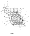
- Fig. 1 is a schematic of an integrated stage flow-through capacitor cell and system of the present invention, showing a controller or logic means 1, a power supply 2, e.g., a capacitor power supply, a switch power supply 3, ground 4, switches, relays, or FETS, e.g., switches 5, a cartridge or cell holder 6 as a casing for one or more capacitor cells, inlet 7, electrode or electrode assembly 8, outlet 9, flow path 10, individual current collector 11, individual current collector lead 12, circuit 13, e.g., an integrated circuit, programmable logic chip, digital input/out, or printed circuit; cell assembly 14, and sensor 15.
- a power supply 2 e.g., a capacitor power supply
- a switch power supply 3 ground 4
- switches, relays, or FETS e.g., switches 5
- a cartridge or cell holder 6 as a casing for one or more capacitor cells, inlet 7, electrode or electrode assembly 8, outlet 9, flow path 10, individual current collector 11, individual current collector lead 12, circuit 13, e.g., an integrated circuit,
- a computer or controller 1 and a additional digital input/output 13 controls and actuates switches, relays, or FETS 5 in either a preprogrammed or feed-back controlled sequence using conductivity, pH, or other composition data, or flow, amperage, or voltage data supplied to controller 1 by sensor 15.
- Switch 5 can be multiple switching, and can also be an integrated circuit or chip with multiple outputs, can be triggered to ground 4 and thereby allow flow of current to current collector leads 12 into individual current collectors 11.
- Cell assembly 14 is made of electrode or electrode assembly layers 8 with flow spacer or spacers 16 (shown in Fig. 2 ), and individual current collectors 11.
- Multiple switching 5 can be controlled by a programmable chip, computer, controller, logic, timer, or in response to amp, voltage, or conductivity sensor data input, to sequentially charge or power the individual collector leads 12.
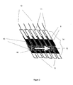
- Fig. 2 represents a detailed view of a flow-through capacitor cell assembly 14 of the present invention showing optional electrical insulating spacers 15, insulating electrodes or electrode assemblies 8 one from the other. Electrode assemblies 8 are backed by individual current collectors 11 which are individually connected to individually actuated electrical leads 12.
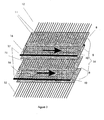
- Fig. 3 represents an integrated stage flow-through capacitor cell of the present invention with individual current collectors 11, current collector leads 12, against electronically conducting electrode or electrode assembly 8.
- the electrode or electrode assembly 8 is spaced apart by flow space or flow spacer 16 with optional flow or series electrical isolation gaskets 14.
- Flow path 10 is shown cutting across the multiple current collectors 11 connected to individual electrical leads 12.
- the multiple current collectors shown in Fig. 3 may be thin enough to be wires, for example, less than two millimeters in diameter.
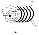
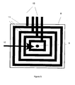
- Fig. 4 represents a spiral or concentric flow-through capacitor of the present invention with electrodes or electrode assembly 8, flow path 10 intercepting multiple current collectors 11 connected to individual electrical leads 12.
- Fig. 5 represents a nested integrated stage flow-through capacitor single electrode assembly layer 8 with associated individual current collectors 11 and current collector leads 12, flow path 10 and flow inlet our outlet.
- Fig. 6 represents a flow-through capacitor of the present invention with a matrix series connection such that individual cells may be connected in series both horizontally and vertically.
- Fig. 6 illustrates cartridge holder or capacitor casing 6, inlet or outlet 7, outlet or inlet 9, current collectors 11, individual current collector leads 12, and series separator 18, and high resistive series cell separator flow path 10. Only individual current collectors 11 and current collector leads 12 are shown, with the addition of inter-cell series separators 18. An optional high resistive flow path 19 is included for use when current collectors 11 are connected in series across the stack. Either a parallel or a series cell, not shown, would be placed between the end current collectors 11.
- Cartridge holder or capacitor casing 6 contains the matrix connected flow-through capacitor formed by these components plus additional electrodes or electrode assembly layers 8 and flow spacers 16 shown in Fig. 2
- Fig. 7 represents a flow-through capacitor of the present invention with the flow parallel to the current collector 11, which may be used to provide continuous concentration streams 20 and purified solution flow channel 21 to provide a purification stream.
- Concentration stream 22 is a flow channel for concentrated solution.
- Purification stream 23 is a flow channel for purified solution. Concentration stream 22 and purification stream 23 are connected by manifolds so as to combine together the concentration streams 20 and purification streams 21 produced by multiple electrode or electrode assembly layers 8.
- curves I1 through I8 represent eight separate charging currents of eight flow-through capacitor cells sequentially charged at constant voltage in an eight cell integrally staged flow-through capacitor system.
- constant current schemes can also be used. This charging scheme can be applied to either integrated or individual flow-through capacitor cells. Notice how each current trace, I 1 through I 8, has a typical capacitive charging shape, with peak current in the time equals less than one seconds, then leveling off rapidly after that over a period of 1 to 60 seconds or more. If, for example, the multiple cells have been charged together in parallel or in series, there would only have been one charging curve with a maximized peak wattage. This is undesirable because it requires a larger, more expensive power supply.
- the additive power is reduced.
- the additive power can be averaged over multiple cells in this way, to comprise the average power usage over a charge cycle averaged over a number of cells.
- the charge cycles can be synchronized to correspond with the arrival of a traveling purification segment or peak as it moves serially from cell to cell, in order to trigger progressive removal of total dissolved solids from that purification peak.
- Flow can also be parallel through a number of cells with asynchronous charge cycles.
- a charge cycle may be a combination of constant voltage, constant current, reverse polarity, and optional shunt cycles, with each such portion of a charge cycle lasting between zero and 300 seconds or more, for example 60 seconds, or 5000 seconds.
- Charge cycles between individual flow-through capacitor cells may be asynchronous or out of phase between one quarter and 300 seconds or more, for example, 100 seconds or 10,000 seconds.
- Charge cycles may be triggered by a timer, a conductivity reading, a voltage, a pH, or other data.
- Valves to individual cells or groups of cells that dispose of waste, delivered purified fluid, or which recycle in flow loops may be triggered synchronously or asynchronously together with the above charge cycles. For example, it may be desirable to trigger individual valves from individual cells in a multi-cell system at the same time the purification or waste part of a charge cycle is triggered.
- the purified product or concentrated waste segments of water from individual cells or cell groups may subsequently be combined together, such as through a manifold, in order to maximize the level of purification or concentration, for example, to than 40% purified and better than 40% recovery or more, for example 90%.
- the integrated stage flow-through capacitor of the present invention utilizes multiple current collectors 11 individually connected to current collector leads 12 with common flow path layers 14, and electrode or electrode assembly layers 8 that may be optionally separated by inter electrode insulators 19.
- the current collectors are multiple in the sense that a plurality of current collectors are transected by a common flow path 10, share common electrode or electrode assemblies 8, or are placed within the same cartridge holder or capacitor casing 6.
- a stage is represented by a pair of current collectors typically perpendicular to, but optionally parallel to, the flow path 10. Flow path 10 therefore typically intersects oppositely charge current collector pairs. As the fluid in flow path 10 flows across these current collector pairs, the current collectors, through individual current collector leads 12, are activated in a sequence.
- This sequence can either be programmed or may be trigged by a sensor 17.
- a sensor 17 Each time a pair of current collectors is activated with a voltage, additional materials are either removed from or added to a band of water which flows from cell to cell, where cell may be defined as a oppositely charged pair of current collectors charged together in time as part of a charge sequence among many pairs of current collectors.
- the multiple current collectors 11 of the present invention within each cartridge holder may bracket a stack of electrode assemblies 8 that are electrically insulated from each other in true series fashion, such as in US 6628505 or the current collectors can be bundled together in parallel, to form anode and cathode, with geometries as known to those skilled in the art, including but not limited to the geometries of US 5,192,432 , "Flow Through Capacitor "; US 5,196,115 , “Controlled Charge Chromatography System”; US 5,200,068 , “Controlled Charge Chromatography System”; US 5,360,540 , “Chromatography System”; US 5,415,768 , “Flow-Through Capacitor "; US 5,538,611 , "Planar, Flow-Through, Electric.
- Double Layer Capacitor And A Method Of Treating Liquids With The Capacitor US 5,547,581 , “Method Of separating Ionic Fluids With A Flow Through Capacitor "; US 5,620,597 , “Non-Fouling Flow-Through Capacitor”; US 5,748,437 , “Fluid Separation System With Flow-Through Capacitor”; US 5,779,891 , “Non-Fouling Flow-Through Capacitor System”; US 6,127,474 , “Strengthened Conductive Polymer Stabilized Electrode Composition And Method of Preparing "; US 6,325,907 , “Energy And Weight Efficient Flow-Through Capacitor, System And Method”; US 6,413,409 , “Flow-Through Capacitor And Method Of Treating Liquids With It.
- the electrode assembly 8 can include a combination flow-through capacitor electrodes and optional current collector, ion perm selective membranes, or charge barrier material.
- the electrode can be comprised of high capacitance particles, including carbon or ceramics, held together with a binder material including a hydrogel or functional charge barrier material, fibrillated polypropylene or PTFE, latex, or cross linked or sintered polymer or hydrocarbon materials.
- a charge barrier material may be a fluorine containing ionomer, an elastomeric or thermoformable hydrogel containing either or both of strong acid or strong base functionality. Materials of use as charge barriers are known to those skilled in the art. ( See, e.g., Toshikatsu Sata, Ion Exchange Membranes, The Royal Society of Chemistry, publ., 2004 ).
- An important aspect of the invention is the ability to vary the voltage, current, or power, either perpendicular or parallel to the flow path within a single cartridge holder, or among a group of single cartridge holder cells.
- this is accomplished by incorporating multiple current collectors within a single cartridge holder, where the current collectors can have individual electrode, charge barrier, and flow spacer layers, or can share one or more of these layers in order to simplify manufacture.
- a fluid, solution, or solute to be purified of concentrated is introduced into each cell. As this fluid flows through each cell, the multiple current collectors are independently synchronously actuated with a purification or a concentration peak that forms as the flow moves through each cell. This is analogous to the peaks formed in chromatography systems.
- a small amount of total dissolved solids can be purified from water each time the flow stream passes a particular current collector, or pair, or set of current collectors. This produces a slightly purified aliquot of water. As this aliquot moves along its flow path, additional current collectors are actuated. Where this flow path cuts across multiple current collectors, the flow stream is separated into purification and concentration peaks that can be separated, e.g., by a valve. Where the flow is parallel to the multiple current collectors, the fluid will be separated into side by side purification and concentration streams.
- the current collectors are electrically isolated. To do this, the distance between current collectors has to be wide enough so that the current collectors have a fair degree of electrical isolation between them. Generally, wider than one sixty-fourth of an inch, and optimally, under three inches, such as between one eight and one quarter inch, will suffice to isolate the cells. Cells are sufficiently isolated when the width between current collectors backing an adjacent electrode material of a given conductivity is such that the overall conductivity of the combined current collector - electrode combination is 1 ohm cm or greater. Resistance between individual current collectors is preferably 0.1 ohm or more.
- Prior flow-through capacitor systems reach a practical limit of efficiency due to the fact that less total dissolved solids and other contaminants are removed from water per charge cycle as voltages are lowered.
- the flow rate utilization per gram of carbon needs to be lowered in order to provide a given percent purification at a lowered voltage and energy usage level. This slowing of the flow rate was necessary in prior systems, because sufficient levels of purification must be maintained in order to overcome the mixing effects of the cartridge holder dead volume.
- the capacitor of the present invention minimizes this cartridge holder dead volume by eliminating inter-stage cartridge holders. For example, with integrated staging, the dead volume due to the flow spacer may be larger than the dead volume due to the volume that exists between the capacitor cell and the inside of the cartridge holder.
- the capacitor cell is defined as the electrode, flow spacer, and a current collector and charge barrier layers. Therefore, focused bands of purified water may be obtained at low voltages and therefore low energy usage levels.
- An advantage of the present invention is that energy may be saved by charging an integrated stage cell many times at lower voltages. Percent utilization of the cell may be increased by virtue of operating the cell so that more than one concentration band is present at a given time within a given material layer or cartridge holder.
- a valve coupled with a conductivity sensor selects out water desired purification and concentration levels. Percent recovery may also be pre-selected by presetting conductivity control based upon a mass balance between purified, feed, and/or waste concentrations.
- An additional advantage of the present invention is that it allows operation without a valve, achieving continuous purification.
- flow may be parallel to the current collectors, and fluid concentration may be modulated within the plane of the flow.
- Fig. 7 depicts how water may be purified in purification stream 21 between one set of current collectors and concentrated in concentration stream 20 between adjacent sets of current collectors, with purification streams 21 and concentration streams 20 being coplanar in the direction of flow. These coplanar streams are brought together by, e.g., manifolds, to form a continuously purified stream 23 and concentrated stream 22.
- ions can be manipulated by operation of the current collectors in order to form a central flow path of one concentration and side flow paths of another.
- adjacent concentration bands are formed which may be directed to separate collections paths or separately collected from separate outlets in the cell casing provided for this purpose.
- a valve is not except when it is desirable to switch concentration and purification streams by polarity reversal or otherwise electronically manipulating the charge cycle sequence.
- the current collector material may be a conductive material less than 1 ohm cm in resistance, including a graphite material, or, may be a metal foil, in particular, metal foil protected by a conductive vinyl or a form of carbon-polymer composite layer using carbon black, nanotubes, graphite powders, etc. mixed in with a thermoplastic, olefin, fluorocarbon, or a other polymer, used with a metal backing to form a current collector where the metal is protected from water by the thin polymer layer, with the polymer layer typically under 0.03 cm thick.
- a capacitance containing electrode material may be discontinuously formed in a banded pattern upon a suitably conductive current collector layer.
- a carbon containing material may be used.
- Microparticulate titanium oxide powder is also advantageous.
- Electrode materials may include carbon black, activated carbons, sintered carbons, aerogels, glassy carbons, carbon fibers, nanotubes, graphite, and other forms of carbon in particular those with surface areas over 400 BET, nanotube gels, conductive polymers, ceramics, anatase titanium oxide, or another material that has a capacitance above 1 Farad per square meter when applied in a layer 0.1 cm or less thick.
- a binder material may be used which holds the electrode capacitive particles together, including hydrogels, latex, thermoplastics, and fluoropolymers.
- Charge barrier materials may be an ion exchange polymer, hydrogel, cross linked polymer, or membrane, preferably with a charge density of over 0.1 milli-equivalents per gram.
- the charge barrier material can also function as a binder or adhesive, which is used cause capacitance containing electrode particles together to form an electrode sheet, or to adhere them to a current collector.
- current collector, electrode, and a charge barrier layers may be laminated or layered together in a stacked configuration, then cut to length and inserted into a cartridge holder. As many layers as can be cut effectively at one time are layered and pre cut together. The blocks of materials so formed can in turn be layered on top of one another and inserted into a cartridge holder designed to fit them.
- Current collector tabs may overlap out either end, and be bundled together in parallel or connected in series. If graphite foil is used as a current collector, the end tabs may be infiltrated with an oily material or a polymer so that they do not wick water.
- a metal compression contact may be formed with a nut, bolt, and-or washer arrangement to the bundled graphite tabs.
- This contact may be protected from water by a compression nut containing a gasket which screws down over the top in order to cover underlying metal contacts.
- Inert metals such as titanium, tantalum, including palladium or platinum coated or infused valve metals, may be used to form metal to graphite contacts. It is preferable that contact resistance be less than 1 ohms. Metal contact to graphite compression over 10 psi, and metal to graphite contract areas over 1 cm 2 may be used to achieve this.
- Fig. 8 the current declines with each successive charge. This is because a volume of feed water was being successively purified as it passed through each of the eight sequentially charged cells. As the water becomes more purified, it increases the resistance as it passes through subsequent cells, thereby causing them to draw less current and power. The fact that all the cells are not charged at once allows the purification peak to be deepened, allowing greater peak purification, for example, 50% purification or more.
- Using integrated flow-through capacitors to cut dead volume we have been able to achieve 70% purification of sea water in an eight cell system at only 0.3 Volts. Based upon energy measurements in single cells, this low voltage is likely to be in the 15 watt hour per gallon range. Significant purification in the 20% range has been measured with as low as 0.1 volts, which represents very little energy. The percent purification can be increased by adding a sufficient number of stages.
- downstream cells which experience a partly purified stream of water compared to upstream cells, may be sized smaller in order to save cost, or in order to design shorter charge cycles that match the charge cycles of upstream cells.
- a downstream cell may also be sized larger where it is important to increase the percentage of purification or concentration in the last stage compared to the previous stages.
Landscapes
- Chemical & Material Sciences (AREA)
- Chemical Kinetics & Catalysis (AREA)
- Life Sciences & Earth Sciences (AREA)
- Hydrology & Water Resources (AREA)
- Analytical Chemistry (AREA)
- Molecular Biology (AREA)
- Electrochemistry (AREA)
- General Chemical & Material Sciences (AREA)
- Health & Medical Sciences (AREA)
- Engineering & Computer Science (AREA)
- Environmental & Geological Engineering (AREA)
- Water Supply & Treatment (AREA)
- Organic Chemistry (AREA)
- Water Treatment By Electricity Or Magnetism (AREA)
- Electric Double-Layer Capacitors Or The Like (AREA)
- Charge And Discharge Circuits For Batteries Or The Like (AREA)
Claims (29)
- Système condenseur à flux traversant comprenant une pluralité de cellules de condenseur à flux traversant, chacune de ladite pluralité de cellules étant en communication électrique avec un contrôleur de séquence de cycle de charge pour contrôler des cellules de condenseur à flux traversant individuelles de sorte que des cellules de condenseur chargées sont utilisées pour fournir une puissance à des cellules de condenseur déchargées, des cellules de condenseur à flux traversant individuelles sont contrôlées dans une séquence temporisée, et les cycles de charge entre cellules de condenseur à flux traversant individuelles sont soit asynchrones soit hors de phase à raison d'au moins un quart de seconde.
- Système condenseur à flux traversant selon la revendication 1, comprenant en outre une pluralité de collecteurs de courant et un élément d'écartement de flux partagé parmi ladite pluralité de collecteurs de courant.
- Système condenseur à flux traversant selon la revendication 1, qui est amené à fonctionner de telle façon que des bandes à concentrations multiples existent simultanément à l'intérieur d'une couche matérielle donnée.
- Système condenseur à flux traversant selon la revendication 1, comprenant en outre une valve contrôlée en conductivité entre au moins deux de ladite pluralité de collecteurs de courant.
- Système condenseur à flux traversant selon la revendication 1, dans lequel des valves sont déclenchées individuellement avec des cycles de charge afin de produire un écoulement de produit purifié.
- Système condenseur à flux traversant selon la revendication 1, dans lequel ledit système condenseur à flux traversant présente une efficacité de séparation de 50 % ou plus.
- Système condenseur à flux traversant selon la revendication 2, dans lequel ledit système condenseur à flux traversant présente une efficacité de puissance de 50 % ou plus.
- Système condenseur à flux traversant selon la revendication 1, dans lequel les cycles de charge de cellules individuelles sont synchronisés pour correspondre avec l'arrivée d'un segment d'eau purifiée qui circule en série à travers des multiples cellules.
- Système condenseur à flux traversant selon la revendication 1, dans lequel le voltage est augmenté par incréments de manière pas à pas lorsque les cellules sont alimentées séquentiellement en puissance en les ajoutant en série.
- Système condenseur à flux traversant selon la revendication 1, dans lequel les cellules sont alimentées en puissance en les commutant séquentiellement ensemble en parallèle.
- Système condenseur à flux traversant selon la revendication 1, dans lequel le voltage varie le long du trajet du flux.
- Système condenseur à flux traversant selon la revendication 1, comprenant un convertisseur continu/continu entre des cellules ou des groupes de cellules.
- Système condenseur à flux traversant selon la revendication 1, dans lequel chacune desdites cellules est contenue dans un porte-cellules, et chaque porte-cellules ne contient pas plus qu'une desdites cellules, ledit porte-cellules étant un conteneur, un porte-cartouche, ou un boîtier.
- Système condenseur à flux traversant selon la revendication 1, dans lequel les cycles de charge sont activés par un temporisateur, un lecteur de conductivité, un voltage ou un pH.
- Système condenseur à flux traversant selon la revendication 1, dans lequel des valves vers des cellules individuelles ou vers des groupes de cellules qui assurent le rejet de déchets, la sortie de fluide purifié, ou qui recyclent dans des boucles de flux sont déclenchées de manière synchrone ou asynchrone ensemble avec les cycles de charge précités.
- Système condenseur à flux traversant selon la revendication 1, conçu pour réduire le wattage de pointe d'au moins 30 %.
- Système condenseur à flux traversant selon la revendication 1, dans lequel chacune desdites cellules est activée avec un déphasage entre 1 et 359°.
- Système condenseur à flux traversant selon la revendication 1, dans lequel le fonctionnement séquentiel des cycles de charge suit la direction du flux.
- Système condenseur à flux traversant selon la revendication 1, comprenant un système de gestion de puissance pour partager la puissance entre les cellules de condenseur à flux traversant, ledit système de gestion de puissance comprenant un ou plusieurs éléments parmi une batterie, une pile à combustible, et un générateur.
- Système condenseur à flux traversant selon la revendication 1, dans lequel des cellules défaillantes ou des cellules en court-circuit sont by-passées au moyen d'un circuit détecteur.
- Système condenseur à flux traversant selon la revendication 1, dans lequel soit le produit purifié soit des segments d'eau à déchets concentrés provenant d'une plusieurs cellules ou de groupes de cellules sont combinés ensemble.
- Système condenseur à flux traversant selon la revendication 21, dans lequel ledit système assure une récupération ou une purification meilleure que 40 %.
- Système condenseur à flux traversant selon la revendication 21, dans lequel lesdits segments d'eau sont combinés via un collecteur.
- Système condenseur à flux traversant selon la revendication 2, dans lequel deux ou plusieurs cellules sont contenues dans un unique porte-cellules, ledit porte-cellules étant un conteneur, un porte-cartouche, ou un boîtier.
- Système condenseur à flux traversant selon la revendication 24, dans lequel la pluralité de collecteurs de courant coiffe une pile d'ensembles à électrodes réelles en série.
- Système condenseur à flux traversant selon la revendication 8, dans lequel le courant décline à chaque cycle de charge successif.
- Système condenseur à flux traversant selon la revendication 8, dans lequel l'une au moins desdites cellules a une taille qui diffère d'une autre au moins desdites cellules.
- Procédé pour charger un système condenseur à flux traversant, comprenant de fournir une source de puissance à courant continu et de distribuer ladite puissance à courant continu de manière séquentielle vers des cellules de condenseur à flux traversant individuelles, dans lequel des cellules de condenseur chargées sont utilisées pour alimenter en puissance des cellules de condenseur déchargées, des cellules de condenseur à flux traversant individuelles sont contrôlées dans une séquence temporisée et les cycles de charge entre des cellules de condenseur à flux traversant individuelles sont soit asynchrones soit déphasés à raison d'au moins un quart de seconde afin de minimiser une pointe de puissance de charge capacitive.
- Procédé selon la revendication 28, comprenant en outre d'utiliser un capteur de voltage soit un capteur de courant pour contrôler la séquence d'actionnement parmi un groupe de cellules.
Applications Claiming Priority (2)
| Application Number | Priority Date | Filing Date | Title |
|---|---|---|---|
| US49293803P | 2003-08-06 | 2003-08-06 | |
| PCT/US2004/025582 WO2005015584A2 (fr) | 2003-08-06 | 2004-08-06 | Systeme de condensateur a circulation continue a bon rendement energetique |
Publications (3)
| Publication Number | Publication Date |
|---|---|
| EP1652200A2 EP1652200A2 (fr) | 2006-05-03 |
| EP1652200A4 EP1652200A4 (fr) | 2010-06-23 |
| EP1652200B1 true EP1652200B1 (fr) | 2013-03-06 |
Family
ID=34135182
Family Applications (1)
| Application Number | Title | Priority Date | Filing Date |
|---|---|---|---|
| EP04780421A Expired - Lifetime EP1652200B1 (fr) | 2003-08-06 | 2004-08-06 | Systeme de condensateur a circulation continue a bon rendement energetique |
Country Status (5)
| Country | Link |
|---|---|
| US (1) | US20070158185A1 (fr) |
| EP (1) | EP1652200B1 (fr) |
| AU (1) | AU2004264223B2 (fr) |
| WO (1) | WO2005015584A2 (fr) |
| ZA (1) | ZA200601020B (fr) |
Families Citing this family (87)
| Publication number | Priority date | Publication date | Assignee | Title |
|---|---|---|---|---|
| US11881814B2 (en) | 2005-12-05 | 2024-01-23 | Solaredge Technologies Ltd. | Testing of a photovoltaic panel |
| US10693415B2 (en) | 2007-12-05 | 2020-06-23 | Solaredge Technologies Ltd. | Testing of a photovoltaic panel |
| US8405367B2 (en) | 2006-01-13 | 2013-03-26 | Enecsys Limited | Power conditioning units |
| GB2434490B (en) | 2006-01-13 | 2009-04-01 | Enecsys Ltd | Power conditioning unit |
| WO2007094939A2 (fr) * | 2006-01-23 | 2007-08-23 | Lawrence Livermore National Security, Llc | Pompe à ions de carbone pour l'élimination de dioxyde de carbone à partir de gaz de combustion et d'autres mélanges gazeux |
| EP2043957A4 (fr) * | 2006-07-17 | 2011-12-07 | Vecenergy Aegir Llc | Appareil de désionisation capacitive à l'échelle microscopique |
| US7974073B2 (en) * | 2006-11-13 | 2011-07-05 | Mitsubishi Electric Corporation | Electric double-layer capacitor with a negative electrode containing a carbon material and a titanium oxide |
| US8963369B2 (en) | 2007-12-04 | 2015-02-24 | Solaredge Technologies Ltd. | Distributed power harvesting systems using DC power sources |
| US8319483B2 (en) | 2007-08-06 | 2012-11-27 | Solaredge Technologies Ltd. | Digital average input current control in power converter |
| US12676488B2 (en) | 2006-12-06 | 2026-07-07 | Solaredge Technologies Ltd. | System and method for protection during inverter shutdown in distributed power installations |
| US8384243B2 (en) | 2007-12-04 | 2013-02-26 | Solaredge Technologies Ltd. | Distributed power harvesting systems using DC power sources |
| US11888387B2 (en) | 2006-12-06 | 2024-01-30 | Solaredge Technologies Ltd. | Safety mechanisms, wake up and shutdown methods in distributed power installations |
| US11309832B2 (en) | 2006-12-06 | 2022-04-19 | Solaredge Technologies Ltd. | Distributed power harvesting systems using DC power sources |
| US9112379B2 (en) | 2006-12-06 | 2015-08-18 | Solaredge Technologies Ltd. | Pairing of components in a direct current distributed power generation system |
| US8816535B2 (en) | 2007-10-10 | 2014-08-26 | Solaredge Technologies, Ltd. | System and method for protection during inverter shutdown in distributed power installations |
| US8947194B2 (en) | 2009-05-26 | 2015-02-03 | Solaredge Technologies Ltd. | Theft detection and prevention in a power generation system |
| US11735910B2 (en) | 2006-12-06 | 2023-08-22 | Solaredge Technologies Ltd. | Distributed power system using direct current power sources |
| US11687112B2 (en) | 2006-12-06 | 2023-06-27 | Solaredge Technologies Ltd. | Distributed power harvesting systems using DC power sources |
| US8618692B2 (en) | 2007-12-04 | 2013-12-31 | Solaredge Technologies Ltd. | Distributed power system using direct current power sources |
| US12316274B2 (en) | 2006-12-06 | 2025-05-27 | Solaredge Technologies Ltd. | Pairing of components in a direct current distributed power generation system |
| US8473250B2 (en) | 2006-12-06 | 2013-06-25 | Solaredge, Ltd. | Monitoring of distributed power harvesting systems using DC power sources |
| US8319471B2 (en) | 2006-12-06 | 2012-11-27 | Solaredge, Ltd. | Battery power delivery module |
| US11569659B2 (en) | 2006-12-06 | 2023-01-31 | Solaredge Technologies Ltd. | Distributed power harvesting systems using DC power sources |
| US11296650B2 (en) | 2006-12-06 | 2022-04-05 | Solaredge Technologies Ltd. | System and method for protection during inverter shutdown in distributed power installations |
| US8013472B2 (en) | 2006-12-06 | 2011-09-06 | Solaredge, Ltd. | Method for distributed power harvesting using DC power sources |
| US9130401B2 (en) | 2006-12-06 | 2015-09-08 | Solaredge Technologies Ltd. | Distributed power harvesting systems using DC power sources |
| US11855231B2 (en) | 2006-12-06 | 2023-12-26 | Solaredge Technologies Ltd. | Distributed power harvesting systems using DC power sources |
| US9088178B2 (en) | 2006-12-06 | 2015-07-21 | Solaredge Technologies Ltd | Distributed power harvesting systems using DC power sources |
| US11264947B2 (en) | 2007-12-05 | 2022-03-01 | Solaredge Technologies Ltd. | Testing of a photovoltaic panel |
| JP2011507465A (ja) | 2007-12-05 | 2011-03-03 | ソラレッジ テクノロジーズ リミテッド | 分散型電力据付における安全機構、ウェークアップ方法およびシャットダウン方法 |
| WO2009072076A2 (fr) | 2007-12-05 | 2009-06-11 | Solaredge Technologies Ltd. | Détection de courant sur un transistor mosfet |
| US8289742B2 (en) | 2007-12-05 | 2012-10-16 | Solaredge Ltd. | Parallel connected inverters |
| US9291696B2 (en) | 2007-12-05 | 2016-03-22 | Solaredge Technologies Ltd. | Photovoltaic system power tracking method |
| EP2269290B1 (fr) | 2008-03-24 | 2018-12-19 | Solaredge Technologies Ltd. | Convertisseur à découpage avec un verrouillage actife pour commutation à tension nulle |
| CN101244345B (zh) * | 2008-03-28 | 2010-06-02 | 苏润西 | 水基溶液离子分离装置 |
| WO2009136358A1 (fr) | 2008-05-05 | 2009-11-12 | Solaredge Technologies Ltd. | Circuit combinateur de puissance de courant continu |
| EP2344422A1 (fr) * | 2008-09-15 | 2011-07-20 | Gore Enterprise Holdings, Inc. | Procédé de mise en uvre d'une cellule de désionisation capacitive utilisant un flux de décharge à débit de relativement lent |
| EP2373587B1 (fr) * | 2008-09-15 | 2014-11-12 | Voltea B.V. | Procédé de mise en uvre d'une cellule de désionisation capacitive utilisant une charge modérée |
| AU2009292206A1 (en) * | 2008-09-15 | 2010-03-18 | Voltea B.V. | Method of regenerating a capacitive deionization cell |
| EP2253593A1 (fr) * | 2009-05-12 | 2010-11-24 | Voltea B.V. | Appareil et procédé pour la suppression d'ions |
| KR20110019573A (ko) * | 2009-08-20 | 2011-02-28 | 삼성전자주식회사 | 전기 흡착 탈이온 장치 |
| US20110056843A1 (en) | 2009-09-08 | 2011-03-10 | Patrick Michael Curran | Concentric layer electric double layer capacitor cylinder, system, and method of use |
| US12418177B2 (en) | 2009-10-24 | 2025-09-16 | Solaredge Technologies Ltd. | Distributed power system using direct current power sources |
| KR101688530B1 (ko) * | 2009-12-21 | 2016-12-21 | 삼성전자주식회사 | 전기 흡착 탈이온 장치 |
| KR20110080393A (ko) * | 2010-01-05 | 2011-07-13 | 삼성전자주식회사 | 전기 흡착 탈이온 장치용 전극의 제조방법, 전기 흡착 탈이온 장치용 전극 및 상기 전극을 구비하는 전기 흡착 탈이온 장치 |
| KR20110080893A (ko) * | 2010-01-07 | 2011-07-13 | 삼성전자주식회사 | 탈이온 장치 |
| IT1399940B1 (it) | 2010-05-05 | 2013-05-09 | Idropan Dell Orto Depuratori Srl | Metodo di funzionamento di una apparecchiatura per la purificazione di un fluido ed apparecchiatura per la purificazione di un fluido. |
| GB2482653B (en) | 2010-06-07 | 2012-08-29 | Enecsys Ltd | Solar photovoltaic systems |
| US10673229B2 (en) | 2010-11-09 | 2020-06-02 | Solaredge Technologies Ltd. | Arc detection and prevention in a power generation system |
| US10230310B2 (en) | 2016-04-05 | 2019-03-12 | Solaredge Technologies Ltd | Safety switch for photovoltaic systems |
| US10673222B2 (en) | 2010-11-09 | 2020-06-02 | Solaredge Technologies Ltd. | Arc detection and prevention in a power generation system |
| GB2485527B (en) | 2010-11-09 | 2012-12-19 | Solaredge Technologies Ltd | Arc detection and prevention in a power generation system |
| NL2005797C2 (en) * | 2010-12-01 | 2012-06-05 | Voltea Bv | Method of producing an apparatus for removal of ions from water and an apparatus for removal of ions from water. |
| NL2005799C2 (en) | 2010-12-01 | 2012-06-05 | Voltea Bv | An apparatus for removal of ions comprising multiple stacks. |
| GB2486408A (en) | 2010-12-09 | 2012-06-20 | Solaredge Technologies Ltd | Disconnection of a string carrying direct current |
| CN102545390B (zh) | 2010-12-28 | 2014-12-17 | 通用电气公司 | 充电或者放电系统及方法 |
| GB2496140B (en) | 2011-11-01 | 2016-05-04 | Solarcity Corp | Photovoltaic power conditioning units |
| GB2483317B (en) | 2011-01-12 | 2012-08-22 | Solaredge Technologies Ltd | Serially connected inverters |
| GB2487368B (en) | 2011-01-18 | 2012-12-05 | Enecsys Ltd | Inverters |
| US12665546B2 (en) | 2011-01-28 | 2026-06-23 | Solaredge Technologies Ltd. | Pairing of components in a direct current distributed power generation system |
| US20120328927A1 (en) * | 2011-06-24 | 2012-12-27 | GM Global Technology Operations LLC | Electrochemical devices and rechargeable lithium ion batteries |
| US8570005B2 (en) | 2011-09-12 | 2013-10-29 | Solaredge Technologies Ltd. | Direct current link circuit |
| GB2496139B (en) | 2011-11-01 | 2016-05-04 | Solarcity Corp | Photovoltaic power conditioning units |
| GB2498365A (en) | 2012-01-11 | 2013-07-17 | Solaredge Technologies Ltd | Photovoltaic module |
| US9853565B2 (en) | 2012-01-30 | 2017-12-26 | Solaredge Technologies Ltd. | Maximized power in a photovoltaic distributed power system |
| GB2498790A (en) | 2012-01-30 | 2013-07-31 | Solaredge Technologies Ltd | Maximising power in a photovoltaic distributed power system |
| GB2498791A (en) | 2012-01-30 | 2013-07-31 | Solaredge Technologies Ltd | Photovoltaic panel circuitry |
| GB2499991A (en) | 2012-03-05 | 2013-09-11 | Solaredge Technologies Ltd | DC link circuit for photovoltaic array |
| US10115841B2 (en) | 2012-06-04 | 2018-10-30 | Solaredge Technologies Ltd. | Integrated photovoltaic panel circuitry |
| US9941813B2 (en) | 2013-03-14 | 2018-04-10 | Solaredge Technologies Ltd. | High frequency multi-level inverter |
| US9548619B2 (en) | 2013-03-14 | 2017-01-17 | Solaredge Technologies Ltd. | Method and apparatus for storing and depleting energy |
| EP2779251B1 (fr) | 2013-03-15 | 2019-02-27 | Solaredge Technologies Ltd. | Mécanisme de dérivation |
| US9633798B2 (en) | 2013-05-24 | 2017-04-25 | Atlantis Technologies | Atomic capacitor |
| US9859066B2 (en) | 2013-05-24 | 2018-01-02 | Atlantis Technologies | Atomic capacitor |
| WO2015038715A1 (fr) * | 2013-09-11 | 2015-03-19 | University Of Kentucky Research Foundation | Système et procédé de désionisation capacitive |
| KR102092943B1 (ko) * | 2014-01-29 | 2020-04-14 | 삼성전자주식회사 | 전기 흡착 탈이온 장치용 전극 조성물, 및 이를 포함하는 전기 흡착 탈이온 장치용 전극 |
| US9318974B2 (en) | 2014-03-26 | 2016-04-19 | Solaredge Technologies Ltd. | Multi-level inverter with flying capacitor topology |
| US10770699B2 (en) * | 2014-04-21 | 2020-09-08 | The Regents Of The University Of California | Stable bromine charge storage in porous carbon electrodes using tetraalkylammonium bromides for reversible solid complexation |
| US9815715B2 (en) * | 2014-05-01 | 2017-11-14 | Ladi Water, Llc | System and method for desalination |
| EP3026023B1 (fr) | 2014-11-25 | 2017-05-24 | Idropan Dell'orto Depuratori S.r.l. | Appareil pour le traitement d'un fluide |
| EP3037389B1 (fr) | 2014-12-24 | 2018-05-16 | IDROPAN DELL'ORTO DEPURATORI S.r.l. | Appareil de purification d'un fluide et procédé pour l'obtention de ceux-ci |
| US11018623B2 (en) | 2016-04-05 | 2021-05-25 | Solaredge Technologies Ltd. | Safety switch for photovoltaic systems |
| US12057807B2 (en) | 2016-04-05 | 2024-08-06 | Solaredge Technologies Ltd. | Chain of power devices |
| US11177663B2 (en) | 2016-04-05 | 2021-11-16 | Solaredge Technologies Ltd. | Chain of power devices |
| US9751779B1 (en) | 2016-10-17 | 2017-09-05 | Sultan Qaboos University | Three-electrode structure for capacitive deionization desalination |
| US10787378B2 (en) | 2018-05-30 | 2020-09-29 | Atlantis Technologies | Spirally wound electric double layer capacitor device and associated methods |
| US11316445B2 (en) | 2020-06-02 | 2022-04-26 | Honeywell Federal Manufacturings Technologies, Llc | Electrostatic energy harvester |
Family Cites Families (50)
| Publication number | Priority date | Publication date | Assignee | Title |
|---|---|---|---|---|
| USRE29560E (en) * | 1973-10-23 | 1978-02-28 | Asea Aktiebolag | Peak load levelling system |
| US4001598A (en) * | 1975-12-29 | 1977-01-04 | Megapulse Incorporated | Sequential power supply and method for rf pulse generation |
| US4093943A (en) * | 1976-12-27 | 1978-06-06 | Knight Webster B | Sequential power distribution circuit |
| US4180744A (en) * | 1977-08-08 | 1979-12-25 | Avtec Industries, Inc. | Energy management system |
| US4894764A (en) * | 1988-04-08 | 1990-01-16 | Omnion Power Engineering Corporation | Modular AC output battery load levelling system |
| US5620597A (en) * | 1990-04-23 | 1997-04-15 | Andelman; Marc D. | Non-fouling flow-through capacitor |
| US5196115A (en) * | 1990-04-23 | 1993-03-23 | Andelman Marc D | Controlled charge chromatography system |
| US5415768A (en) * | 1990-04-23 | 1995-05-16 | Andelman; Marc D. | Flow-through capacitor |
| US5360540A (en) * | 1990-04-23 | 1994-11-01 | Andelman Marc D | Chromatography system |
| US5200068A (en) * | 1990-04-23 | 1993-04-06 | Andelman Marc D | Controlled charge chromatography system |
| US5192432A (en) * | 1990-04-23 | 1993-03-09 | Andelman Marc D | Flow-through capacitor |
| US5070440A (en) * | 1990-08-14 | 1991-12-03 | General Electric Company | Power conversion scheme employing paralleled units |
| US5969435A (en) * | 1991-01-08 | 1999-10-19 | Nextek Power Systems, Inc. | Modular DC cogenerator systems |
| US5119014A (en) * | 1991-03-05 | 1992-06-02 | Kronberg James W | Sequential power-up circuit |
| GB2294824B (en) * | 1991-10-29 | 1996-07-03 | Tai Her Yang | Solar power supply unit |
| JPH05282143A (ja) * | 1992-03-30 | 1993-10-29 | Nec Ibaraki Ltd | 主記憶アクセス制御回路 |
| CA2095969C (fr) * | 1992-05-15 | 2002-03-12 | Philippe Rychen | Appareil utilise dans le dessalement electrochimique continu de solutions aqueuses |
| US5362576A (en) * | 1992-07-31 | 1994-11-08 | Reynolds Industries, Incorporated | Current-activated bypass switch |
| US5538611A (en) * | 1993-05-17 | 1996-07-23 | Marc D. Andelman | Planar, flow-through, electric, double-layer capacitor and a method of treating liquids with the capacitor |
| DE4427795C2 (de) * | 1993-08-06 | 1997-04-17 | Aisin Seiki | Verbundstoff auf Metallbasis |
| US5585758A (en) * | 1994-06-29 | 1996-12-17 | Electric Power Research Institute, Inc. | Current source gate drive circuit for simultaneous firing of thyristors |
| US5650240A (en) * | 1995-08-21 | 1997-07-22 | Hughes Aircraft Company | Multicell battery system with individually controllable cell bypasses |
| US5757163A (en) * | 1995-09-29 | 1998-05-26 | Black & Decker Inc. | Battery Charger and method for simultaneously charging multiple batteries from a single power supply |
| US5710504A (en) * | 1996-05-20 | 1998-01-20 | The Board Of Trustees Of The University Of Illinois | Switched capacitor system for automatic battery equalization |
| JPH10271700A (ja) * | 1997-03-21 | 1998-10-09 | Sanyo Electric Co Ltd | 充電装置 |
| US6127474A (en) * | 1997-08-27 | 2000-10-03 | Andelman; Marc D. | Strengthened conductive polymer stabilized electrode composition and method of preparing |
| US5952735A (en) * | 1998-02-26 | 1999-09-14 | Megapulse, Inc. | Method of and apparatus for optimizing the matching of pulse generators driving high "Q" tuned loads, by phase splitting |
| US6157867A (en) * | 1998-02-27 | 2000-12-05 | Taiwan Semiconductor Manufacturing Company | Method and system for on-line monitoring plasma chamber condition by comparing intensity of certain wavelength |
| US6011329A (en) * | 1998-08-28 | 2000-01-04 | Mcgovern; Patrick T. | Electrical circuit cycling controller |
| US6413409B1 (en) * | 1998-09-08 | 2002-07-02 | Biosource, Inc. | Flow-through capacitor and method of treating liquids with it |
| US6087035A (en) * | 1998-10-19 | 2000-07-11 | Hughes Electronics Corporation | Low-voltage-drop diode bypass of failed battery cell |
| US6444159B2 (en) * | 1999-05-04 | 2002-09-03 | Sidel, Inc. | Blow mold shell and shell assembly |
| US6140799A (en) * | 1999-06-29 | 2000-10-31 | Thomasson; Mark J. | Switched battery-bank assembly for providing incremental voltage control |
| US6239510B1 (en) * | 1999-07-22 | 2001-05-29 | Lucent Technologies Inc. | Reduced impact power up/down mode in electrical circuits |
| US6778378B1 (en) * | 1999-07-30 | 2004-08-17 | Biosource, Inc. | Flow-through capacitor and method |
| US6325907B1 (en) * | 1999-10-18 | 2001-12-04 | Marc D. Andelman | Energy and weight efficient flow-through capacitor, system and method |
| JP4075260B2 (ja) * | 1999-12-27 | 2008-04-16 | ソニー株式会社 | 電池パック、電源装置並びに充電および放電方法 |
| AU2001275330A1 (en) * | 2000-06-07 | 2001-12-17 | Marc D. Andelman | Fluid and electrical connected flow-through electrochemical cells, system and method |
| US6766222B1 (en) * | 2000-06-14 | 2004-07-20 | Advanced Micro Devices, Inc. | Power sequencer control circuit |
| US6628505B1 (en) * | 2000-07-29 | 2003-09-30 | Biosource, Inc. | Flow-through capacitor, system and method |
| AU2001296470A1 (en) * | 2000-10-02 | 2002-04-15 | Marc D. Andelman | Fringe-field capacitor electrode for electrochemical device |
| US6385057B1 (en) * | 2001-01-31 | 2002-05-07 | Bartronics, Inc. | Power conversion system and method of power conversion |
| US6580598B2 (en) * | 2001-02-15 | 2003-06-17 | Luxon Energy Devices Corporation | Deionizers with energy recovery |
| US6709560B2 (en) * | 2001-04-18 | 2004-03-23 | Biosource, Inc. | Charge barrier flow-through capacitor |
| FR2825842B1 (fr) * | 2001-06-07 | 2003-10-03 | Cit Alcatel | Procede d'equilibrage pour batterie electrique sousmise a un regime discontinu de recharge et systeme de gestion de batterie permettant la mise en oeuvre de ce procede |
| US20040121204A1 (en) * | 2001-06-07 | 2004-06-24 | Adelman Marc D. | Fluid electrical connected flow-through electrochemical cells, system and method |
| US7368191B2 (en) * | 2001-07-25 | 2008-05-06 | Biosource, Inc. | Electrode array for use in electrochemical cells |
| US6795298B2 (en) * | 2001-09-07 | 2004-09-21 | Luxon Energy Devices Corporation | Fully automatic and energy-efficient deionizer |
| US6685334B2 (en) * | 2002-04-30 | 2004-02-03 | G-5 Electronics | System and method of power management for a solar powered device |
| AU2003284179A1 (en) * | 2002-10-25 | 2004-05-13 | Inventqjaya Sdn Bhd | Fluid deionization system |
-
2004
- 2004-08-06 EP EP04780421A patent/EP1652200B1/fr not_active Expired - Lifetime
- 2004-08-06 AU AU2004264223A patent/AU2004264223B2/en not_active Ceased
- 2004-08-06 US US10/567,415 patent/US20070158185A1/en not_active Abandoned
- 2004-08-06 WO PCT/US2004/025582 patent/WO2005015584A2/fr not_active Ceased
-
2006
- 2006-02-03 ZA ZA200601020A patent/ZA200601020B/en unknown
Also Published As
| Publication number | Publication date |
|---|---|
| US20070158185A1 (en) | 2007-07-12 |
| EP1652200A2 (fr) | 2006-05-03 |
| AU2004264223B2 (en) | 2009-07-23 |
| WO2005015584B1 (fr) | 2007-03-15 |
| ZA200601020B (en) | 2007-05-30 |
| WO2005015584A2 (fr) | 2005-02-17 |
| AU2004264223A1 (en) | 2005-02-17 |
| WO2005015584A3 (fr) | 2006-04-20 |
| AU2004264223A2 (en) | 2005-02-17 |
| EP1652200A4 (fr) | 2010-06-23 |
Similar Documents
| Publication | Publication Date | Title |
|---|---|---|
| AU2004264223B2 (en) | Power efficient flow through capacitor system | |
| US6778378B1 (en) | Flow-through capacitor and method | |
| US9233860B2 (en) | Supercapacitor and method for making the same | |
| US10329174B2 (en) | Apparatus and process for separation and selective recomposition of ions | |
| US6325907B1 (en) | Energy and weight efficient flow-through capacitor, system and method | |
| US8404093B2 (en) | Flow de-ionization using independently controlled voltages | |
| EP1115909B1 (fr) | Condensateur a circulation directe et procede de traitement de liquides avec celui-ci | |
| AU2013357739B2 (en) | Impregnated electrode for capacitive deionisation, process for preparing it and apparatus employing the electrodes | |
| US8882981B2 (en) | Super-capacitor desalination devices and methods | |
| EP3642165B1 (fr) | Dispositif de désalinisation et procédé de fabrication associé | |
| Lee et al. | Comparable mono and bipolar connection of capacitive deionization stack in NaCl treatment | |
| EP2961863A1 (fr) | Configuration de module électrochimique pour permettre une acidification continue des sources d'eau alcaline et la récupération du dioxyde de carbone (co2) avec une production d'hydrogène gazeux en continu | |
| NL2005135C2 (en) | Apparatus for removal of ions, and a method for removal of ions | |
| NL2005134C2 (en) | Apparatus for removal of ions, and a method for removal of ions. | |
| US9079789B2 (en) | Flowpaths in CDI cell | |
| CN1246869C (zh) | 流通电容器和方法 | |
| WO2001090443A1 (fr) | Structure capacitive de cellules de desionisation destinee a reguler une electrolyse | |
| CN113398763A (zh) | 再生方法及分离装置 | |
| WO2001089671A1 (fr) | Structure de cellules capacitives de deionisation avec commande de repartition de tension | |
| CN113398764A (zh) | 一种膜堆再生方法及分离装置 |
Legal Events
| Date | Code | Title | Description |
|---|---|---|---|
| PUAI | Public reference made under article 153(3) epc to a published international application that has entered the european phase |
Free format text: ORIGINAL CODE: 0009012 |
|
| 17P | Request for examination filed |
Effective date: 20060213 |
|
| AK | Designated contracting states |
Kind code of ref document: A2 Designated state(s): AT BE BG CH CY CZ DE DK EE ES FI FR GB GR HU IE IT LI LU MC NL PL PT RO SE SI SK TR |
|
| AX | Request for extension of the european patent |
Extension state: AL HR LT LV MK |
|
| PUAK | Availability of information related to the publication of the international search report |
Free format text: ORIGINAL CODE: 0009015 |
|
| RIC1 | Information provided on ipc code assigned before grant |
Ipc: C02F 1/469 20060101AFI20060612BHEP |
|
| 111L | Licence recorded |
Free format text: 0100 VOLTEA LIMITED Effective date: 20060911 |
|
| DAX | Request for extension of the european patent (deleted) | ||
| R17D | Deferred search report published (corrected) |
Effective date: 20070315 |
|
| A4 | Supplementary search report drawn up and despatched |
Effective date: 20100526 |
|
| 17Q | First examination report despatched |
Effective date: 20110303 |
|
| GRAP | Despatch of communication of intention to grant a patent |
Free format text: ORIGINAL CODE: EPIDOSNIGR1 |
|
| GRAS | Grant fee paid |
Free format text: ORIGINAL CODE: EPIDOSNIGR3 |
|
| GRAA | (expected) grant |
Free format text: ORIGINAL CODE: 0009210 |
|
| 111L | Licence recorded |
Designated state(s): AT BE BG CH CY CZ DE DK EE ES FI FR GB GR HU IE IT LU MC NL PL PT RO SE SI SK TR Name of requester: VOLTEA LIMITED, GB Effective date: 20060911 |
|
| AK | Designated contracting states |
Kind code of ref document: B1 Designated state(s): AT BE BG CH CY CZ DE DK EE ES FI FR GB GR HU IE IT LI LU MC NL PL PT RO SE SI SK TR |
|
| REG | Reference to a national code |
Ref country code: GB Ref legal event code: FG4D |
|
| REG | Reference to a national code |
Ref country code: CH Ref legal event code: PK Free format text: ERGAENZUNG LIZENZEINTRAG: NICHT AUSSCHLIESSLICHE LIZENZ Ref country code: CH Ref legal event code: EP Ref country code: AT Ref legal event code: REF Ref document number: 599503 Country of ref document: AT Kind code of ref document: T Effective date: 20130315 |
|
| REG | Reference to a national code |
Ref country code: IE Ref legal event code: FG4D |
|
| REG | Reference to a national code |
Ref country code: DE Ref legal event code: R096 Ref document number: 602004041255 Country of ref document: DE Effective date: 20130502 |
|
| REG | Reference to a national code |
Ref country code: AT Ref legal event code: MK05 Ref document number: 599503 Country of ref document: AT Kind code of ref document: T Effective date: 20130306 |
|
| PG25 | Lapsed in a contracting state [announced via postgrant information from national office to epo] |
Ref country code: BG Free format text: LAPSE BECAUSE OF FAILURE TO SUBMIT A TRANSLATION OF THE DESCRIPTION OR TO PAY THE FEE WITHIN THE PRESCRIBED TIME-LIMIT Effective date: 20130606 Ref country code: ES Free format text: LAPSE BECAUSE OF FAILURE TO SUBMIT A TRANSLATION OF THE DESCRIPTION OR TO PAY THE FEE WITHIN THE PRESCRIBED TIME-LIMIT Effective date: 20130617 Ref country code: SE Free format text: LAPSE BECAUSE OF FAILURE TO SUBMIT A TRANSLATION OF THE DESCRIPTION OR TO PAY THE FEE WITHIN THE PRESCRIBED TIME-LIMIT Effective date: 20130306 Ref country code: AT Free format text: LAPSE BECAUSE OF FAILURE TO SUBMIT A TRANSLATION OF THE DESCRIPTION OR TO PAY THE FEE WITHIN THE PRESCRIBED TIME-LIMIT Effective date: 20130306 |
|
| REG | Reference to a national code |
Ref country code: NL Ref legal event code: VDEP Effective date: 20130306 |
|
| PG25 | Lapsed in a contracting state [announced via postgrant information from national office to epo] |
Ref country code: FI Free format text: LAPSE BECAUSE OF FAILURE TO SUBMIT A TRANSLATION OF THE DESCRIPTION OR TO PAY THE FEE WITHIN THE PRESCRIBED TIME-LIMIT Effective date: 20130306 Ref country code: SI Free format text: LAPSE BECAUSE OF FAILURE TO SUBMIT A TRANSLATION OF THE DESCRIPTION OR TO PAY THE FEE WITHIN THE PRESCRIBED TIME-LIMIT Effective date: 20130306 Ref country code: GR Free format text: LAPSE BECAUSE OF FAILURE TO SUBMIT A TRANSLATION OF THE DESCRIPTION OR TO PAY THE FEE WITHIN THE PRESCRIBED TIME-LIMIT Effective date: 20130607 |
|
| PG25 | Lapsed in a contracting state [announced via postgrant information from national office to epo] |
Ref country code: BE Free format text: LAPSE BECAUSE OF FAILURE TO SUBMIT A TRANSLATION OF THE DESCRIPTION OR TO PAY THE FEE WITHIN THE PRESCRIBED TIME-LIMIT Effective date: 20130306 |
|
| PG25 | Lapsed in a contracting state [announced via postgrant information from national office to epo] |
Ref country code: SK Free format text: LAPSE BECAUSE OF FAILURE TO SUBMIT A TRANSLATION OF THE DESCRIPTION OR TO PAY THE FEE WITHIN THE PRESCRIBED TIME-LIMIT Effective date: 20130306 Ref country code: NL Free format text: LAPSE BECAUSE OF FAILURE TO SUBMIT A TRANSLATION OF THE DESCRIPTION OR TO PAY THE FEE WITHIN THE PRESCRIBED TIME-LIMIT Effective date: 20130306 Ref country code: CZ Free format text: LAPSE BECAUSE OF FAILURE TO SUBMIT A TRANSLATION OF THE DESCRIPTION OR TO PAY THE FEE WITHIN THE PRESCRIBED TIME-LIMIT Effective date: 20130306 Ref country code: EE Free format text: LAPSE BECAUSE OF FAILURE TO SUBMIT A TRANSLATION OF THE DESCRIPTION OR TO PAY THE FEE WITHIN THE PRESCRIBED TIME-LIMIT Effective date: 20130306 Ref country code: PT Free format text: LAPSE BECAUSE OF FAILURE TO SUBMIT A TRANSLATION OF THE DESCRIPTION OR TO PAY THE FEE WITHIN THE PRESCRIBED TIME-LIMIT Effective date: 20130708 Ref country code: RO Free format text: LAPSE BECAUSE OF FAILURE TO SUBMIT A TRANSLATION OF THE DESCRIPTION OR TO PAY THE FEE WITHIN THE PRESCRIBED TIME-LIMIT Effective date: 20130306 |
|
| PGFP | Annual fee paid to national office [announced via postgrant information from national office to epo] |
Ref country code: DE Payment date: 20130827 Year of fee payment: 10 |
|
| PG25 | Lapsed in a contracting state [announced via postgrant information from national office to epo] |
Ref country code: PL Free format text: LAPSE BECAUSE OF FAILURE TO SUBMIT A TRANSLATION OF THE DESCRIPTION OR TO PAY THE FEE WITHIN THE PRESCRIBED TIME-LIMIT Effective date: 20130306 Ref country code: CY Free format text: LAPSE BECAUSE OF FAILURE TO SUBMIT A TRANSLATION OF THE DESCRIPTION OR TO PAY THE FEE WITHIN THE PRESCRIBED TIME-LIMIT Effective date: 20130306 |
|
| PGFP | Annual fee paid to national office [announced via postgrant information from national office to epo] |
Ref country code: GB Payment date: 20130726 Year of fee payment: 10 Ref country code: FR Payment date: 20130827 Year of fee payment: 10 |
|
| PLBE | No opposition filed within time limit |
Free format text: ORIGINAL CODE: 0009261 |
|
| STAA | Information on the status of an ep patent application or granted ep patent |
Free format text: STATUS: NO OPPOSITION FILED WITHIN TIME LIMIT |
|
| PG25 | Lapsed in a contracting state [announced via postgrant information from national office to epo] |
Ref country code: DK Free format text: LAPSE BECAUSE OF FAILURE TO SUBMIT A TRANSLATION OF THE DESCRIPTION OR TO PAY THE FEE WITHIN THE PRESCRIBED TIME-LIMIT Effective date: 20130306 |
|
| 26N | No opposition filed |
Effective date: 20131209 |
|
| PG25 | Lapsed in a contracting state [announced via postgrant information from national office to epo] |
Ref country code: IT Free format text: LAPSE BECAUSE OF FAILURE TO SUBMIT A TRANSLATION OF THE DESCRIPTION OR TO PAY THE FEE WITHIN THE PRESCRIBED TIME-LIMIT Effective date: 20130306 |
|
| REG | Reference to a national code |
Ref country code: DE Ref legal event code: R097 Ref document number: 602004041255 Country of ref document: DE Effective date: 20131209 |
|
| REG | Reference to a national code |
Ref country code: CH Ref legal event code: PL |
|
| PG25 | Lapsed in a contracting state [announced via postgrant information from national office to epo] |
Ref country code: CH Free format text: LAPSE BECAUSE OF NON-PAYMENT OF DUE FEES Effective date: 20130831 Ref country code: MC Free format text: LAPSE BECAUSE OF FAILURE TO SUBMIT A TRANSLATION OF THE DESCRIPTION OR TO PAY THE FEE WITHIN THE PRESCRIBED TIME-LIMIT Effective date: 20130306 Ref country code: LI Free format text: LAPSE BECAUSE OF NON-PAYMENT OF DUE FEES Effective date: 20130831 |
|
| REG | Reference to a national code |
Ref country code: IE Ref legal event code: MM4A |
|
| PG25 | Lapsed in a contracting state [announced via postgrant information from national office to epo] |
Ref country code: IE Free format text: LAPSE BECAUSE OF NON-PAYMENT OF DUE FEES Effective date: 20130806 |
|
| REG | Reference to a national code |
Ref country code: DE Ref legal event code: R119 Ref document number: 602004041255 Country of ref document: DE |
|
| GBPC | Gb: european patent ceased through non-payment of renewal fee |
Effective date: 20140806 |
|
| REG | Reference to a national code |
Ref country code: FR Ref legal event code: ST Effective date: 20150430 |
|
| REG | Reference to a national code |
Ref country code: DE Ref legal event code: R119 Ref document number: 602004041255 Country of ref document: DE Effective date: 20150303 |
|
| PG25 | Lapsed in a contracting state [announced via postgrant information from national office to epo] |
Ref country code: TR Free format text: LAPSE BECAUSE OF FAILURE TO SUBMIT A TRANSLATION OF THE DESCRIPTION OR TO PAY THE FEE WITHIN THE PRESCRIBED TIME-LIMIT Effective date: 20130306 |
|
| PG25 | Lapsed in a contracting state [announced via postgrant information from national office to epo] |
Ref country code: LU Free format text: LAPSE BECAUSE OF NON-PAYMENT OF DUE FEES Effective date: 20130806 Ref country code: HU Free format text: LAPSE BECAUSE OF FAILURE TO SUBMIT A TRANSLATION OF THE DESCRIPTION OR TO PAY THE FEE WITHIN THE PRESCRIBED TIME-LIMIT; INVALID AB INITIO Effective date: 20040806 Ref country code: DE Free format text: LAPSE BECAUSE OF NON-PAYMENT OF DUE FEES Effective date: 20150303 Ref country code: GB Free format text: LAPSE BECAUSE OF NON-PAYMENT OF DUE FEES Effective date: 20140806 |
|
| PG25 | Lapsed in a contracting state [announced via postgrant information from national office to epo] |
Ref country code: FR Free format text: LAPSE BECAUSE OF NON-PAYMENT OF DUE FEES Effective date: 20140901 |