EP1652492A1 - Méthode et appareil pour la fabrication d'une dent artificièlle - Google Patents
Méthode et appareil pour la fabrication d'une dent artificièlle Download PDFInfo
- Publication number
- EP1652492A1 EP1652492A1 EP05023671A EP05023671A EP1652492A1 EP 1652492 A1 EP1652492 A1 EP 1652492A1 EP 05023671 A EP05023671 A EP 05023671A EP 05023671 A EP05023671 A EP 05023671A EP 1652492 A1 EP1652492 A1 EP 1652492A1
- Authority
- EP
- European Patent Office
- Prior art keywords
- tooth
- light
- recess
- elements
- ausführungsform
- Prior art date
- Legal status (The legal status is an assumption and is not a legal conclusion. Google has not performed a legal analysis and makes no representation as to the accuracy of the status listed.)
- Withdrawn
Links
- 238000000034 method Methods 0.000 title claims abstract description 24
- 239000000463 material Substances 0.000 claims abstract description 197
- 238000004519 manufacturing process Methods 0.000 claims abstract description 17
- 230000008878 coupling Effects 0.000 abstract description 13
- 238000010168 coupling process Methods 0.000 abstract description 13
- 238000005859 coupling reaction Methods 0.000 abstract description 13
- 239000013307 optical fiber Substances 0.000 abstract description 11
- 229920001296 polysiloxane Polymers 0.000 abstract description 6
- 239000002184 metal Substances 0.000 abstract description 3
- 230000010494 opalescence Effects 0.000 abstract description 2
- 238000001723 curing Methods 0.000 description 15
- 238000000465 moulding Methods 0.000 description 11
- 210000004513 dentition Anatomy 0.000 description 6
- 230000036346 tooth eruption Effects 0.000 description 6
- 238000005304 joining Methods 0.000 description 5
- 230000001681 protective effect Effects 0.000 description 5
- 239000005548 dental material Substances 0.000 description 4
- 230000003287 optical effect Effects 0.000 description 3
- 229920005372 Plexiglas® Polymers 0.000 description 2
- 239000003570 air Substances 0.000 description 2
- 239000012080 ambient air Substances 0.000 description 2
- 238000011109 contamination Methods 0.000 description 2
- 238000009826 distribution Methods 0.000 description 2
- 238000005516 engineering process Methods 0.000 description 2
- 239000007943 implant Substances 0.000 description 2
- 239000012778 molding material Substances 0.000 description 2
- 238000000016 photochemical curing Methods 0.000 description 2
- 239000004033 plastic Substances 0.000 description 2
- 229920003023 plastic Polymers 0.000 description 2
- 238000007711 solidification Methods 0.000 description 2
- 230000008023 solidification Effects 0.000 description 2
- 241001136792 Alle Species 0.000 description 1
- VVQNEPGJFQJSBK-UHFFFAOYSA-N Methyl methacrylate Chemical compound COC(=O)C(C)=C VVQNEPGJFQJSBK-UHFFFAOYSA-N 0.000 description 1
- 206010044565 Tremor Diseases 0.000 description 1
- 230000006978 adaptation Effects 0.000 description 1
- 230000005540 biological transmission Effects 0.000 description 1
- 230000015572 biosynthetic process Effects 0.000 description 1
- 238000006243 chemical reaction Methods 0.000 description 1
- 239000003795 chemical substances by application Substances 0.000 description 1
- 238000004040 coloring Methods 0.000 description 1
- 239000004020 conductor Substances 0.000 description 1
- 238000010276 construction Methods 0.000 description 1
- 239000006059 cover glass Substances 0.000 description 1
- 238000004132 cross linking Methods 0.000 description 1
- 230000001419 dependent effect Effects 0.000 description 1
- 230000000994 depressogenic effect Effects 0.000 description 1
- 230000018109 developmental process Effects 0.000 description 1
- 238000001035 drying Methods 0.000 description 1
- 239000013013 elastic material Substances 0.000 description 1
- 239000000835 fiber Substances 0.000 description 1
- 239000011521 glass Substances 0.000 description 1
- 238000002347 injection Methods 0.000 description 1
- 239000007924 injection Substances 0.000 description 1
- 230000014759 maintenance of location Effects 0.000 description 1
- 230000013011 mating Effects 0.000 description 1
- 238000010422 painting Methods 0.000 description 1
- 230000035515 penetration Effects 0.000 description 1
- 230000002093 peripheral effect Effects 0.000 description 1
- 239000011505 plaster Substances 0.000 description 1
- 239000004926 polymethyl methacrylate Substances 0.000 description 1
- 238000000926 separation method Methods 0.000 description 1
- 238000007493 shaping process Methods 0.000 description 1
- 239000007779 soft material Substances 0.000 description 1
- 238000009827 uniform distribution Methods 0.000 description 1
Images


Classifications
-
- A—HUMAN NECESSITIES
- A61—MEDICAL OR VETERINARY SCIENCE; HYGIENE
- A61C—DENTISTRY; APPARATUS OR METHODS FOR ORAL OR DENTAL HYGIENE
- A61C13/00—Dental prostheses; Making same
- A61C13/08—Artificial teeth; Making same
- A61C13/081—Making teeth by casting or moulding
-
- A—HUMAN NECESSITIES
- A61—MEDICAL OR VETERINARY SCIENCE; HYGIENE
- A61C—DENTISTRY; APPARATUS OR METHODS FOR ORAL OR DENTAL HYGIENE
- A61C13/00—Dental prostheses; Making same
- A61C13/0003—Making bridge-work, inlays, implants or the like
-
- A—HUMAN NECESSITIES
- A61—MEDICAL OR VETERINARY SCIENCE; HYGIENE
- A61C—DENTISTRY; APPARATUS OR METHODS FOR ORAL OR DENTAL HYGIENE
- A61C13/00—Dental prostheses; Making same
- A61C13/12—Tools for fastening artificial teeth; Holders, clamps, or stands for artificial teeth
- A61C13/16—Curing flasks; Holders therefor
-
- A—HUMAN NECESSITIES
- A61—MEDICAL OR VETERINARY SCIENCE; HYGIENE
- A61C—DENTISTRY; APPARATUS OR METHODS FOR ORAL OR DENTAL HYGIENE
- A61C13/00—Dental prostheses; Making same
- A61C13/20—Methods or devices for soldering, casting, moulding or melting
- A61C13/206—Injection moulding
Definitions
- the invention is in the field of dental technology and prosthetics and relates to the production of an artificial tooth, for example in the form of a crown, a bridge, an implant or a removable prosthesis.
- the object of the invention is to provide means for producing an artificial tooth, which make it possible to create a natural-looking, artificial tooth in a simple and cost-effective manner.
- the invention makes it possible to produce an artificial tooth made of light-curable material, which usually has a higher quality and load-bearing capacity than chemically curable material.
- Chemically curing material is used, for example, in a known manner for the production of temporaries.
- An essential aspect of the invention is the use of photohardenable material in a mold which enables curing of the photohardenable material in the mold.
- the invention relates to the use of a photocurable material known per se in a tooth form or in a method as defined in the claims.
- Manufacturing an artificial tooth according to the invention involves producing an artificial tooth in any shape.
- the production of an artificial tooth according to the invention also includes the veneering of a tooth blank.
- Tooth blank here also includes a known tooth structure.
- the invention comprises the veneering of a tooth blank or a dental framework of a prosthesis or a crown.
- the tooth blank or the tooth frame can be formed, for example, from light-curable material or from metal or from any other suitable material, in particular dental material.
- the artificial tooth may be used as a fixed artificial tooth, e.g. B. as a crown, bridge or implant, or as a removable artificial tooth, z. B. be designed as a prosthesis.
- a tooth form member for producing at least one artificial tooth of photohardenable material, wherein the tooth form member is adapted to harden the photohardenable material in the tooth form member.
- a tooth form may contain one or more tooth form elements.
- the tooth-forming elements can be produced, for example, by molding a tooth or several teeth of a dentition (natural dentition of a person or model dentition).
- the tooth form element may be formed as a universal shape, which is not adapted to a particular dentition, for the production of a "standard tooth".
- the tooth form element can already be sold in a final shape and material condition, so that an artificial tooth without wide adaptation of the tooth form element can be formed in the tooth form element.
- the tooth-forming element is plastically deformable, so that at least one tooth of a specific dentition can be shaped with the tooth-shaped element.
- a recess is formed in the tooth form element, into which the light-curable material, by which the artificial tooth is to be formed, can be introduced.
- "recess" always denotes at least part of a recess which corresponds to the at least one artificial tooth to be formed.
- the tooth-form element itself is curable, for example, is photocurable or is chemically curable.
- the plastically deformable tooth-form element, with which the at least one tooth has been molded is curable by the action of ambient air.
- "Hardening" of the tooth form element in this context includes any kind of change of the material property and may also include solidification or crosslinking.
- the tooth form element may be formed of clear silicone, which is convertible by the action of air in its final elastic state.
- the tooth-shaped element may also be formed from a material or contain a material which has a very high rigidity after curing and no or very little elasticity.
- a certain elasticity of the tooth-form element is advantageous, since in this case the at least one artificial tooth formed in the recess of the tooth-form element is more easily removable or removable from the tooth-form element.
- the tooth-form element may have at least one channel or at least part of at least one channel between the recess and an outer surface of the tooth-form element, for example for introducing a photocurable material into the recess.
- the tooth-forming element has a longitudinal section or a peripheral section of a channel or a plurality of channels.
- the channel may be provided for example for filling the recess with lichthärtbarem material.
- a channel may be provided, which acts as an overflow, so that too much introduced into the recess photocurable material exits through this, acting as an overflow channel again.
- the overflow avoids excessive pressure of the photocurable material on the tooth form member. This will produce a very dimensionally true artificial tooth. Furthermore, the formation of air bubbles in the recess can be avoided by the overflow.
- the tooth-form element is preferably formed at least partially from a translucent material.
- the translucent material is particularly permeable to curing light which is suitable for photocuring a photohardenable material.
- the wavelength range for which the translucent material is permeable or the choice of the translucent material may be selected here depending on the photocurable material used.
- the photocurable material is transparent to at least UV light, and that the photocurable material is curable by UV light.
- the translucent material is translucent for a wide range of wavelengths, such that the dental form member is suitable for a variety of photohardenable materials, each curable by light from a different wavelength range.
- a material which satisfies the requirements of a material for the tooth-shaped element well, for example, is clear silicone.
- the tooth form element may have a positioning means, by which the tooth form element is defined with respect to a further tooth form element is positionable.
- the positioning means may be formed by one or more elevations on the one tooth form element, which match with corresponding recesses on the other tooth form element.
- Other types of positioning are also possible, for example, optical positioning means z. B. be provided in the form of marks or notches, which give the user an indication of a correct positioning.
- the positioning means defines the relative position of the tooth form elements, preferably in a spatial direction, for example in at least one vertical and / or horizontal direction and / or with respect to a rotation.
- the material from which the tooth form member is formed may be a dental material or any other material suitable for use in accordance with the invention.
- the material for the tooth-shaped element is preferably translucent.
- the translucency of the tooth-form element can be made homogeneous in all spatial directions. Alternatively, it may be provided that the tooth-form element is more translucent in a certain spatial direction than in a spatial direction deviating therefrom. For example, it can be provided that the tooth-form element has a higher light transmission perpendicular to a surface of the recess in which the at least one tooth is formed, than in a direction parallel to the surface of the recess.
- the translucency of the tooth-form element is selectively restricted by appropriate material treatment.
- the tooth-form element is mirrored on its outer surface facing away from the recess.
- the tooth form may contain one or more base elements.
- a tooth form element may be assigned a single base element.
- a tooth-forming element can have a plurality of, ie at least two base elements be assigned.
- each base element can be assigned a plurality of, ie at least two tooth shape elements.
- a base element according to the invention has a wall with an inner side and an outer side, wherein the at least one tooth forming element assigned to the base element is arranged on the inner side.
- the base member is configured to provide light on the inside of the wall for curing the photohardenable material in the tooth form member.
- Light in the sense of this disclosure of the invention is a light which is suitable for light-curing the photocurable material, as described above for the tooth-molding material. It is understood that, even if the base member as well as the tooth-shaped element are formed of translucent material, the translucent base material is still different from the translucent tooth-shaped material usually, according to their different purpose and the resulting different requirements, in particular with respect to elasticity and rigidity.
- a base element may in particular be a development according to the invention of a spoon or a cuvette known to the dental technician.
- the provision of light on the inside of the wall of the base element can be realized in different ways.
- the implementation possibilities for providing light on the inside of the wall described in the context of this disclosure of the invention can be combined as desired.
- the wall is at least partially transparent to light.
- the base member may be formed of a translucent material or contain a translucent material.
- the wall may have at least one opening for the passage of light from the outside to the inside of the wall.
- the base element can have at least one optical fiber coupling, which can be coupled to a light guide by which light emitted by the light guide can be brought to the inside of the wall.
- a light source externally and transmitting its light through a light guide to the inside of the wall of the base member, it is possible to arrange the light source remotely from the base member. In this way, contamination of the light source by the materials used, in particular by the photocurable material, can be avoided.
- the base element on the inside of the wall may comprise at least one light source from which light can be emitted.
- the light source may comprise one or more light sources, for example lamps.
- the light source may have a protective element, for example a cover glass, which protects it from dirt and / or damage.
- the protection element for the light source can be integrated, for example, in the base element.
- the wall may be formed of opaque material.
- the wall may have mirrored inner portions on the inner side, which reflect light incident on them back to the inside.
- the entire inner side of the wall is mirrored, so that light which is emitted, for example, from a light source arranged on the inside, acts in an effective manner on a photocurable material arranged in a recess of the toothed form element.
- a partial or complete mirroring of the inside of the wall can take place such that the light provided on the inside of the wall acts uniformly on the tooth-form element and thus on the photocurable material in the recess of the tooth-form element.
- the shape and / or the surface finish of the inside of the wall can be adapted to distribute the light provided evenly.
- the base element may have a positioning means, by means of which the base element can be positioned in a defined manner relative to a further base element.
- the positioning means of the base member may be formed according to the positioning means of the above-described tooth-form member, for example, by ridges or depressions.
- the base member may be for receiving one or more tooth-forming elements, for example two, three, four, five or six tooth-forming elements.
- the number of tooth form elements can be adapted to the particular case. It is advantageous, for example, to provide a base element for each tooth form element, and to form the entire tooth shape by two tooth form elements which are each supported by a base element. In this way, only a few items are required, which facilitates handling.
- the entire tooth shape is formed by a single tooth form element.
- this entails the risk that the tooth-forming element is damaged to remove the tooth formed in it.
- at least two tooth-forming elements are provided for a tooth shape, which enables a simple removal of the formed artificial tooth or artificial teeth formed by separating from each other.
- the base element is preferably designed as a mechanical support for the at least one tooth-form element. This is particularly necessary if the tooth form element consists of or contains an elastic material which deforms under pressure. With a mechanically supporting Base element can be formed even with an elastic tooth mold element a faithful artificial tooth, since the base member which mechanically supports the tooth mold element, prevents deformation of the tooth mold element.
- the recess forms the actual tooth form, in which the at least one tooth is formed.
- a tooth blank or a tooth structure Before or after the introduction of the photocurable material, however, before the photocurable material is cured, a tooth blank or a tooth structure can be introduced into the recess into the recess corresponding to the at least one tooth. In this case, a veneering of the tooth blank or the tooth structure with the photocurable material takes place. By hardening the photohardenable material with light, a secure connection of the photohardenable material with the tooth blank or toothed rack takes place.
- the tooth blank or the tooth structure can be pretreated before veneering in the usual way to ensure a secure adhesion of the photohardenable material on the tooth blank or the tooth structure.
- a veneering of a tooth blank or a dental framework can take place, for example, during the production of a crown or a prosthesis.
- the tooth blank or the tooth structure can be fixed with a suitable material in one of the tooth form elements, preferably in the tooth form element which is associated with the underside or the tooth neck of the tooth blank or the tooth frame.
- a suitable material for fixing the tooth blank or the tooth structure is, for example, plaster.
- the introduction of the photocurable material into the recess according to the first step of the method according to the invention can be carried out, for example, by injection of the photocurable material into the recess.
- the recess is formed by at least two tooth form elements, which are joined together in this embodiment of the method prior to the penetration of the photocurable material into the recess, for forming the recess corresponding to the tooth.
- the introduction of the photohardenable material can take place in that the recess which corresponds to the tooth to be formed, is formed by at least two tooth mold elements, and that before joining the at least two tooth mold elements, the photocurable material is introduced into at least one of the tooth mold elements and that subsequently the at least two tooth form elements are joined together to fill the recess formed thereby by the photocurable material.
- the elaborate step of painting the tooth blank required according to the prior art can be replaced by simply inserting a corresponding photohardenable material of the corresponding color into the recess formed by the at least one tooth form element according to the invention.
- the final tooth can be formed by the method according to the invention from only two layers of photohardenable material. In the prior art, this usually requires three layers to achieve a comparable result.
- the time gain of the method according to the invention over known methods is the higher, the more artificial teeth are produced, since the time required for the production of a plurality of teeth is only slightly larger than for the production of a single tooth. However, even in the production of only a single tooth is compared to the hand-painted tooth already a considerable time gain.
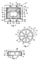
- each tooth-form element 2, 4 has a corresponding recess section 5-1, 5-2, wherein the recess sections 5-1, 5-2 form the recess 5, which corresponds to the at least one artificial tooth to be formed.
- the recess 5 forms a negative image of the at least one artificial tooth to be formed.
- Fig. 1 shows the tooth mold elements 2, 4 without introduced into the recess 5 photocurable material.
- the tooth-form elements 3, 4 of FIG. 1 are made of a light-transmitting material, here clear silicone.
- the two tooth form elements 3, 4 together form a complete tooth form, in which the artificial tooth, for example a crown, can be formed.
- Separating surfaces 6, 8, with which the two tooth-form elements are positioned on each other, are preferably formed as substantially flat surfaces, as shown in Fig. 1.
- the parting surfaces can be a positioning agent 9, by which a tooth mold element 2 can be positioned defined relative to the other tooth mold element 4.
- the positioning means 9 may, for example, have one or more elevations in one tooth-form element 2, which mate with corresponding depressions in the other tooth-form element 4 and ensure correct positioning of the tooth-form elements 2, 4 relative to one another.
- the parting surfaces 6, 8 may have any other shape or shape.
- the tooth-form elements 2, 4 are each arranged in a base element 10, 12 assigned to them.
- the base elements 10, 12 form part of the tooth form 1.
- the base elements 10, 12 each have a wall 14 which, in the embodiment of metal shown in FIG. H. made of opaque material. Each wall has an inner side 16 opposite the associated tooth-form element and an outer side 18 facing away from the respective tooth-form element.
- the base elements 10, 12 are designed to provide light on the inner side 16 of the wall 14, for hardening the photohardenable material in the recess 5 formed by the tooth form elements 2, 4.
- the wall 14 is partially permeable to light.
- the wall 14 on openings 20, for the passage of light from the outside 18 to the inside 16 of the wall.
- the light for curing the photocurable material is provided by a light source 22 disposed on the outside 18 of the wall 14.
- the light source 22 may include one or more bulbs, for example, four bulbs as shown in Fig. 1.
- Fig. 1 further shows a light oven 24 in which the tooth mold 1 can be arranged on a support 26 and which contains the light source 22.
- a conventional light oven used in dental technology can be used, which provides light for curing light-curable material.
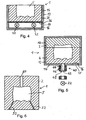
- FIGS. 2 and 3 relate to a further embodiment of a tooth form 1.
- This tooth form contains two tooth form elements 2, 4, of which only the upper tooth form element 2, corresponding to the tooth form element 2 of FIG. 1, is shown.
- a ceiling 30 of the wall 14 of the upper base member 2 has circular segment-shaped openings 20 for the passage of light from the outside of the wall 14 to the inside 16 of the wall 14.
- the side wall 32 of the upper base member 10 has rectangular openings 20 for the passage of light from the outside 18 to the inside 16 of the side wall 32, as shown in Fig. 3.
- a positioning means 34 by means of which the upper base element 10 can be positioned defined relative to the lower base element 12.
- This defined positionability is advantageous because it avoids that a user of the tooth mold 1, the base elements 10, 12 and thereby arranged in the base elements 10, 12 tooth mold elements 2, 4 arranges misaligned to each other and thereby the quality of the incorrectly assembled in this Reduces tooth shape produced artificial tooth or makes the artificial tooth completely unusable.
- the positioning means 34 in the embodiment shown in Figs. 2 and 3 consists of three recesses mating with corresponding projections in the lower base member 12 (not shown), thereby ensuring the positioning of the upper base member 10 relative to the lower base member 12 in a unique manner.
- the size of the openings 20 may be adapted to the degree of elasticity of the tooth-form elements 2, 4.
- the apertures 20 can be made larger, whereas for an elastic, soft material, the apertures 20 smaller must be selected in order to avoid deformation of the relevant tooth form element under the pressure of the arranged in the recess 5 photocurable material.
- the associated lower base member 12 may be generally configured in function and / or shape corresponding to the upper base member 10.
- a light source 22 is disposed on the inner side 16 of the wall 14, from which light can be emitted for curing the photocurable material.
- the light source 22 may comprise one or more light sources, for example two light sources as shown in FIG. 4.
- the number and arrangement of the lighting means is preferably adapted to the size, the shape and the number of artificial teeth to be formed, and thus to the shape and size of the recess 5.
- the light source 22 may be associated with a protective element 36 which protects the light source 22 from contamination and / or damage.
- the protective element 36 can be formed, for example, by a glass plate or a plexiglass plate, or any other light-transmissive element, in particular by a window element which is permeable to the light for hardening the photocurable material in the recess 5.
- the embodiment of a base element 12 shown in FIG. 4 has a wall 14 without openings.
- the wall 14 has on its inner side 16 a mirror layer 38, which reflects light emitted by the light source 22, in particular in the direction of the recess 5. In this way, the efficiency of the light source 22 with respect to the curing of the photocurable material in the recess 5 is increased.
- FIG. 5 shows a further embodiment of a base element 12 according to the invention, which has an optical waveguide coupling 40 which is connected to a light guide 42 is detachable.
- the optical fiber coupling 40 By the optical fiber coupling 40, a light emitted from the light guide light on the inner side 16 of the wall 14 can be brought.
- Fig. 5 by way of example only a single optical fiber coupling 40 is shown. However, it is understood that depending on the size and shape of the base member 12 or depending on the size, shape and number of teeth to be formed two or more fiber optic couplings can be provided.
- each base element may have at least one optical fiber coupling.
- the at least one optical fiber coupling can be arranged centrally with respect to the wall 14, as shown in FIG.
- the optical fiber coupling can also be arranged laterally, so that the light beam coupled onto the inner side 16 of the wall 14 does not strike the light-conducting material directly, but is directed primarily past it. In this way, a uniform distribution of the coupled-in light in the at least one tooth-form element can be achieved, in particular by using a wall 14, which is mirror-coated at least in sections on the inner side 16.
- the optical fiber coupling 40 may, for example, have a thread 44 on which a corresponding counterpart 46 of the light guide 42 can be screwed to form a screw connection between the base member 12 and the light guide 42.
- a thread 44 on which a corresponding counterpart 46 of the light guide 42 can be screwed to form a screw connection between the base member 12 and the light guide 42.
- an opening 48 extends from the outside 18 up to the inner side 16 of the wall 14.
- any other connection may be provided, for example a bayonet, snap or plug connection.
- FIG. 6 shows an embodiment of a tooth-form element 2, wherein the recess 5 for forming the at least one artificial tooth is formed by a single tooth-form element 2.
- the tooth-form element 2 in FIG. 6 has a feed channel 50, through which light-curable material can be introduced into the recess 5.
- the tooth-form element 2 of FIG. 6 has two Overflow channels 52, via which an excess of a introduced into the recess 5 photocurable material can escape again. Through the overflow channels 52 a complete filling of the recess 5 is ensured.
- the tooth-form element 2 as illustrated, for example, in FIG. 6, may be associated with a single base element (not shown). Alternatively, the tooth form element 2 may be associated with two or more base elements.
- Figures 7, 8 and 9 illustrate a preferred method of making an artificial tooth according to the invention.
- a tooth form is used in which the recess 5 corresponding to the at least one tooth to be formed is formed by two tooth form elements 2, 4.
- the tooth-form elements 2, 4 each have a base element 10, 12.
- the basic elements are here made of translucent plastic, such as Plexiglas formed.
- the tooth-forming element 2 forming the tooth neck can be designed to produce a depression on the underside of the artificial tooth, as is usually the case with a crown.
- the depression corresponds in shape here in a known manner the tooth stump of the tooth, which is crowned with the crown (the artificial tooth).
- the light-curable material 56 is introduced into one of the tooth mold elements, for example the lower tooth mold element 4, as shown in FIG. 7, and then the upper tooth mold element 2 is placed on the lower tooth mold element 4.
- This configuration is shown in FIG.
- light-curable material can also be introduced into both tooth-form elements 2, 4.
- the recess 5 is filled with the photocurable material 56 and excess photocurable material is pressed out between the parting surfaces 6, 8 of the tooth-form elements 2 and 4, respectively.
- the tooth structure with the light-curable material is introduced into one of the tooth shape elements. By Beaube the photocurable material in the recess 5 with light of this photocurable material is cured.
- the artificial tooth 58 formed in this way has the desired shape, it usually does not yet meet the aesthetic requirements for an artificial tooth. For this reason, the artificial tooth is preferably built up from two or more layers, wherein two layers are generally sufficient when using a method according to the invention.
- the tooth-form elements 2, 4 are separated from one another, and a part of the hardened light-curable material is removed, for example abraded. In this way, a tooth blank is obtained, as indicated in FIG. 4 by the reference numeral 60.
- a tooth-form element for example the tooth-shaped element 2 assigned to the tooth neck 62, is designed such that it exerts a higher retention force on the tooth formed in the recess 5 than the other tooth-form element or elements 4, so that during a separation the tooth-form elements 2, 4, the already hardened photocurable material (tooth 58) on the tooth neck 62 associated tooth forming element 2 adhere. This facilitates the handling and further processing of the already light-cured material.
- the further photohardenable material 64 is preferably selected so that the color, opalescence and haze of the resulting tooth conform to the corresponding natural tooth and inconspicuously fit into the remaining dentition of the patient.
- the tooth blank 60 can be released from the tooth mold element 4 associated with the tooth neck 62 and introduced independently of this tooth mold element 4 into the recess 5-2 formed by the remaining tooth mold elements 4.
- FIGS. 10 and 11 show an embodiment of a tooth-form element 4 which is in a plastically deformable state.
- a tooth form element 4 allows the molding of at least a part of at least one tooth 70 and thereby forming a recess 5-2, in which a photocurable material can be introduced.
- a tooth-form element 4 is distributed together with a base element 12.
- the base member 12 is a disposable member that is discarded or recycled after fabrication of the desired artificial tooth.
- the surface 72 of the tooth mold element 4, in which the Quiltende tooth 70, which may be a natural tooth or a dental model, is pressed by a protective film 74 from drying or before Protected a reaction with the ambient air.
- the tooth-form element 4 is pressed onto the tooth 70 to be shaped, so that a recess 5-2 corresponding to the tooth 70 forms in the tooth-molding material 4 (FIG. 11).
- the photohardenable material can be introduced into the recess 5 to form the artificial tooth.
- the surface 72 of the tooth-forming element 4 shown in FIG. 12 forms a tremor surface described above.
- FIGS. 1 to 11 show by way of example in the drawings. Rather, the invention will be apparent from a consideration of the claims as a matter of general description, the descriptions, the exemplary embodiments and the variants mentioned below, which should give an expert hints to other possible embodiments, but without limiting the possibilities of variation to these references.
- the recess formed by the tooth forming elements may correspond to a plurality of teeth.
- basic elements and tooth mold elements are shown, which have a rectangular cross-section. Deviating from this, any other cross-sectional areas are possible; In particular, the light distribution in the base element can be changed by the cross-sectional shape and adapted to the requirements of the respective artificial tooth to be formed.
- these may be formed of translucent material, for example made of translucent plastic.
- the material of the at least one tooth form element and / or the dimensions of the at least one tooth form element with respect to the recess formed by it can be dimensioned according to an embodiment of the invention so that the at least one tooth form element acts as a light guide.
- a light provided on the inside of the wall is distributed in the tooth-form element, and even when only a few light sources / illuminants are used, an all-sided loading of the photocurable material with light can be achieved.
- the material and / or the shape of one or more base elements may be selected such that the base element forms a light guide, wherein a light introduced into the base element by a light coupling section of the base element propagates in the base element. In this way, with a few light sources / bulbs an all-sided loading of the photocurable material can be achieved with light.
Landscapes
- Health & Medical Sciences (AREA)
- Oral & Maxillofacial Surgery (AREA)
- Dentistry (AREA)
- Epidemiology (AREA)
- Life Sciences & Earth Sciences (AREA)
- Animal Behavior & Ethology (AREA)
- General Health & Medical Sciences (AREA)
- Public Health (AREA)
- Veterinary Medicine (AREA)
- Engineering & Computer Science (AREA)
- Manufacturing & Machinery (AREA)
- Dental Tools And Instruments Or Auxiliary Dental Instruments (AREA)
Applications Claiming Priority (1)
| Application Number | Priority Date | Filing Date | Title |
|---|---|---|---|
| DE102004052393A DE102004052393A1 (de) | 2004-10-28 | 2004-10-28 | Zahnformelement und Basiselement |
Publications (1)
| Publication Number | Publication Date |
|---|---|
| EP1652492A1 true EP1652492A1 (fr) | 2006-05-03 |
Family
ID=35583364
Family Applications (1)
| Application Number | Title | Priority Date | Filing Date |
|---|---|---|---|
| EP05023671A Withdrawn EP1652492A1 (fr) | 2004-10-28 | 2005-10-28 | Méthode et appareil pour la fabrication d'une dent artificièlle |
Country Status (2)
| Country | Link |
|---|---|
| EP (1) | EP1652492A1 (fr) |
| DE (1) | DE102004052393A1 (fr) |
Cited By (1)
| Publication number | Priority date | Publication date | Assignee | Title |
|---|---|---|---|---|
| EP1864627A3 (fr) * | 2006-06-07 | 2008-02-20 | Heraeus Kulzer GmbH | Procédé destiné à la fabrication de prothèse dentaire |
Citations (9)
| Publication number | Priority date | Publication date | Assignee | Title |
|---|---|---|---|---|
| DE3933803A1 (de) * | 1989-10-10 | 1991-04-18 | Achim Ehlers | Retentionen zum anbringen von kunststoffverbindungen auf grundrohlingen sowie verfahren zum befestigen der retentionen auf diesen, insbesondere zu reparaturzwecken |
| DE4005570A1 (de) * | 1990-02-22 | 1991-08-29 | Schuetz Dental Gmbh | Verfahren zur herstellung eines dentalen gegenstandes |
| EP0581226A2 (fr) * | 1992-07-31 | 1994-02-02 | Molten Corporation | Réacteur de photopolymérisation et petit appareil d'irradiation lumineuse pour usage dentaire |
| US5316473A (en) * | 1988-06-17 | 1994-05-31 | Dentsply Research & Development Corp. | Light curing apparatus and method |
| US5368481A (en) * | 1993-07-13 | 1994-11-29 | Hill; Steven J. | Dental mold apparatus |
| EP0678282A2 (fr) * | 1994-03-22 | 1995-10-25 | Minnesota Mining And Manufacturing Company | Porte-empreinte dentaire pour un matériau d'empreinte photodurcissable |
| US5575653A (en) * | 1992-04-01 | 1996-11-19 | Vita Zahnfabrik H. Rauter Gmbh & Co. Kg | Artificial tooth blank made in series production |
| US6332991B1 (en) * | 1997-05-29 | 2001-12-25 | Silvia Assi | Container and method for cross-linking composite materials on dental prosthesis |
| US20030222365A1 (en) * | 2002-06-01 | 2003-12-04 | Dan Vogel | System for fabrication of indirect dental restorations incorporating optical enhancement |
-
2004
- 2004-10-28 DE DE102004052393A patent/DE102004052393A1/de not_active Ceased
-
2005
- 2005-10-28 EP EP05023671A patent/EP1652492A1/fr not_active Withdrawn
Patent Citations (9)
| Publication number | Priority date | Publication date | Assignee | Title |
|---|---|---|---|---|
| US5316473A (en) * | 1988-06-17 | 1994-05-31 | Dentsply Research & Development Corp. | Light curing apparatus and method |
| DE3933803A1 (de) * | 1989-10-10 | 1991-04-18 | Achim Ehlers | Retentionen zum anbringen von kunststoffverbindungen auf grundrohlingen sowie verfahren zum befestigen der retentionen auf diesen, insbesondere zu reparaturzwecken |
| DE4005570A1 (de) * | 1990-02-22 | 1991-08-29 | Schuetz Dental Gmbh | Verfahren zur herstellung eines dentalen gegenstandes |
| US5575653A (en) * | 1992-04-01 | 1996-11-19 | Vita Zahnfabrik H. Rauter Gmbh & Co. Kg | Artificial tooth blank made in series production |
| EP0581226A2 (fr) * | 1992-07-31 | 1994-02-02 | Molten Corporation | Réacteur de photopolymérisation et petit appareil d'irradiation lumineuse pour usage dentaire |
| US5368481A (en) * | 1993-07-13 | 1994-11-29 | Hill; Steven J. | Dental mold apparatus |
| EP0678282A2 (fr) * | 1994-03-22 | 1995-10-25 | Minnesota Mining And Manufacturing Company | Porte-empreinte dentaire pour un matériau d'empreinte photodurcissable |
| US6332991B1 (en) * | 1997-05-29 | 2001-12-25 | Silvia Assi | Container and method for cross-linking composite materials on dental prosthesis |
| US20030222365A1 (en) * | 2002-06-01 | 2003-12-04 | Dan Vogel | System for fabrication of indirect dental restorations incorporating optical enhancement |
Cited By (1)
| Publication number | Priority date | Publication date | Assignee | Title |
|---|---|---|---|---|
| EP1864627A3 (fr) * | 2006-06-07 | 2008-02-20 | Heraeus Kulzer GmbH | Procédé destiné à la fabrication de prothèse dentaire |
Also Published As
| Publication number | Publication date |
|---|---|
| DE102004052393A1 (de) | 2006-05-11 |
Similar Documents
| Publication | Publication Date | Title |
|---|---|---|
| EP3223742B1 (fr) | Fabrication d'une prothèse dentaire par impression de la base prothétique sur les dents prothétiques | |
| DE60130139T2 (de) | Zahnärztliche fräsrohlingsanordnung sowie verfahren zu deren herstellung | |
| DE102014118231B3 (de) | Verfahren zur Herstellung einer Dentalprothese mit einer Schablone | |
| DE102014109563B4 (de) | Verfahren zur Herstellung einer Dentalprothese | |
| DE112015000144B4 (de) | Pressformen eines Zahnersatzes aufweisend Keramik, wie Zirkoniumdioxid, mit einer aufgerauten Oberfläche | |
| DE102009039880A1 (de) | An einem Zahn herzustellende Verblendung sowie ein hierzu geeignetes Verfahren | |
| DE102014105190A1 (de) | Verfahren zur Bearbeitung von vorkonfektionierten Prothesenzähnen | |
| DE102017113814B4 (de) | Verfahren zur Herstellung einer Dentalprothese mit definiertem Klebespalt | |
| CH676789A5 (fr) | ||
| EP3612131A1 (fr) | Procédé de fabrication d'une prothèse dentaire à racines parallèles des dents de la prothèse | |
| DE69935509T2 (de) | Verfahren zur herstellung von durchscheinenden zahnersätzen | |
| EP3285681B1 (fr) | Dispositif et procédé pour la fixation de dents prothétiques | |
| EP1523952A2 (fr) | Elément de restauration dentaire | |
| DE19814762A1 (de) | Verfahren zur Herstellung von Zahnersatz unter Verwendung von Vorformen | |
| DE10234994A1 (de) | Zahnverblendung und Vorrichtung zur Aufbringung einer Zahnverblendung | |
| DE102015106424A1 (de) | Verfahren zur Herstellung von Zahnersatz mit einem Kunststoffkern | |
| EP1652492A1 (fr) | Méthode et appareil pour la fabrication d'une dent artificièlle | |
| EP1264581B1 (fr) | Dent artificielle et son procédé de fabrication | |
| DE3941663C2 (fr) | ||
| EP3056165B1 (fr) | Dispositif medical dentaire comprenant une coque de transfert | |
| EP2965710A1 (fr) | Moules personnalisées | |
| DE69121582T2 (de) | Verfahren zum anpassen eines dentalen porzellanelements | |
| DE102021112178B4 (de) | Verfahren und Vorrichtung zur Herstellung einer Dentalprothese | |
| DE19803302A1 (de) | Komponenten für die Herstellung randspaltfreier Füllungen aus lichthärtbaren plastischen Füllungsmaterialien für menschliche Zähne | |
| DE60034857T2 (de) | Aus transparentem Material hergestellte Universalgiessform zur Herstellung von Zahnprothesen, insbesondere geeignet für lichtempfindliche Materialien |
Legal Events
| Date | Code | Title | Description |
|---|---|---|---|
| PUAI | Public reference made under article 153(3) epc to a published international application that has entered the european phase |
Free format text: ORIGINAL CODE: 0009012 |
|
| AK | Designated contracting states |
Kind code of ref document: A1 Designated state(s): AT BE BG CH CY CZ DE DK EE ES FI FR GB GR HU IE IS IT LI LT LU LV MC NL PL PT RO SE SI SK TR |
|
| AX | Request for extension of the european patent |
Extension state: AL BA HR MK YU |
|
| AKX | Designation fees paid | ||
| STAA | Information on the status of an ep patent application or granted ep patent |
Free format text: STATUS: THE APPLICATION IS DEEMED TO BE WITHDRAWN |
|
| 18D | Application deemed to be withdrawn |
Effective date: 20061104 |
|
| REG | Reference to a national code |
Ref country code: DE Ref legal event code: 8566 |