EP1652560B1 - Einstellungsvorrichtung für eine Vorderbacke einer Skibindung oder dergleichen - Google Patents
Einstellungsvorrichtung für eine Vorderbacke einer Skibindung oder dergleichen Download PDFInfo
- Publication number
- EP1652560B1 EP1652560B1 EP05022777A EP05022777A EP1652560B1 EP 1652560 B1 EP1652560 B1 EP 1652560B1 EP 05022777 A EP05022777 A EP 05022777A EP 05022777 A EP05022777 A EP 05022777A EP 1652560 B1 EP1652560 B1 EP 1652560B1
- Authority
- EP
- European Patent Office
- Prior art keywords
- base
- bar
- knob
- accessory
- gliding
- Prior art date
- Legal status (The legal status is an assumption and is not a legal conclusion. Google has not performed a legal analysis and makes no representation as to the accuracy of the status listed.)
- Expired - Lifetime
Links
Images

Classifications
-
- A—HUMAN NECESSITIES
- A63—SPORTS; GAMES; AMUSEMENTS
- A63C—SKATES; SKIS; ROLLER SKATES; DESIGN OR LAYOUT OF COURTS, RINKS OR THE LIKE
- A63C9/00—Ski bindings
- A63C9/005—Ski bindings with means for adjusting the position of a shoe holder or of the complete binding relative to the ski
Definitions
- the invention relates to an adjustable attachment device of an accessory on a gliding board, particularly adapted to the attachment to a ski of a stop before a ski boot fastening device, allowing its longitudinal adjustment.
- a general object of the present invention is to provide an adjustable attachment device of an accessory on a gliding board that does not have the above disadvantages.
- a first object of the invention is to provide an adjustable attachment device of an accessory on a gliding board, user friendly and easy to use in all conditions.
- a second object of the invention is to provide an adjustable attachment device of an accessory on a gliding board for fixing without play.
- a third object of the invention is to provide an adjustable attachment device of an accessory on a gliding board for secure attachment.
- a fourth object of the invention is to provide an adjustable attachment device of an accessory on a gliding board, simple and easy to assemble.
- a fifth object of the invention is to provide an adjustable and aesthetic attachment device of an accessory on a gliding board.
- the invention is based on an adjustable attachment device of an accessory on a gliding board comprising a base, comprising locations for fixing the accessory and in which is housed a bar having a toothed portion adapted for positioning in a complementary toothed portion integral with the gliding board, the bar being mounted rotatably on the base about an axis, comprising on both sides of this axis the toothed portion and an end, and comprising a handle that can occupy two different positions, comprising a camming surface cooperating with the end of the bar, so that a first position of the handle corresponds to a low position of the toothed portion, and a second position corresponds to a high position of the toothed portion.
- the bar may be arranged in the longitudinal direction of the base, the toothed portion being substantially in the central portion of the base and the end of the bar and the lever being towards one end of the base.
- the handle may have a cam surface including a first portion in contact with the end of the bar when the toothed portion and the handle are in a low position and a second portion at a greater distance from the axis of rotation of the handle which causes a downward movement of the end of the bar when the lever is in its second high position, corresponding to a high position of the toothed portion.
- the device may comprise a spring mounted on the base and exerting a force on the bar tending to maintain its toothed part in low position.
- the handle may include a second cam surface of which two portions are in contact with a piston of the base so that the piston exerts downward pressure when the handle is in its down position to block play of the base.
- the base may comprise at least one location for receiving a ski binding before stop and the handle can be positioned towards the rear end of the base for receiving a ski boot.
- the invention also relates to a front ski binding stop which comprises a fixing device adjustable from its longitudinal position according to the invention.
- the invention also relates to the assembly comprising the device for attaching an accessory to a gliding board described above and to an element intended to be firmly fixed to the gliding board and comprising a toothed portion corresponding to the toothed portion of the bar.
- the invention also relates to a ski comprising an adjustable attachment device of an accessory as described above.
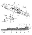
- the device comprises an elongate base 1, comprising a slot 2 in which is positioned a longitudinal bar 3.
- the location 2 consists of an opening 4 and a location 5 to respectively receive a toothed portion 6 of the bar 3 and a connection with a circular arc-shaped portion of the bar.
- This link allows the bar 3 to be rotatable about an axis 7 on the location 5 relative to the base 1, allowing the toothed portion 6 of the bar, which is in a lower plane and substantially parallel to the plane of the rest of the bar 3, to cross the opening 4 in its lowest position to be able to be fixed in a complementary toothed part integral with the gliding board, which will be described later, or occupy a higher position within the opening 4 in which it is released from the complementary toothed portion.
- This mechanism will be described in more detail with reference to FIGS. 4 to 9.
- the base 1 further comprises a means 8 for maintaining a spring 9 which has the effect of exerting a force downwardly on the toothed portion 6 of the bar in order to push it back to its lower position. It further comprises a housing 10 in which is mounted rotatably about an axis 11 a lever 12 whose first function is to act on the end 13 of the bar to allow it to move from its low position to its raised position.
- the device comprises a locking piston 14, surrounded by two return springs 15, all three mounted in three openings 16 of the base 1.
- the assembly is surmounted by a spring plate 17 connected to the locking piston 14 and cooperating with the joystick 12.
- FIG. 2 illustrates the previously described adjustment device mounted integrally on a gliding board, via an element 19 integral with the gliding board and comprising slides 20 on which the base 1 can slide by means of slides. corresponding longitudinal 21.
- the element 19 further comprises a portion 22 comprising two lateral rows 23 of teeth. These teeth are in a plane parallel to the element 19 and oriented transversely to the slides 20, directed towards a central opening 24 located between the two rows 23 of teeth.
- the dimensions of the central opening 24 correspond to the toothed portion 6 of the bar 3, whose teeth can thus be housed between the teeth of the rows 23 in order to fix the base 1 on the element 19 by preventing a longitudinal sliding of the base 1 relative to the gliding board.
- the base 1 comprises locations 25 adapted for attachment of an accessory such as a front stop ski attachment for example.
- Figure 3 shows the handle 12 which comprises an opening 26 for receiving an axis 11 and to be rotated about this axis. It has a shape particularly adapted to its manual rotation about this axis 11. It comprises a first cam surface comprising a first portion 27 and a second portion 28, intended to cooperate with the end 13 of the bar 3. It comprises of plus a second cam surface including a first portion 29 and a second portion 30 for cooperating with the spring plate 17.
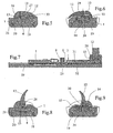
- Figures 4 to 6 illustrate the device in a first position of the lever 12 which corresponds to the fixing position of the base 1.
- the lever 12 is in its lowered position on the base 1 and its surface cam 27 is in contact with the end 13 of the bar 3.
- the end 13 of the bar occupies a raised position and the spring 9 keeps the toothed portion 6 in its lower position in which it passes through the opening 4 of the base to be housed in the teeth of the rows 23 of the element 19 on the gliding board, thus preventing longitudinal movement of the base 1.
- the upper portion 31 of the bar 3 is in contact with a corresponding portion 32 of the base over a length of about one third of the total length of the bar, which ensures a precise positioning of the bar 3.
- this part has a slight slope which allows to its end 13 to have a potential freedom of movement relative to the base 1 which does not follow this slope towards its end and thus releases a space 33 between the end 13 of the bar and its housing 4 provided in the base 1.
- FIG. 6 illustrates the positioning of the second cam surface of the lever 12 in this low position in which its cam surface 29 is in contact with the plate 17 and the piston 14, pushing it back into a low position such as the base 34 of the piston bears against the element 19.
- the piston 14 also prevents relative movements between the base 1 and the element 19 and performs a function of blocking games, important to ensure a good connection between the stop and ski, necessary for precise skiing guidance.
- the bar 3 comprises wider portions 35 which are housed in locations 36 of the same size of the housing 4 of the base 1. This has the effect of preventing any relative longitudinal movement between the bar 3 and the base 1. Thus, the fixing of the bar 3 in the element 19 also fixes the base 1.
- Figures 7 to 9 illustrate the other extreme position of the lever 12, fully raised, in a configuration for the longitudinal adjustment of the base 1 on the ski.
- the cam surface 28 of the handle rests on the end 13 of the bar 3.
- This surface 28 is further from the axis of rotation 11 of the bar than the surface 27, the end 13 the bar is pushed downwards and passes through the space 33 until it comes to bear on the housing 4 of the base 1.
- This displacement causes by leverage the rotation of the bar 3 about the axis 7, which raises its parts 31 and 6 by opposing the spring pressure force 9.
- the toothed portion 6 is then sufficiently raised to completely out its teeth rows 23.
- the base 1 then becomes movable longitudinally along the rails 20, 21 with respect to the element 19.
- the shape of the cam surface 28 allows the lever 12 to maintain this position stably.
- FIG. 9 shows the contact between the second cam surface 30 of the lever 12 and the piston 14.
- This second portion 30 of the second cam surface being closer to the axis of rotation 11 than the first portion 29 of the second cam surface, the piston 14 and the plate 17 occupy a higher position, pushed upwards by the springs 15, thus releasing a slight gap between the base 34 of the piston and the element 19 so as not to hinder the longitudinal displacement of the base 1.
- the toothed portion 6 of the base 1 is substantially in the center of the base 1, which allows the base 1 to hide at best the fastening device integral with the gliding board, ie the element 19 and its toothed portion 22, which is not aesthetically attractive.
- the lever 12 is positioned towards the rear of the base 1 in the longitudinal direction, which makes it possible, in the case of an application with a front stop in the locations 25, the positioning of a ski boot over the lever 12, inducing a locking and a holding case of the joystick in its low position and preventing accidental opening.
Landscapes
- Footwear And Its Accessory, Manufacturing Method And Apparatuses (AREA)
- Mechanical Control Devices (AREA)
Claims (9)
- Einstellbare Vorrichtung zur Befestigung eines Zubehörteils auf einem Gleitbrett, mit einer Grundplatte (1) , die Stellen (25) zur Befestigung des Zubehörteils aufweist und in welcher ein Steg (3) angeordnet ist, der einen gezahnten Teil (6) hat, welcher in einen fest am Gleitbrett angebrachten komplementären gezahnten Teil eingreifen kann, wobei der Steg (3) um eine Achse (7) drehbar auf der Grundplatte (1) montiert ist, und mit einem Bedienungsorgan (12), das zwei verschiedene Stellungen einnehmen kann, dadurch gekennzeichnet, dass sich der gezahnte Teil (6) des Stegs (3) und ein Endabschnitt (13) des Stegs auf beiden Seiten der Achse befinden und dass das Bedienungsorgan (12) eine Nockenfläche aufweist, die mit dem Endabschnitt (13) des Stegs (3) derart zusammenwirkt, dass eine erste Stellung des Bedienungsorgans (12) einer unteren Position des gezahnten Teils (6) und eine zweite Stellung einer oberen Position des gezahnten Teils (6) entspricht.
- Vorrichtung nach Anspruch 1, dadurch gekennzeichnet, dass der Steg (3) in Längsrichtung der Grundplatte angeordnet ist, dass sich der gezahnte Teil im wesentlichen im zentralen Bereich der Grundplatte (1) befindet und dass der Endabschnitt (13) des Stegs (3) und das Bedienungsorgan (12) an einem Ende der Grundplatte (1) angeordnet sind.
- Vorrichtung nach Anspruch 1 oder 2, dadurch gekennzeichnet, dass das Bedienungsorgan (12) eine Nockenoberfläche hat, die einen ersten Teil (27), der sich in Kontakt mit dem Endabschnitt (13) des Stegs (3) befindet, wenn der gezahnte Teil und das Bedienungsorgan (12) eine untere Position einnehmen, und in grösserem Abstand von der Drehachse (11) des Bedienungsorgans (12) einen zweiten Teil (28) aufweist, welcher eine Verschiebung des Endabschnitts (13) des Stegs (3) nach unten bewirkt, wenn sich das Bedienungsorgan (12) in seiner zweiten oberen Position befindet, welche einer oberen Position des gezahnten Teils (6) entspricht.
- Vorrichtung nach einem der vorangehenden Ansprüche, da durch gekennzeichnet, dass sie eine auf der Grundplatte (1) montierte Feder (9) aufweist, die eine Kraft auf den Steg ausübt, welche dessen gezahnten Teil (6) in der unteren Position zu halten sucht.
- Vorrichtung nach einem der vorangehenden Ansprüche, dadurch gekennzeichnet, dass das Bedienungsorgan (12) eine zweite Nockenoberflächge hat, deren zwei Abschnitte (29, 30) sich in Kontakt mit einem Kolben (14) der Grundplatte befinden, derart, dass dieser Kolben einen nach unten gerichteten Druck ausübt, wenn das Bedienungsorgan (12) seine untere Position einnimmt, um die Spielräume der Grundplatte (1) zu blockieren.
- Vorrichtung nach Anspruch 2, dadurch gekennzeichnet, dass die Grundplatte (1) wenigstens eine Stelle (25) zur Aufnahme eines Vorderbackens einer Schibindung aufweist und dass das Bedienungsorgan (12) am hinteren Ende der Grundplatte angeordnet ist, welches zur Aufnahme eines Schischuhs bestimmt ist.
- Vorderbacken einer Schibindung, dadurch gekennzeichnet, dass er eine einstellbare Befestigungsvorrichtung zum Einstellen seiner Längsposition nach einem der Ansprüche 1 bis 6 aufweist.
- Vorrichtung zum Befestigen eines Zubehörteils auf einem Gleitbrett, dadurch gekennzeichnet, dass sie eine Vorrichtung nach einem der Ansprüche 1 bis 6 und ein Element (19) aufweist, das dazu bestimmt ist, fest auf dem Gleitbrett angebracht zu werden, und welches einen gezahnten Teil (22) aufweist, der dem gezahnten Teil (6) des Stegs (3) entspricht.
- Schi, dadurch gekennzeichnet, dass er eine Vorrichtung nach einem der vorangehenden Ansprüche aufweist.
Applications Claiming Priority (1)
| Application Number | Priority Date | Filing Date | Title |
|---|---|---|---|
| FR0411479A FR2877234B1 (fr) | 2004-10-28 | 2004-10-28 | Dispositif de reglage pour accessoire tel une butee avant de fixation de ski |
Publications (2)
| Publication Number | Publication Date |
|---|---|
| EP1652560A1 EP1652560A1 (de) | 2006-05-03 |
| EP1652560B1 true EP1652560B1 (de) | 2007-01-10 |
Family
ID=34952509
Family Applications (1)
| Application Number | Title | Priority Date | Filing Date |
|---|---|---|---|
| EP05022777A Expired - Lifetime EP1652560B1 (de) | 2004-10-28 | 2005-10-19 | Einstellungsvorrichtung für eine Vorderbacke einer Skibindung oder dergleichen |
Country Status (4)
| Country | Link |
|---|---|
| US (1) | US7393002B2 (de) |
| EP (1) | EP1652560B1 (de) |
| DE (1) | DE602005000441T2 (de) |
| FR (1) | FR2877234B1 (de) |
Families Citing this family (9)
| Publication number | Priority date | Publication date | Assignee | Title |
|---|---|---|---|---|
| FR2906156B1 (fr) * | 2006-09-27 | 2010-04-23 | Rossignol Sa | Dispositif de retenue et reglage en position longtudinale d'une fixation sur une planche de glisse |
| AT11239U1 (de) * | 2008-11-03 | 2010-07-15 | Atomic Austria Gmbh | Schibindung mit einer positionier- und fixiervorrichtung für deren backenkörper |
| FR2959671B1 (fr) * | 2010-05-05 | 2013-07-19 | Rossignol Sa | Element de fixation a position reglable sur une planche de glisse |
| WO2012045329A1 (en) | 2010-10-04 | 2012-04-12 | Madshus As | Ski binding |
| DE102010048963A1 (de) | 2010-10-20 | 2012-04-26 | Marker Deutschland Gmbh | Bindung für ein Gleitbrett mit in Längsrichtung verstellbaren Halte einheiten |
| DE202015009508U1 (de) * | 2014-03-19 | 2018-01-15 | Madshus As | Mechanismus zum Verriegeln einer Skibindung in der Längsrichtung auf einer Begfestigungsplatte |
| DE102014104473B4 (de) * | 2014-03-28 | 2026-05-07 | Marker Deutschland Gmbh | Auslösebindung mit Hebel zur Festlegung und Freigabe eines Schuhhalteaggregats |
| US20170173443A1 (en) * | 2014-03-31 | 2017-06-22 | Vist Tech S.R.L. | Ski binding |
| FR3166552A1 (fr) | 2024-09-24 | 2026-03-27 | Salomon Sas | Dispositif de réglage de la position d’un élément de fixation de chaussure sur une planche de glisse ou de marche |
Family Cites Families (12)
| Publication number | Priority date | Publication date | Assignee | Title |
|---|---|---|---|---|
| FR2153827A5 (de) * | 1971-09-22 | 1973-05-04 | Ramillon Rene | |
| AT367642B (de) * | 1980-06-12 | 1982-07-26 | Tyrolia Freizeitgeraete | Verstelleinrichtung fuer einen skibindungsteil |
| AT376572B (de) * | 1980-11-14 | 1984-12-10 | Tyrolia Freizeitgeraete | Verstellvorrichtung |
| AT377701B (de) * | 1983-03-04 | 1985-04-25 | Tyrolia Freizeitgeraete | Vorrichtung zur laengsverstellung |
| AT380639B (de) * | 1984-04-27 | 1986-06-25 | Amf Sport Freizeitgeraete | Skibindungsteil, insbesondere vorderbacken |
| FR2578434B1 (fr) * | 1985-03-11 | 1987-10-09 | Salomon Sa | Dispositif de reglage de la position longitudinale d'une fixation de securite pour ski |
| US5344179A (en) * | 1991-11-28 | 1994-09-06 | Fritschi Ag. Apparatebau | Adjustable length binding system for snowboards having independently variable heel and toe spans |
| AT398701B (de) * | 1992-10-23 | 1995-01-25 | Tyrolia Freizeitgeraete | Skibindung mit einem fersenteil |
| AT402021B (de) * | 1994-05-30 | 1997-01-27 | Tyrolia Freizeitgeraete | Skibindung |
| FR2742345B1 (fr) * | 1995-12-13 | 1998-02-27 | Look Fixations Sa | Dispositif de montage d'un element de fixation de ski sur un ski |
| FR2775195B1 (fr) * | 1998-02-26 | 2000-04-21 | Look Fixations Sa | Fixation de ski |
| SI21450A (sl) * | 2003-04-23 | 2004-10-31 | Elan, D.D. | Smučka z vgrajenim sklopom za pozicioniranje smučarske vezi in utrditev le-te v izbranem položaju |
-
2004
- 2004-10-28 FR FR0411479A patent/FR2877234B1/fr not_active Expired - Fee Related
-
2005
- 2005-10-18 US US11/253,030 patent/US7393002B2/en not_active Expired - Fee Related
- 2005-10-19 DE DE602005000441T patent/DE602005000441T2/de not_active Expired - Lifetime
- 2005-10-19 EP EP05022777A patent/EP1652560B1/de not_active Expired - Lifetime
Also Published As
| Publication number | Publication date |
|---|---|
| FR2877234A1 (fr) | 2006-05-05 |
| US20060091644A1 (en) | 2006-05-04 |
| DE602005000441D1 (de) | 2007-02-22 |
| US7393002B2 (en) | 2008-07-01 |
| FR2877234B1 (fr) | 2007-01-19 |
| EP1652560A1 (de) | 2006-05-03 |
| DE602005000441T2 (de) | 2007-11-15 |
Similar Documents
| Publication | Publication Date | Title |
|---|---|---|
| EP3135350B1 (de) | Bremsvorrichtung zum befestigen eines snowboards | |
| EP0634252A1 (de) | Taschenmesser mit einer verriegelbaren Klinge und einer Druckknopfentriegelungsvorrichtung | |
| EP1652560B1 (de) | Einstellungsvorrichtung für eine Vorderbacke einer Skibindung oder dergleichen | |
| EP0085313B1 (de) | Sicherheitsskibindung | |
| EP0771228B1 (de) | Bindung für einen schuh auf einem snowboard | |
| EP3416732B1 (de) | Fersenhalter für ein skischuh mit einem einstiegspedal, wobei das einstiegspedal relativ zum fernsehenhalter mobil ist. | |
| EP1652559B1 (de) | Einstellungsvorrichtung für eine Fersenbacke einer Skibindung oder dergleichen | |
| EP0956886B1 (de) | Trägerplatte zwischen Schuh und Snowboard | |
| EP1935461A1 (de) | Mit einem mindestens zwischen zwei Positionen hin und her schaltbaren, beweglichen Knopf ausgestatteter Artikel | |
| EP2903702B1 (de) | Bindungssystem für ein touring-snowboard | |
| EP3785772B1 (de) | Haltevorrichtungen für gleitbrett | |
| FR2666020A1 (fr) | Fixation pour ski de fond. | |
| FR2742997A1 (fr) | Perfectionnement pour dispositif de retenue d'une chaussure a une planche de glisse pour neige | |
| EP1226769B1 (de) | Sportschuh mit in Querrichtung verstellbarer Spannvorrichtung | |
| EP4043290B1 (de) | Haltevorrichtung für ein tragbares elektronisches gerät in einem kraftfahrzeug | |
| FR2758469A1 (fr) | Dispositif de fixation de chaussure pour article de sport de glisse | |
| FR3066701A1 (fr) | Dispositif arriere de fixation de ski a dispositif de reglage debrayable | |
| FR3072884A1 (fr) | Butee de dispositif de fixation d'une chaussure | |
| EP2386333A1 (de) | Befestigungselement mit einstellbarer Position auf einem Schneegleitbrett | |
| FR3015907A1 (fr) | Engin de glisse | |
| CH483266A (fr) | Butée de sécurité avant pour fixation de ski | |
| FR3107193A1 (fr) | Dispositif de freinage pour ski de randonnée | |
| FR2794028A1 (fr) | Fixation declenchable pour planche de glisse | |
| FR2462175A1 (fr) | Dispositif anti-recul pour ski de fond | |
| FR2788443A1 (fr) | Fixation declenchable pour planche de glisse |
Legal Events
| Date | Code | Title | Description |
|---|---|---|---|
| PUAI | Public reference made under article 153(3) epc to a published international application that has entered the european phase |
Free format text: ORIGINAL CODE: 0009012 |
|
| AK | Designated contracting states |
Kind code of ref document: A1 Designated state(s): AT BE BG CH CY CZ DE DK EE ES FI FR GB GR HU IE IS IT LI LT LU LV MC NL PL PT RO SE SI SK TR |
|
| AX | Request for extension of the european patent |
Extension state: AL BA HR MK YU |
|
| 17P | Request for examination filed |
Effective date: 20060502 |
|
| GRAP | Despatch of communication of intention to grant a patent |
Free format text: ORIGINAL CODE: EPIDOSNIGR1 |
|
| GRAS | Grant fee paid |
Free format text: ORIGINAL CODE: EPIDOSNIGR3 |
|
| GRAA | (expected) grant |
Free format text: ORIGINAL CODE: 0009210 |
|
| AK | Designated contracting states |
Kind code of ref document: B1 Designated state(s): AT CH DE FR IT LI |
|
| AKX | Designation fees paid |
Designated state(s): AT CH DE FR IT LI |
|
| REF | Corresponds to: |
Ref document number: 602005000441 Country of ref document: DE Date of ref document: 20070222 Kind code of ref document: P |
|
| REG | Reference to a national code |
Ref country code: CH Ref legal event code: NV Representative=s name: BUGNION S.A. |
|
| PLBE | No opposition filed within time limit |
Free format text: ORIGINAL CODE: 0009261 |
|
| STAA | Information on the status of an ep patent application or granted ep patent |
Free format text: STATUS: NO OPPOSITION FILED WITHIN TIME LIMIT |
|
| 26N | No opposition filed |
Effective date: 20071011 |
|
| PGFP | Annual fee paid to national office [announced via postgrant information from national office to epo] |
Ref country code: AT Payment date: 20090921 Year of fee payment: 5 |
|
| REG | Reference to a national code |
Ref country code: CH Ref legal event code: PL |
|
| PG25 | Lapsed in a contracting state [announced via postgrant information from national office to epo] |
Ref country code: LI Free format text: LAPSE BECAUSE OF NON-PAYMENT OF DUE FEES Effective date: 20091031 Ref country code: CH Free format text: LAPSE BECAUSE OF NON-PAYMENT OF DUE FEES Effective date: 20091031 |
|
| PG25 | Lapsed in a contracting state [announced via postgrant information from national office to epo] |
Ref country code: AT Free format text: LAPSE BECAUSE OF NON-PAYMENT OF DUE FEES Effective date: 20101019 |
|
| PGFP | Annual fee paid to national office [announced via postgrant information from national office to epo] |
Ref country code: IT Payment date: 20081031 Year of fee payment: 4 |
|
| PGFP | Annual fee paid to national office [announced via postgrant information from national office to epo] |
Ref country code: DE Payment date: 20131029 Year of fee payment: 9 |
|
| REG | Reference to a national code |
Ref country code: DE Ref legal event code: R119 Ref document number: 602005000441 Country of ref document: DE |
|
| PG25 | Lapsed in a contracting state [announced via postgrant information from national office to epo] |
Ref country code: DE Free format text: LAPSE BECAUSE OF NON-PAYMENT OF DUE FEES Effective date: 20150501 |
|
| REG | Reference to a national code |
Ref country code: FR Ref legal event code: PLFP Year of fee payment: 11 |
|
| REG | Reference to a national code |
Ref country code: FR Ref legal event code: PLFP Year of fee payment: 12 |
|
| REG | Reference to a national code |
Ref country code: FR Ref legal event code: PLFP Year of fee payment: 13 |
|
| REG | Reference to a national code |
Ref country code: FR Ref legal event code: PLFP Year of fee payment: 14 |
|
| PGFP | Annual fee paid to national office [announced via postgrant information from national office to epo] |
Ref country code: FR Payment date: 20231025 Year of fee payment: 19 |
|
| PG25 | Lapsed in a contracting state [announced via postgrant information from national office to epo] |
Ref country code: FR Free format text: LAPSE BECAUSE OF NON-PAYMENT OF DUE FEES Effective date: 20241031 |