EP1652559B1 - Einstellungsvorrichtung für eine Fersenbacke einer Skibindung oder dergleichen - Google Patents
Einstellungsvorrichtung für eine Fersenbacke einer Skibindung oder dergleichen Download PDFInfo
- Publication number
- EP1652559B1 EP1652559B1 EP05022776A EP05022776A EP1652559B1 EP 1652559 B1 EP1652559 B1 EP 1652559B1 EP 05022776 A EP05022776 A EP 05022776A EP 05022776 A EP05022776 A EP 05022776A EP 1652559 B1 EP1652559 B1 EP 1652559B1
- Authority
- EP
- European Patent Office
- Prior art keywords
- base
- gliding board
- accessory
- bar
- lever
- Prior art date
- Legal status (The legal status is an assumption and is not a legal conclusion. Google has not performed a legal analysis and makes no representation as to the accuracy of the status listed.)
- Expired - Lifetime
Links
Images




Classifications
-
- A—HUMAN NECESSITIES
- A63—SPORTS; GAMES; AMUSEMENTS
- A63C—SKATES; SKIS; ROLLER SKATES; DESIGN OR LAYOUT OF COURTS, RINKS OR THE LIKE
- A63C9/00—Ski bindings
- A63C9/005—Ski bindings with means for adjusting the position of a shoe holder or of the complete binding relative to the ski
-
- A—HUMAN NECESSITIES
- A63—SPORTS; GAMES; AMUSEMENTS
- A63C—SKATES; SKIS; ROLLER SKATES; DESIGN OR LAYOUT OF COURTS, RINKS OR THE LIKE
- A63C9/00—Ski bindings
- A63C9/08—Ski bindings yieldable or self-releasing in the event of an accident, i.e. safety bindings
- A63C9/084—Ski bindings yieldable or self-releasing in the event of an accident, i.e. safety bindings with heel hold-downs, e.g. swingable
Definitions
- the invention relates to an adjustable attachment device of an accessory on a gliding board, particularly adapted to the attachment on a ski of a heel of a ski boot fastening device, allowing its longitudinal adjustment.
- Various devices are known for adjusting the longitudinal position of a heel piece of a ski boot binding device in order to adapt the binding to different lengths of shoes.
- a common solution of the prior art is based firstly on an element positioned on the ski having guide rails and a toothed portion, and secondly on a heel mounted on a base and provided with guide rails and of a complementary toothed part.
- the two complementary toothed parts can be nested and block the longitudinal movement of the heel in the rails.
- a means for releasing these toothed portions makes it possible to obtain a movement of the heel piece for adjusting its position.
- the document US-A-5,738,364 describes an adjustable device for fixing a heel piece on a ski comprising a base on which is articulated the heel and in which is housed a bar having projections adapted for positioning in complementary cavities of a part integral with the ski, and comprising a lever consisting of a U-shaped plate and two wings forming levers, the lever being movable in rotation within the base, the bar having a degree of freedom and a portion in contact with the hollow of the U of the lever, so that a first position of the handle corresponds to the lower position of the part having projections, and a second position to a high position of this part.
- a general object of the present invention is to provide an adjustable attachment device of an accessory on a gliding board that does not have the above disadvantages.
- a first object of the invention is to provide an adjustable attachment device of an accessory on a gliding board, user friendly and easy to use in all conditions.
- a second object of the invention is to provide an adjustable attachment device of an accessory on a gliding board, simple and easy to assemble.
- a third object of the invention is to provide an aesthetically adjustable fastening device of an accessory on a gliding board.
- a fourth object of the invention is to provide a compact, space-saving fastening device.
- a fifth object of the invention is to provide an adjustable attachment device of an accessory on a gliding board for secure attachment.
- the invention is based on an adjustable attachment device of an accessory on a gliding board comprising a base, comprising means for attaching the accessory and in which is housed a bar having a toothed portion adapted for positioning in a toothed portion complementary integral with the gliding board, comprising a crankshaft movable in rotation within the base, one end of which is connected to a handle, the bar having a degree of freedom and a portion in contact with the bent portion of the crankshaft, so that a first position of the handle corresponds to the low position of the toothed part, and a second position corresponds to a high position of the toothed part.
- the bar can be fixed to the base at one end, the portion in contact with the crankshaft being towards the other end.
- the bar may be disposed in the longitudinal direction of the base, the toothed portion being substantially in the central portion of the base.
- a spring may be mounted in the base so as to exert a downward force on the toothed portion of the bar.
- the crankshaft may be transverse to the base, have the bent portion in its central portion, the lever being in a lateral zone outside the base.
- the handle may then have a direction substantially parallel to the gliding board when the toothed portion is in its low position, and an upward position at an angle of about 45 degrees when the toothed portion is in its up position.
- crankshaft can be arranged longitudinally to the base, have the bent portion towards its end, the lever being in an area at the front or rear of the base.
- the joystick can then presenting a direction substantially parallel to the gliding board when the toothed portion is in its low position, and a position raised by a quarter of a turn when the toothed portion is in its high position.
- the base comprises at least one location for receiving a ski binding heel and the handle is positioned towards the front end of the base for receiving a ski boot.
- the invention also relates to a ski binding heel comprising a fixing device adjustable from its longitudinal position on a gliding board as described above.
- It also relates to the assembly consisting of the attachment device of an accessory on a gliding board described above and of an element intended to be firmly fixed to the gliding board and comprising a toothed portion corresponding to the toothed part of the bar .
- the invention also relates to a ski comprising a device as described above.
- FIG. 1 A first embodiment of the invention is illustrated in Figures 1 to 10 .
- the adjustable attachment device of an accessory on a gliding board according to this embodiment comprises a base 1 on which are positioned two side rails 2 to allow the positioning of an accessory on the base 1 and its attachment.
- a bar 3 in the longitudinal direction of the base, comprising at a first end an opening 4 to accept a screw 5 to be fixed to the base, and comprising the another end a free surface 7 intended to cooperate with a crankshaft 8 actuated by a lever 9.
- the bar 3 comprises a toothed portion 6 in a lower plane, intended to cooperate with a complementary toothed portion connected to the gliding board, as will be illustrated later.
- the crankshaft 8 comprises a bent portion 10 in its central part, shown on the figure 2 . It is positioned through a lateral opening 11 of the base 1, transversely to the base 1 and the bar 3, so that its bent portion 10 is in contact with the lower surface of the end 7 of the 3. It comprises its two fixed ends rotatable on the side walls of the base 1, one of its ends thus resting on the opening 11 of the base and passing through it to be connected to the lever 9 which is thus positioned laterally outside the base 1.
- the Figures 3 to 6 illustrate the device in a first configuration, wherein the base 1 is fixed to the gliding board and can not move.
- the lever 9 is oriented in parallel to the longitudinal axis of the base 1 and the bent portion 10 is oriented downward at an angle of 45 degrees relative to the vertical.
- the bar 3 occupies a position generally parallel to the base 1, its toothed portion 6 being positioned in its lowest position.
- this adjustable fixing device is fixed on a gliding board via an element 12 fixed to the gliding board, comprising two lateral guide rails 13 cooperating with lateral rails not shown on the lower face of the board.
- base 1 and comprising a central opening in which is positioned an element 15 comprising two toothed side portions 16 flanking an opening 17.
- the toothed portions 16 have teeth oriented towards the opening 17 whose dimensions correspond to those of the toothed portion 6 of the bar 3.
- the teeth of the toothed portion 6 are therefore positioned between the teeth of the toothed portions 16 of the element 12, as is clearly visible in FIG. figure 6 , thus preventing any longitudinal sliding of the base 1 in the guide rails 13.
- a spring 18 is mounted within the base so as to exert a downward force on the toothed portion 6 of the bar 3, thus promoting the maintenance of the fixing position of this first configuration.
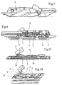
- FIGS. 7 to 10 illustrate the adjustable fastening device according to the first embodiment in a second configuration, wherein the base 1 can move longitudinally on the gliding board.
- the handle 9 has been raised by a rotation of about 45 degrees, causing the crankshaft to rotate so that its part bent 10 occupies a raised position such that the crankshaft is in a plane substantially parallel to the base 1.
- the bent portion 10 of the crankshaft 8 drives the end 7 of the bar 3 upwards.
- This movement is made possible by the freedom of this end 7 of the bar 3 and the connection of the metal bar 3 on the base 1 at its opposite point 4 allowing, because of its flexibility, a rotation of the whole of the bar relative to this point of attachment.
- This overall movement of the bar 3 thus causes upward movement of the toothed portion 6, sufficient to release its teeth from the grip of the toothed portions 16.
- the base 1 can slide in the teeth.
- the device consists of a base 1 comprising means 2 for fixing a heel piece 20.
- a bar 3 in the longitudinal direction of the base, having a free surface 7, a toothed portion 6 and a zone 4 fixed on the base.
- the crankshaft 8 is oriented in the longitudinal direction of the base.
- the crankshaft 8 is connected to a handle 9 and has a bent portion 10 at its opposite end which cooperates with the surface 7 of the bar.
- This device cooperates with an element 12 of a ski which comprises guide rails 13 for receiving the corresponding rails 21 of the base 1 and an element 15 having two toothed portions 16 surrounding a space 17 for the positioning of the toothed portion 6 of the bar 3.
- the crankshaft 8 is positioned in the longitudinal direction of the base, generally above the bar 3, parallel thereto, and rotatable within the base.
- the lever 9 is at the front of the heel and the other end of the crankshaft passes through an opening 22 of the bar to position its bent portion 10 in contact with the lower surface of the zone 7 of the bar 3.
- the Figures 12 to 15 illustrate the device of this second embodiment in a first configuration in which the base 1 is fixed to the gliding board and can not move.
- the lever 9 is oriented substantially parallel to the ski plane, under the jaw of the heel 20.
- the positioning of a ski boot in the heel therefore has the effect of blocking the access and rotation of the joystick 9, which secures the maintenance of its position.
- the bent part 10 occupies a plane parallel to the ski and the bar 3 occupies a position generally parallel to the base 1, its toothed portion 6 being positioned in its lowest position, between the toothed portions 16 of the element 15.
- FIGS 16 to 19 illustrate the adjustable fastening device in a second configuration, in which the base 1 can move longitudinally on the ski.
- the lever 9 has been raised by a rotation of about 90 degrees, causing a rotation of the crankshaft 8 so that its bent portion 10 occupies a raised position, in a plane substantially perpendicular to the base 1.
- the bent portion 10 of the crankshaft 8 drives the end 7 of the bar 3 upwards, which has the effect of disengaging the toothed portion 6 of the bar of the corresponding toothed portion 16, in the same manner as in the previous execution mode.
- this second embodiment has the same advantages as the first and provides additional security in the case of a ski binding for example by allowing to position the controller under the shoe in the fixing position to prevent accidental actuation.
Landscapes
- Footwear And Its Accessory, Manufacturing Method And Apparatuses (AREA)
- Toys (AREA)
- Connection Of Plates (AREA)
- Walking Sticks, Umbrellas, And Fans (AREA)
Claims (12)
- Einstellbare Befestigungsvorrichtung eines Zubehörteils auf einem Gleitbrett, mit einer Grundplatte (1), die mit Mitteln (2) zur Befestigung des Zubehörteils versehen ist und in welcher eine Lasche (3) gelagert ist, die einen gezahnten Bereich (6) aufweist, welcher so ausgebildet ist, dass er in einem dazu passenden, am Gleitbrett angebrachten gezahnten Bereich (16) positioniert werden kann, und mit einer Kurbelachse (8), die in der Grundplatte (1) drehbar angeordnet ist und an einem Ende einen Handgriff (9) trägt, wobei die Lasche (3) einen Freiheitsgrad sowie einen Bereich (7) aufweist, der in Verbindung mit der Kröpfung (10) der Kurbelachse (8) steht, derart, dass eine erste Stellung des Handgriffs (9) der abgesenkten Lage des gezahnten Bereichs (6) und eine zweite Stellung einer erhöhten Lage des gezahnten Bereichs (6) entspricht.
- Einstellbare Befestigungsvorrichtung eines Zubehörteils auf einem Gleitbrett nach Anspruch 1, dadurch gekennzeichnet, dass die Lasche (3) an der Grundplatte (1) in Höhe eines Endbereiches (4) befestigt ist, und dass sich der Bereich (7), der in Verbindung mit der Kurbelachse (8) steht, am anderen Ende befindet.
- Einstellbare Befestigungsvorrichtung eines Zubehörteils auf einem Gleitbrett nach Anspruch 1 oder 2, dadurch gekennzeichnet, dass die Lasche (3) in Längsrichtung der Grundplatte (1) angeordnet ist, wobei sich der gezahnte Bereich im wesentlichen im mittleren Teil der Grundplatte (1) befindet.
- Einstellbare Befestigungsvorrichtung eines Zubehörteils auf einem Gleitbrett nach einem der vorstehenden Ansprüche, dadurch gekennzeichnet, dass eine Feder (17) in der Grundplatte (1) derart angebracht ist, dass sie auf den gezahnten Bereich (6) der Lasche (3) eine nach unten gerichtete Kraft ausübt.
- Einstellbare Befestigungsvorrichtung eines Zubehörteils auf einem Gleitbrett nach einem der vorstehenden Ansprüche, dadurch gekennzeichnet, dass die Kurbelachse (8) quer zur Grundplatte liegt, dass die Kröpfung (10) im mittleren Teil der Grundplatte liegt, und dass sich der Handgriff (9) seitlich ausserhalb der Grundplatte (1) befindet.
- Einstellbare Befestigungsvorrichtung eines Zubehörteils auf einem Gleitbrett nach Anspruch 5, dadurch gekennzeichnet, dass der Handgriff (9) im wesentlichen parallel zum Gleitbrett liegt, wenn sich der gezahnte Bereich (6) in seiner unteren Stellung befindet, und dass der Handgriff mit einem Winkel von etwa 45° eine Stellung nach oben einnimmt, wenn sich der gezahnte Bereich (6) in seiner oberen Lage befindet.
- Einstellbare Befestigungsvorrichtung eines Zubehörteils auf einem Gleitbrett nach einem der Ansprüche 1 bis 4, dadurch gekennzeichnet, dass die Kurbelachse (8) in Längsrichtung der Grundplatte angeordnet ist, dass die Kröpfung (10) der Kurbelachse nach dem Endbereich der Grundplatte zeigt, und sich der Handgriff (9) in einem vorderen oder einem rückwärtigen Bereich der Grundplatte (1) befindet.
- Einstellbare Befestigungsvorrichtung eines Zubehörteils auf einem Gleitbrett nach Anspruch 7, dadurch gekennzeichnet, dass der Handgriff (9) eine im wesentlichen parallel zum Gleitbrett verlaufende Richtung einnimmt, wenn sich der gezahnte Bereich (6) in seiner abgesenkten Lage befindet, und dass der Handgriff um eine Vierteldrehung nach oben steht, wenn sich der gezahnte Bereich (6) in seiner erhöhten Lage befindet.
- Einstellbare Befestigungsvorrichtung gemäss Anspruch 7 oder 8, dadurch gekennzeichnet, dass die Grundplatte (1) mindestens einen Platz (2) zur Aufnahme einer Fersenbacke einer Skibindung aufweist, und dass der Handgriff (9) in Richtung des Vorderendes der Grundplatte (1), die zur Aufnahme eines Skischuhs bestimmt ist, positioniert ist.
- Fersenbacke für Skibindung, dadurch gekennzeichnet, dass sie eine einstellbare Befestigungsvorrichtung für ihre Längsposition auf einem Gleitbrett gemäss einem der Ansprüche 1 bis 9 aufweist.
- Befestigungsvorrichtung eines Zubehörteils auf einem Gleitbrett, dadurch gekennzeichnet, dass sie eine Vorrichtung nach einem der Ansprüche 1 bis 9 sowie ein Bauteil (12) aufweist, welches dazu bestimmt ist, fest auf dem Gleitbrett angebracht zu werden und einen gezahnten Bereich (15) aufweist, der dem gezahnten Bereich (6) der Lasche (3) entspricht.
- Ski, dadurch gekennzeichnet, dass er eine Vorrichtung gemäss einem der vorstehenden Ansprüche aufweist.
Applications Claiming Priority (1)
| Application Number | Priority Date | Filing Date | Title |
|---|---|---|---|
| FR0411478A FR2877233B1 (fr) | 2004-10-28 | 2004-10-28 | Dispositif de reglage pour accessoire tel une talonniere de fixation de ski |
Publications (2)
| Publication Number | Publication Date |
|---|---|
| EP1652559A1 EP1652559A1 (de) | 2006-05-03 |
| EP1652559B1 true EP1652559B1 (de) | 2008-03-26 |
Family
ID=34952508
Family Applications (1)
| Application Number | Title | Priority Date | Filing Date |
|---|---|---|---|
| EP05022776A Expired - Lifetime EP1652559B1 (de) | 2004-10-28 | 2005-10-19 | Einstellungsvorrichtung für eine Fersenbacke einer Skibindung oder dergleichen |
Country Status (5)
| Country | Link |
|---|---|
| US (1) | US7448641B2 (de) |
| EP (1) | EP1652559B1 (de) |
| AT (1) | ATE390185T1 (de) |
| DE (1) | DE602005005600T2 (de) |
| FR (1) | FR2877233B1 (de) |
Families Citing this family (12)
| Publication number | Priority date | Publication date | Assignee | Title |
|---|---|---|---|---|
| ITPN20050019A1 (it) * | 2005-04-01 | 2006-10-02 | Nordica Spa | "dispositivo di regolazione della posizione di un attacco da sci" |
| DE502005006479D1 (de) * | 2005-09-16 | 2009-03-05 | Tyrolia Technology Gmbh | Vorrichtung zum Positionieren einer zwei Skibindungsteile aufweisenden Skibindung auf einem Ski |
| FR2906156B1 (fr) * | 2006-09-27 | 2010-04-23 | Rossignol Sa | Dispositif de retenue et reglage en position longtudinale d'une fixation sur une planche de glisse |
| AT11239U1 (de) * | 2008-11-03 | 2010-07-15 | Atomic Austria Gmbh | Schibindung mit einer positionier- und fixiervorrichtung für deren backenkörper |
| FR2959671B1 (fr) * | 2010-05-05 | 2013-07-19 | Rossignol Sa | Element de fixation a position reglable sur une planche de glisse |
| WO2012045329A1 (en) * | 2010-10-04 | 2012-04-12 | Madshus As | Ski binding |
| DE102010048963A1 (de) | 2010-10-20 | 2012-04-26 | Marker Deutschland Gmbh | Bindung für ein Gleitbrett mit in Längsrichtung verstellbaren Halte einheiten |
| DE102014104473B4 (de) * | 2014-03-28 | 2026-05-07 | Marker Deutschland Gmbh | Auslösebindung mit Hebel zur Festlegung und Freigabe eines Schuhhalteaggregats |
| US20170173443A1 (en) * | 2014-03-31 | 2017-06-22 | Vist Tech S.R.L. | Ski binding |
| NO340839B1 (no) * | 2015-11-30 | 2017-06-26 | Rottefella As | System for valgfri dynamisk posisjonering av en skibinding på en ski |
| FR3050121B1 (fr) * | 2016-04-15 | 2019-07-19 | Skis Rossignol - Club Rossignol | Dispositif de fixation pour planche de glisse, planche equipee d’un tel dispositif et embase de reception de chaussure adaptee a ladite planche |
| NO20170170A1 (no) * | 2017-02-03 | 2018-04-30 | Rottefella As | Monteringssystem for binding |
Family Cites Families (11)
| Publication number | Priority date | Publication date | Assignee | Title |
|---|---|---|---|---|
| FR2151666A5 (de) * | 1971-09-08 | 1973-04-20 | Salomon & Fils F | |
| US4403785A (en) * | 1979-01-15 | 1983-09-13 | Hottel John M | Monoski and releasable bindings for street shoes mountable fore and aft of the ski |
| AT377701B (de) * | 1983-03-04 | 1985-04-25 | Tyrolia Freizeitgeraete | Vorrichtung zur laengsverstellung |
| AT402021B (de) * | 1994-05-30 | 1997-01-27 | Tyrolia Freizeitgeraete | Skibindung |
| FR2737667B1 (fr) * | 1995-08-09 | 1997-10-17 | Look Fixations Sa | Partie de fixation pour ski, talonniere ou butee |
| US5762358A (en) * | 1996-06-24 | 1998-06-09 | Hale; Joseph P. | Swivelable bindings mount for a snowboard |
| FR2761611B1 (fr) * | 1997-04-04 | 1999-06-04 | Salomon Sa | Element de retenue d'une chaussure sur une planche de glisse |
| US6189899B1 (en) * | 1997-07-28 | 2001-02-20 | Stephen R. Carlson | Longitudinally adjustable mount for a snowboard binding |
| JP2001511413A (ja) * | 1997-08-02 | 2001-08-14 | ロジャー、マーセル、ハンベル | スノーボード用の安全ビンディング |
| FR2775195B1 (fr) * | 1998-02-26 | 2000-04-21 | Look Fixations Sa | Fixation de ski |
| DE10313342B4 (de) * | 2003-03-25 | 2007-06-28 | Goodwell International Ltd., Tortola | Snowboardbindung |
-
2004
- 2004-10-28 FR FR0411478A patent/FR2877233B1/fr not_active Expired - Fee Related
-
2005
- 2005-10-18 US US11/252,863 patent/US7448641B2/en not_active Expired - Fee Related
- 2005-10-19 DE DE602005005600T patent/DE602005005600T2/de not_active Expired - Lifetime
- 2005-10-19 EP EP05022776A patent/EP1652559B1/de not_active Expired - Lifetime
- 2005-10-19 AT AT05022776T patent/ATE390185T1/de not_active IP Right Cessation
Also Published As
| Publication number | Publication date |
|---|---|
| FR2877233B1 (fr) | 2007-01-19 |
| US7448641B2 (en) | 2008-11-11 |
| US20060091643A1 (en) | 2006-05-04 |
| ATE390185T1 (de) | 2008-04-15 |
| DE602005005600T2 (de) | 2009-04-30 |
| FR2877233A1 (fr) | 2006-05-05 |
| DE602005005600D1 (de) | 2008-05-08 |
| EP1652559A1 (de) | 2006-05-03 |
Similar Documents
| Publication | Publication Date | Title |
|---|---|---|
| EP1652559A1 (de) | Einstellungsvorrichtung für eine Fersenbacke einer Skibindung oder dergleichen | |
| EP0771228B1 (de) | Bindung für einen schuh auf einem snowboard | |
| EP0300955A1 (de) | Spannvorrichtung für einen Seilzug in einem Schischuh | |
| EP3561608A1 (de) | Befestigungsleiste eines armbands an einer armbanduhr, die mit zwei einziehbaren drehzapfen ausgestattet ist | |
| CH700230B1 (fr) | Fermoir de bracelet comprenant un dispositif de réglage fin de la longueur utile du bracelet. | |
| CH629107A5 (fr) | Fixation de securite pour ski comprenant un element de support d'une chaussure rotatif. | |
| EP1131139A1 (de) | Sicherheitsskibindung | |
| EP1652560B1 (de) | Einstellungsvorrichtung für eine Vorderbacke einer Skibindung oder dergleichen | |
| EP1935461A1 (de) | Mit einem mindestens zwischen zwei Positionen hin und her schaltbaren, beweglichen Knopf ausgestatteter Artikel | |
| EP0385945B1 (de) | Skibindung mit einer Sohlenplatte | |
| EP0893146B1 (de) | Sicherheitsskibindung | |
| EP0956886A1 (de) | Trägerplatte zwischen Schuh und Snowboard | |
| EP0428480B1 (de) | Sicherheitsbindung mit einer Platte | |
| EP1025882B1 (de) | Sicherheitsskibindung-Schuh-Kombination | |
| FR2758468A1 (fr) | Dispositif de fixation de chaussure pour article de sport de glisse | |
| EP4043290B1 (de) | Haltevorrichtung für ein tragbares elektronisches gerät in einem kraftfahrzeug | |
| EP1321172A1 (de) | Vorrichtung zur Einstellung der Position einer Snowboardbindung | |
| EP1138355B1 (de) | Vorrichtung zum Befestigen eines Schischuhes auf einem Schi | |
| FR2758469A1 (fr) | Dispositif de fixation de chaussure pour article de sport de glisse | |
| FR3012967A1 (fr) | Dispositif de retenue de fixation de ski avec cales de montee separees | |
| FR3072884A1 (fr) | Butee de dispositif de fixation d'une chaussure | |
| FR3066701A1 (fr) | Dispositif arriere de fixation de ski a dispositif de reglage debrayable | |
| EP1444911B1 (de) | Schliess- und Spannvorrichtung für Sportschuh | |
| EP2386333A1 (de) | Befestigungselement mit einstellbarer Position auf einem Schneegleitbrett | |
| EP1810726B1 (de) | Vorrichtung zum Festhalten von Schuhe auf einem Snowboard |
Legal Events
| Date | Code | Title | Description |
|---|---|---|---|
| PUAI | Public reference made under article 153(3) epc to a published international application that has entered the european phase |
Free format text: ORIGINAL CODE: 0009012 |
|
| AK | Designated contracting states |
Kind code of ref document: A1 Designated state(s): AT BE BG CH CY CZ DE DK EE ES FI FR GB GR HU IE IS IT LI LT LU LV MC NL PL PT RO SE SI SK TR |
|
| AX | Request for extension of the european patent |
Extension state: AL BA HR MK YU |
|
| 17P | Request for examination filed |
Effective date: 20060502 |
|
| GRAP | Despatch of communication of intention to grant a patent |
Free format text: ORIGINAL CODE: EPIDOSNIGR1 |
|
| AKX | Designation fees paid |
Designated state(s): AT CH DE FR IT LI |
|
| GRAS | Grant fee paid |
Free format text: ORIGINAL CODE: EPIDOSNIGR3 |
|
| GRAA | (expected) grant |
Free format text: ORIGINAL CODE: 0009210 |
|
| AK | Designated contracting states |
Kind code of ref document: B1 Designated state(s): AT CH DE FR IT LI |
|
| REG | Reference to a national code |
Ref country code: CH Ref legal event code: EP |
|
| REF | Corresponds to: |
Ref document number: 602005005600 Country of ref document: DE Date of ref document: 20080508 Kind code of ref document: P |
|
| REG | Reference to a national code |
Ref country code: CH Ref legal event code: NV Representative=s name: BUGNION S.A. |
|
| PLBE | No opposition filed within time limit |
Free format text: ORIGINAL CODE: 0009261 |
|
| STAA | Information on the status of an ep patent application or granted ep patent |
Free format text: STATUS: NO OPPOSITION FILED WITHIN TIME LIMIT |
|
| 26N | No opposition filed |
Effective date: 20081230 |
|
| PGFP | Annual fee paid to national office [announced via postgrant information from national office to epo] |
Ref country code: AT Payment date: 20090921 Year of fee payment: 5 |
|
| REG | Reference to a national code |
Ref country code: CH Ref legal event code: PL |
|
| PG25 | Lapsed in a contracting state [announced via postgrant information from national office to epo] |
Ref country code: LI Free format text: LAPSE BECAUSE OF NON-PAYMENT OF DUE FEES Effective date: 20091031 Ref country code: CH Free format text: LAPSE BECAUSE OF NON-PAYMENT OF DUE FEES Effective date: 20091031 |
|
| PG25 | Lapsed in a contracting state [announced via postgrant information from national office to epo] |
Ref country code: AT Free format text: LAPSE BECAUSE OF NON-PAYMENT OF DUE FEES Effective date: 20101019 |
|
| PGFP | Annual fee paid to national office [announced via postgrant information from national office to epo] |
Ref country code: IT Payment date: 20081031 Year of fee payment: 4 |
|
| REG | Reference to a national code |
Ref country code: FR Ref legal event code: PLFP Year of fee payment: 11 |
|
| REG | Reference to a national code |
Ref country code: FR Ref legal event code: PLFP Year of fee payment: 12 |
|
| REG | Reference to a national code |
Ref country code: FR Ref legal event code: PLFP Year of fee payment: 13 |
|
| REG | Reference to a national code |
Ref country code: FR Ref legal event code: PLFP Year of fee payment: 14 |
|
| PGFP | Annual fee paid to national office [announced via postgrant information from national office to epo] |
Ref country code: DE Payment date: 20191029 Year of fee payment: 15 |
|
| REG | Reference to a national code |
Ref country code: DE Ref legal event code: R119 Ref document number: 602005005600 Country of ref document: DE |
|
| PG25 | Lapsed in a contracting state [announced via postgrant information from national office to epo] |
Ref country code: DE Free format text: LAPSE BECAUSE OF NON-PAYMENT OF DUE FEES Effective date: 20210501 |
|
| PGFP | Annual fee paid to national office [announced via postgrant information from national office to epo] |
Ref country code: FR Payment date: 20231025 Year of fee payment: 19 |
|
| PG25 | Lapsed in a contracting state [announced via postgrant information from national office to epo] |
Ref country code: FR Free format text: LAPSE BECAUSE OF NON-PAYMENT OF DUE FEES Effective date: 20241031 |