EP1653073A1 - Schubdüse mit veränderlichem Querschnitt für Turbomaschine - Google Patents
Schubdüse mit veränderlichem Querschnitt für Turbomaschine Download PDFInfo
- Publication number
- EP1653073A1 EP1653073A1 EP05292149A EP05292149A EP1653073A1 EP 1653073 A1 EP1653073 A1 EP 1653073A1 EP 05292149 A EP05292149 A EP 05292149A EP 05292149 A EP05292149 A EP 05292149A EP 1653073 A1 EP1653073 A1 EP 1653073A1
- Authority
- EP
- European Patent Office
- Prior art keywords
- levers
- flaps
- nozzle
- follower
- controlled
- Prior art date
- Legal status (The legal status is an assumption and is not a legal conclusion. Google has not performed a legal analysis and makes no representation as to the accuracy of the status listed.)
- Granted
Links
Images

Classifications
-
- F—MECHANICAL ENGINEERING; LIGHTING; HEATING; WEAPONS; BLASTING
- F02—COMBUSTION ENGINES; HOT-GAS OR COMBUSTION-PRODUCT ENGINE PLANTS
- F02K—JET-PROPULSION PLANTS
- F02K1/00—Plants characterised by the form or arrangement of the jet pipe or nozzle; Jet pipes or nozzles peculiar thereto
- F02K1/06—Varying effective area of jet pipe or nozzle
- F02K1/12—Varying effective area of jet pipe or nozzle by means of pivoted flaps
- F02K1/1207—Varying effective area of jet pipe or nozzle by means of pivoted flaps of one series of flaps hinged at their upstream ends on a fixed structure
Definitions
- the present invention relates to the general field of variable section nozzles for turbomachines, and relates more particularly to the nozzles constituted by a plurality of movable flaps forming a ring.
- the nozzle comprises in particular a ring of movable flaps which are mounted in the extension of an annular casing of the turbomachine.
- the movable flaps are actuated by a control system so as to modify the profile of the primary flow of the turbomachine (i.e. the ejection section).
- this control system is composed of one or more control cylinders associated with a more or less complex kinematics using, for example, control levers and swiveling linkages.
- the present invention more specifically relates to a variable section nozzle of the type of which the movable flap control levers are composed of both controlled levers which are directly actuated by cylinders and follower levers which are not actuated directly by cylinders but by means of the levers controlled by means of the swiveling linkages which transmit the movement kinematics of the shutters.
- the main purpose of the present invention is to overcome such drawbacks by proposing a variable-section nozzle to reduce leakage between adjacent flaps in operation and thus improve the performance of the turbomachine equipped with such a nozzle.
- a turbomachine variable section nozzle comprising a plurality of movable flaps, a movable flap control system comprising control levers each associated with a movable flap, the control levers consisting of levers ordered which are actuated directly by cylinders and follower levers which are actuated by the levers controlled by means of transmission links, characterized in that, at the stop of the nozzle, the flaps associated with the follower levers have a radial offset compared to the shutters associated with the levers ordered.
- the movable flaps associated with the follower levers when the nozzle stops, have a radial offset towards the inside of the nozzle relative to the movable flaps associated with the controlled levers.
- the radial offset of the moving flaps associated with the follower levers is achieved by modifying the machining of the follower levers.
- the control system of the movable shutters can comprise as many levers ordered as levers followers.
- the present invention also relates to a turbomachine equipped with a variable section nozzle as defined above.
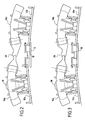
- FIG. 1 partially represents a nozzle 10 with a variable turbomachine section according to the invention.
- the nozzle X-X axis comprises in particular a plurality of controlled movable flaps 12a, 12b and follower movable flaps 13 which are mounted on a downstream end of an annular casing 14 of the turbine engine centered on the axis X-X.
- the controlled flaps 12a, 12b and followers 13 thus form a ring.
- the controlled movable flaps 12a, 12b are actuated directly by a control system so as to modify the profile of the primary flow (i.e. the ejection section) of the turbomachine.
- the control system of the controlled flaps 12a, 12b comprises control levers 16a, 16b each associated with a respective movable flap 12a, 12b and at least one actuating jack 18 of the control levers.
- Each control lever 16a, 16b is attached to the movable flap 12a, 12b that it controls.
- a single jack 18 allows to operate both control levers 16a, 16b.
- the jack 18 directly actuates a first control lever, called a controlled lever 16a, and indirectly a second control lever, called a follower lever 16b, via a transmission link 20 of the clevis type. rotulante connecting the follower lever 16b to the controlled lever 16a.
- control system of the movable shutters comprises as many controlled control levers 16a as levers 16b.
- the nozzle is composed for example of a ring of ten controlled flaps 12a, 12b, five jacks 18 are then sufficient to operate all of these movable flaps.
- the follower flaps 13 are arranged radially inside the controlled flaps 12a, 12b and rest on the adjacent controlled flaps. They are thus intended to ensure the continuity and sealing of the primary stream during the operation of the nozzle and regardless of its opening section.
- the nozzle also has a plurality of supports 22 for each control lever 16a, 16b.
- Such supports 22 are in the form of a pair of arms or splints 22a, 22b substantially parallel and extending along the axis X-X of the nozzle.
- These arms 22a, 22b are fixed on the one hand to the casing 14 at their upstream end, and on the other hand to the control levers 16a, 16b at their downstream end by coils 24.
- FIG. 1 and 2 show in different views the nozzle 10 as described above in a stopped state (that is to say, no operation or at rest).
- the flaps 12b associated with the follower control levers 16b have a radial offset ⁇ (FIG. 2) with respect to the flaps 12a associated with the controlled levers 16a.
- the radial offset ⁇ at the stop of the nozzle of the flaps 12b associated with the follower control levers 16b with respect to the other flaps 12a is directed towards the interior of the nozzle 10 .
- the flaps 12b associated with the follower control levers 16b are located on a smaller diameter than the one on which the flaps 12a associated with the controlled levers 16a are located.
- the follower flap 13 disposed between the adjacent flaps 12a and 12b shown in these FIGS. 1 and 2 is supported only on the flap 12b associated with the lever of FIG. follower command 16b. This is due to the fact that this flap 12b is on a diameter smaller than that on which the flap 12a adjacent is located.
- FIG 3 shows a front view of the nozzle 10 in operation (this operation may for example correspond to the "full gas” mode).
- control lever supports 22 and the casing 14 do not deform in the manner according to whether they comprise a jack or not, an offset is created at the position of the coils 24.
- the radial offset ⁇ applied to the flaps 12b of the nozzle associated with the follower levers 16b is calculated so that in operation, the flaps 12b of the nozzle are found on the same diameter as the flaps 12a associated with the controlled levers 16a.
- a radial offset may be of the order of 10 to 15 mm approximately.
- the radial offset ⁇ of the flaps 12b associated with the follower control levers 16b is achieved by modifying the machining of the follower levers 16b.
- FIG. 4 shows a controlled lever 16a (in solid lines) and a follower lever 16b (in dotted lines). These control levers 16a, 16b are each provided at their opposite angular ends with orifices 26a, 26b (or barrels) for fixing the rotary clevises forming the transmission links.
- these orifices 26a, 26b are machined in a different manner in order to give the flaps associated with the follower levers the required radial offset.
Landscapes
- Engineering & Computer Science (AREA)
- Chemical & Material Sciences (AREA)
- Combustion & Propulsion (AREA)
- Mechanical Engineering (AREA)
- General Engineering & Computer Science (AREA)
- Control Of Turbines (AREA)
- Structures Of Non-Positive Displacement Pumps (AREA)
- Nozzles (AREA)
Applications Claiming Priority (1)
| Application Number | Priority Date | Filing Date | Title |
|---|---|---|---|
| FR0411574A FR2877402B1 (fr) | 2004-10-29 | 2004-10-29 | Tuyere a section variable de turbomachine |
Publications (2)
| Publication Number | Publication Date |
|---|---|
| EP1653073A1 true EP1653073A1 (de) | 2006-05-03 |
| EP1653073B1 EP1653073B1 (de) | 2007-12-12 |
Family
ID=34950443
Family Applications (1)
| Application Number | Title | Priority Date | Filing Date |
|---|---|---|---|
| EP05292149A Expired - Lifetime EP1653073B1 (de) | 2004-10-29 | 2005-10-13 | Schubdüse mit veränderlichem Querschnitt für Turbomaschine |
Country Status (4)
| Country | Link |
|---|---|
| US (1) | US7520135B2 (de) |
| EP (1) | EP1653073B1 (de) |
| FR (1) | FR2877402B1 (de) |
| RU (1) | RU2378522C2 (de) |
Families Citing this family (4)
| Publication number | Priority date | Publication date | Assignee | Title |
|---|---|---|---|---|
| EP3008322B1 (de) * | 2013-06-14 | 2022-03-09 | Saab Ab | Formveränderliche abgasdüse für ein düsentriebwerk und verfahren zur formänderung der düse |
| EP3008320B1 (de) * | 2013-06-14 | 2020-07-29 | Saab Ab | Konvergent-divergente abgasdüse mit variabler geometrie für ein strahltriebwerk und verfahren zur änderung der düse |
| EP3008321B1 (de) * | 2013-06-14 | 2018-11-14 | Saab AB | Variierbare abgasdüse für ein düsentriebwerk und verfahren zur änderung der düse |
| CN112682214A (zh) * | 2020-12-28 | 2021-04-20 | 中国航发沈阳发动机研究所 | 一种轴对称可调收扩喷管内流道平衡协调结构 |
Citations (3)
| Publication number | Priority date | Publication date | Assignee | Title |
|---|---|---|---|---|
| JP2003056404A (ja) * | 2001-08-16 | 2003-02-26 | Ishikawajima Harima Heavy Ind Co Ltd | ジェットエンジン用排気ノズル |
| EP1333172A1 (de) * | 2002-01-31 | 2003-08-06 | Snecma Moteurs | Kühlsystem für eine Nachbrennerdüse in einer Turbomaschine |
| EP1503068A1 (de) * | 2003-07-08 | 2005-02-02 | Snecma Moteurs | Nachgiebige Klappe für eine Austrittsdüse einer Turbomaschine mit variablem Querschnitt |
Family Cites Families (7)
| Publication number | Priority date | Publication date | Assignee | Title |
|---|---|---|---|---|
| BE525114A (de) * | 1952-12-16 | |||
| GB1255010A (en) * | 1968-05-08 | 1971-11-24 | Rolls Royce | Fluid flow control apparatus |
| FR2030532A5 (de) * | 1969-07-03 | 1970-11-13 | Snecma | |
| SU1009150A1 (ru) * | 1980-04-01 | 1996-08-20 | М.В. Барамзин | Регулируемое сверхзвуковое сопло газотурбинного двигателя |
| SU1246671A1 (ru) * | 1984-11-05 | 1996-01-10 | М.В. Барамзин | Сверхзвуковое регулируемое сопло турбореактивного двигателя |
| FR2617910A1 (fr) * | 1987-07-08 | 1989-01-13 | Snecma | Tuyere axisymetrique de turboreacteur convergente divergente |
| US5232158A (en) * | 1992-08-11 | 1993-08-03 | United Technologies Corporation | Convergent/divergent nozzle with seal centering |
-
2004
- 2004-10-29 FR FR0411574A patent/FR2877402B1/fr not_active Expired - Fee Related
-
2005
- 2005-10-13 EP EP05292149A patent/EP1653073B1/de not_active Expired - Lifetime
- 2005-10-13 US US11/248,330 patent/US7520135B2/en active Active
- 2005-10-28 RU RU2005133377/06A patent/RU2378522C2/ru active
Patent Citations (3)
| Publication number | Priority date | Publication date | Assignee | Title |
|---|---|---|---|---|
| JP2003056404A (ja) * | 2001-08-16 | 2003-02-26 | Ishikawajima Harima Heavy Ind Co Ltd | ジェットエンジン用排気ノズル |
| EP1333172A1 (de) * | 2002-01-31 | 2003-08-06 | Snecma Moteurs | Kühlsystem für eine Nachbrennerdüse in einer Turbomaschine |
| EP1503068A1 (de) * | 2003-07-08 | 2005-02-02 | Snecma Moteurs | Nachgiebige Klappe für eine Austrittsdüse einer Turbomaschine mit variablem Querschnitt |
Non-Patent Citations (1)
| Title |
|---|
| PATENT ABSTRACTS OF JAPAN vol. 2003, no. 06 3 June 2003 (2003-06-03) * |
Also Published As
| Publication number | Publication date |
|---|---|
| RU2378522C2 (ru) | 2010-01-10 |
| FR2877402A1 (fr) | 2006-05-05 |
| EP1653073B1 (de) | 2007-12-12 |
| US20060090470A1 (en) | 2006-05-04 |
| US7520135B2 (en) | 2009-04-21 |
| FR2877402B1 (fr) | 2007-05-11 |
| RU2005133377A (ru) | 2007-05-10 |
Similar Documents
| Publication | Publication Date | Title |
|---|---|---|
| CA2594753C (fr) | Tuyere d'ejection des gaz pour turbomachine a double flux ayant une section d'ejection ou de col variable par deplacement du capot secondaire | |
| FR2745036A1 (fr) | Inverseur de poussee de turboreacteur a portes associees a un panneau amont | |
| EP3415749B1 (de) | Gondel mit schubumkehrsystem, das begrenzte aerodynamische störungen aufweist | |
| EP1731839A2 (de) | Vorrichtung zum Anbringen einer Einspritzungvorrichtung am Boden einer Turbinenbrennkammer und Verfahren zum Anbringen | |
| FR3068081A1 (fr) | Systeme d'inverseur de poussee presentant des perturbations aerodynamiques limitees | |
| WO2008145939A2 (fr) | Dispositif de securite compact a declenchement automatique pour controler le debit d'un fluide. | |
| WO1997002419A1 (fr) | Inverseur de poussee de turboreacteur a une coquille | |
| EP0111436B1 (de) | Düse mit veränderlichem Querschnitt für einen Turboreaktor und Flugzeug mit einer solchen Ausrüstung | |
| WO2020007847A1 (fr) | Turbomachine pour aeronef comportant une pluralite de vannes de decharge variable et procede de commande | |
| WO2012059677A2 (fr) | Inverseur de poussee pour turboreacteur d'aeronef, a nombre d'actionneurs reduit | |
| EP1653073B1 (de) | Schubdüse mit veränderlichem Querschnitt für Turbomaschine | |
| CA2780299A1 (fr) | Ensemble arriere de nacelle pour turboreacteur | |
| CA2311259C (fr) | Avion comportant un train d'atterrissage a detachement en cas d'accident | |
| EP0576355B1 (de) | Umschaltlufteinlassklappen für ein Kombitriebwerk mit zwei unterschiedlichen Betriebsweisen | |
| EP0299832A1 (de) | Rotationssymmetrische konvergente/divergente Schubdüse für Strahltriebwerke | |
| WO2018189442A1 (fr) | Lubrification pour train d'engrenages épicycloïdal | |
| FR2882577A1 (fr) | Dispositif de reglage du centrage d'un anneau de synchronisation de commande d'aubes pivotantes de turbomachine | |
| EP0685388B1 (de) | Mechanische Vorrichtung für ein Ausstossgerät mit einem beweglichen Kolben für Hin- und Herbewegung | |
| EP3841022B1 (de) | Vorrichtung und verfahren zur handhabung einer flugzeugantriebsanordnung | |
| EP4392655A1 (de) | Umkehrer mit beweglichen kaskaden für eine flugzeugantriebsanordnung mit einem system zur begrenzung der biegung eines aktuators des umkehrers | |
| EP1674707B1 (de) | Düse mit veränderlichem Querschnitt mit einstückiger Steuerhebelhalterung für eine Turbomaschine | |
| FR2950947A1 (fr) | Vanne destinee, notamment, a etre implantee dans un circuit d'admission d'air d'un moteur thermique | |
| EP4283110B1 (de) | Leitungsanordnung mit mitteln zur halterung von leitungen und motor damit | |
| EP1621751A1 (de) | Konvergente Schubdüse eines Strahltriebwerks | |
| FR2907853A1 (fr) | Tuyere d'ejection des gaz pour turbomachine a double flux ayant une section d'ejection ou de col variable par deploiement de creneaux |
Legal Events
| Date | Code | Title | Description |
|---|---|---|---|
| PUAI | Public reference made under article 153(3) epc to a published international application that has entered the european phase |
Free format text: ORIGINAL CODE: 0009012 |
|
| 17P | Request for examination filed |
Effective date: 20051019 |
|
| AK | Designated contracting states |
Kind code of ref document: A1 Designated state(s): AT BE BG CH CY CZ DE DK EE ES FI FR GB GR HU IE IS IT LI LT LU LV MC NL PL PT RO SE SI SK TR |
|
| AX | Request for extension of the european patent |
Extension state: AL BA HR MK YU |
|
| AKX | Designation fees paid |
Designated state(s): FR GB SE |
|
| REG | Reference to a national code |
Ref country code: DE Ref legal event code: 8566 |
|
| GRAP | Despatch of communication of intention to grant a patent |
Free format text: ORIGINAL CODE: EPIDOSNIGR1 |
|
| GRAS | Grant fee paid |
Free format text: ORIGINAL CODE: EPIDOSNIGR3 |
|
| GRAA | (expected) grant |
Free format text: ORIGINAL CODE: 0009210 |
|
| AK | Designated contracting states |
Kind code of ref document: B1 Designated state(s): FR GB SE |
|
| REG | Reference to a national code |
Ref country code: GB Ref legal event code: FG4D Free format text: NOT ENGLISH |
|
| GBT | Gb: translation of ep patent filed (gb section 77(6)(a)/1977) |
Effective date: 20080305 |
|
| REG | Reference to a national code |
Ref country code: SE Ref legal event code: TRGR |
|
| PLBE | No opposition filed within time limit |
Free format text: ORIGINAL CODE: 0009261 |
|
| STAA | Information on the status of an ep patent application or granted ep patent |
Free format text: STATUS: NO OPPOSITION FILED WITHIN TIME LIMIT |
|
| 26N | No opposition filed |
Effective date: 20080915 |
|
| REG | Reference to a national code |
Ref country code: FR Ref legal event code: PLFP Year of fee payment: 11 |
|
| REG | Reference to a national code |
Ref country code: FR Ref legal event code: PLFP Year of fee payment: 12 |
|
| REG | Reference to a national code |
Ref country code: FR Ref legal event code: PLFP Year of fee payment: 13 |
|
| REG | Reference to a national code |
Ref country code: FR Ref legal event code: CD Owner name: SAFRAN AIRCRAFT ENGINES Effective date: 20170717 |
|
| REG | Reference to a national code |
Ref country code: FR Ref legal event code: PLFP Year of fee payment: 14 |
|
| PGFP | Annual fee paid to national office [announced via postgrant information from national office to epo] |
Ref country code: GB Payment date: 20240919 Year of fee payment: 20 |
|
| PGFP | Annual fee paid to national office [announced via postgrant information from national office to epo] |
Ref country code: FR Payment date: 20240919 Year of fee payment: 20 |
|
| PGFP | Annual fee paid to national office [announced via postgrant information from national office to epo] |
Ref country code: SE Payment date: 20240919 Year of fee payment: 20 |
|
| REG | Reference to a national code |
Ref country code: GB Ref legal event code: PE20 Expiry date: 20251012 |
|
| REG | Reference to a national code |
Ref country code: SE Ref legal event code: EUG |