EP1503068A1 - Nachgiebige Klappe für eine Austrittsdüse einer Turbomaschine mit variablem Querschnitt - Google Patents
Nachgiebige Klappe für eine Austrittsdüse einer Turbomaschine mit variablem Querschnitt Download PDFInfo
- Publication number
- EP1503068A1 EP1503068A1 EP04291704A EP04291704A EP1503068A1 EP 1503068 A1 EP1503068 A1 EP 1503068A1 EP 04291704 A EP04291704 A EP 04291704A EP 04291704 A EP04291704 A EP 04291704A EP 1503068 A1 EP1503068 A1 EP 1503068A1
- Authority
- EP
- European Patent Office
- Prior art keywords
- boxes
- transverse
- flexible
- follower flap
- edges
- Prior art date
- Legal status (The legal status is an assumption and is not a legal conclusion. Google has not performed a legal analysis and makes no representation as to the accuracy of the status listed.)
- Granted
Links
- 239000002184 metal Substances 0.000 claims description 6
- 239000000463 material Substances 0.000 claims description 4
- 238000007789 sealing Methods 0.000 description 13
- 238000006073 displacement reaction Methods 0.000 description 5
- 238000011144 upstream manufacturing Methods 0.000 description 4
- 210000003462 vein Anatomy 0.000 description 4
- 230000000694 effects Effects 0.000 description 3
- 238000012423 maintenance Methods 0.000 description 3
- 239000007789 gas Substances 0.000 description 2
- 238000009825 accumulation Methods 0.000 description 1
- 230000003042 antagnostic effect Effects 0.000 description 1
- 230000006735 deficit Effects 0.000 description 1
- 230000001934 delay Effects 0.000 description 1
- 238000010586 diagram Methods 0.000 description 1
- 238000010494 dissociation reaction Methods 0.000 description 1
- 230000005593 dissociations Effects 0.000 description 1
- 238000004519 manufacturing process Methods 0.000 description 1
- 230000000284 resting effect Effects 0.000 description 1
- 239000003351 stiffener Substances 0.000 description 1
Images



Classifications
-
- F—MECHANICAL ENGINEERING; LIGHTING; HEATING; WEAPONS; BLASTING
- F02—COMBUSTION ENGINES; HOT-GAS OR COMBUSTION-PRODUCT ENGINE PLANTS
- F02K—JET-PROPULSION PLANTS
- F02K1/00—Plants characterised by the form or arrangement of the jet pipe or nozzle; Jet pipes or nozzles peculiar thereto
- F02K1/06—Varying effective area of jet pipe or nozzle
- F02K1/12—Varying effective area of jet pipe or nozzle by means of pivoted flaps
-
- F—MECHANICAL ENGINEERING; LIGHTING; HEATING; WEAPONS; BLASTING
- F02—COMBUSTION ENGINES; HOT-GAS OR COMBUSTION-PRODUCT ENGINE PLANTS
- F02K—JET-PROPULSION PLANTS
- F02K1/00—Plants characterised by the form or arrangement of the jet pipe or nozzle; Jet pipes or nozzles peculiar thereto
- F02K1/06—Varying effective area of jet pipe or nozzle
- F02K1/12—Varying effective area of jet pipe or nozzle by means of pivoted flaps
- F02K1/1207—Varying effective area of jet pipe or nozzle by means of pivoted flaps of one series of flaps hinged at their upstream ends on a fixed structure
-
- F—MECHANICAL ENGINEERING; LIGHTING; HEATING; WEAPONS; BLASTING
- F02—COMBUSTION ENGINES; HOT-GAS OR COMBUSTION-PRODUCT ENGINE PLANTS
- F02K—JET-PROPULSION PLANTS
- F02K1/00—Plants characterised by the form or arrangement of the jet pipe or nozzle; Jet pipes or nozzles peculiar thereto
- F02K1/78—Other construction of jet pipes
- F02K1/80—Couplings or connections
-
- F—MECHANICAL ENGINEERING; LIGHTING; HEATING; WEAPONS; BLASTING
- F02—COMBUSTION ENGINES; HOT-GAS OR COMBUSTION-PRODUCT ENGINE PLANTS
- F02K—JET-PROPULSION PLANTS
- F02K1/00—Plants characterised by the form or arrangement of the jet pipe or nozzle; Jet pipes or nozzles peculiar thereto
- F02K1/78—Other construction of jet pipes
- F02K1/80—Couplings or connections
- F02K1/805—Sealing devices therefor, e.g. for movable parts of jet pipes or nozzle flaps
Definitions
- the present invention relates to the general field of turbomachines variable section nozzles and it concerns more particularly the nozzles constituted by a ring of flaps.
- FIG. 7 Conventional nozzle architecture with variable cross section 10 of turbomachine is illustrated in Figure 7.
- nozzles with variable section consisting of a crown of shutters consist of both shutters controlled 12, 14 and follower flaps 16.
- control means so as to modify the profile of the primary flow the turbomachine engine (i.e. the ejection section or sections according to whether it is a simple convergent or a nozzle converging / diverging).
- these control means comprise a control cylinder 18 associated to a more or less complex kinematics using levers 20, swiveling linkages 22 or a ring, cams and rollers for example.
- the follower flaps arranged radially inside the shutters ordered are based on the adjacent controlled shutters of on both sides of their longitudinal edges and thus ensure continuity (and watertightness) of the primary vein (hence the name of sealing flaps also given to these follower flaps) during the operation of the nozzle and this regardless of its section opening.
- the present invention therefore aims to overcome these disadvantages by proposing a follower flap structure flexible enough to bridge gaps between shutters orders.
- An object of the invention is also to produce a component flexible follower able to support loads important in pressure and temperature.
- a flexible follower flap for a nozzle turbomachine variable section interposed between two shutters adjacent orders against which it is held by fastening means characterized in that it comprises a plurality of independent transverse boxes mounted side by side in a support plate, the boxes being in contact by their edges longitudinals raised and maintained in the support plate by their side edges that are enclosed in longitudinal edges of the support plate.
- the longitudinal edges of the support plate enclosing the edges lateral of the caissons define a support zone for the shutters adjacent controls and they have notches for keep in position the transverse boxes, each notch receiving the ends of the raised longitudinal edges of two adjacent boxes.
- a box of said plurality of boxes transverse bars further comprises a transverse bar of holding intended to support the follower flap in the rest position.
- This holding bar constitutes the terminal transverse arm of a short post extending radially from a longitudinal edge said transverse box.
- the transverse box is an end box the shutter and the support plate is formed of a metal plate in one relatively flexible material and resistant to high temperature
- the invention also relates to a nozzle with a variable section turbomachine comprising a plurality of flexible follower flaps as mentioned above.
- Figure 1 illustrates in perspective a shutter structure follower according to the present invention.
- This qualified component of flexible because of its possibility of deformation comprises several caissons 30 independent units held side by side in a support plate 32 also sealing the vein of hot gases.
- the blind follower is connected to two adjacent controlled flaps by two holding bars, one upstream 34 disposed substantially at level of its theoretical axis of articulation and intended to position the follower flap in the nozzle and the other downstream 36 arranged substantially at its free end, opposite its axis of articulation theoretical, and intended to hold this flap in rest position (engine stopped).
- Each box 30 has a rectangular shape with two longitudinal edges (or wings) 30A (longer) relieves providing a stiffener function for the box and two side edges 30B (shorter length) folded intended to come fit into the sealing plate.
- the number of boxes and their stiffness depend on the characteristics sought for the nozzle and in particular they are optimized according to the pressure and the temperature on the shutter, its dimensions, the materials used, the cantilever to fill and height available so that the ends longitudinal edges of the caissons do not interfere with the shutters orders.
- the end casing 38 integrates the bar 36 of downstream maintenance of the follower flap.
- the longitudinal edge external 38A of this box is extended in its center by a short vertical post 38B extending radially outwardly of the nozzle and terminated by a curved transverse arm 38C forming a bar keeping.
- This holding arm has a length greater than the width of the follower flap so that its two ends 38D can come into contact on the two shutters ordered surrounding this follower flap.
- the sealing plate is formed of a metal plate in one relatively flexible material and resistant to high temperature (greater than 1000 ° C) of rectangular shape and dimensions compatible with the free space to be bridged between two shutters orders. More precisely, the follower flap has a width greater than that of this free space, so as to create a zone of overlap at each of its two longitudinal edges corresponding to a support zone of the follower flap on the flap ordered.
- the longitudinal edges 32A of the sealing plate are bent (turned) to grip the side edges folded 30B boxes 30 and they have notches 32B distributed regularly to receive the ends of the longitudinal edges 30A of two adjacent boxes and thus ensure their maintenance spouse.
- the longitudinal edges 30A contiguous two caissons adjacent areas that ensure the rigidity of these boxes can slide freely on each other.
- This flap configuration allows complete dissociation functions. Indeed, on the one hand the caissons constitute the structure of the shutter and ensures its mechanical strength vis-à-vis the efforts pressure. When the shutter is twisted, the boxes move in relation to each other and undergo very little deformation. Sure the only effect of the displacements imposed on the shutter so there is almost no stress generated in the boxes. On the other hand, the sheet simply ensures the seal between the boxes in improving the geometry of the motor vein. She permits incidentally to maintain the boxes between them on the edges without ensuring any structural role.
- the holding bar upstream 34 whose attachment to the sealing plate 32 is effected by for example, by means of at least one screw 40.
- this support bar is fixed on a metal bridge-shaped support 42 welded to a end to the sealing plate and coming to the other end in support against a longitudinal edge 44A of a first box 44 of the shutter follower, in the manner of a clamp.
- any other means removable allowing this quick attachment of the flap in the nozzle is possible.
- Figure 2 shows the attachment of the follower flap to one of the two controlled shutters that are adjacent to it. It is carried out at the level of the upstream retaining bar 34 in the form of hanger having each end 34A having a cylindrical lug is held in position between two studs 46 arranged on the edge external longitudinal component of the controlled flap and which frame this end to limit the lateral displacement (along the axis of the nozzle) while allowing it to move in two degrees of freedom (in rotation and in longitudinal translation), and on the other hand level of the downstream retaining bar 36, each end 36A simply rest on this outer longitudinal edge of the shutter ordered.
- the caissons support the entire sealing plate and the efforts supported by the shutter can then be important.
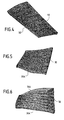
- FIGs 3 and 3A illustrate the various stages of assembly a follower pane.
- the boxes are made individually from sheet metal plates that are folded to form the folded edges and the caissons, the end box being shaped to integrate the downstream support bar 36.
- the sealing plate is as for it elaborated from a plate of sheet whose edges longitudinal sections are cut and folded partially to receive and guide the various caissons intended to form the shutter. Once these are slid one by one into the sheet, the ends of the edges lengths of the various boxes coming from the notches, the folding of the longitudinal edges is completed to ensure a perfect fixing these boxes, as shown in Figure 3A.
- the whole can to be mounted between two controlled shutters, the hanging of these shutters being then ensured by the fixing of the holding bar upstream.
- the flexible follower flap of the invention promotes the moving between boxes to avoid stress in the rooms of the shutter. It is the juxtaposition of the caissons that allows them to be free to move between them while being contiguous. Prison sealing is only clamped on its longitudinal edges. Subject to high pressure, each box comes to rely on flaps and the sheet then weakly loaded on the caissons.
Landscapes
- Engineering & Computer Science (AREA)
- Chemical & Material Sciences (AREA)
- Combustion & Propulsion (AREA)
- Mechanical Engineering (AREA)
- General Engineering & Computer Science (AREA)
- Supercharger (AREA)
- Control Of Turbines (AREA)
- Turbine Rotor Nozzle Sealing (AREA)
- Making Paper Articles (AREA)
- Lift Valve (AREA)
- Gasket Seals (AREA)
Applications Claiming Priority (2)
| Application Number | Priority Date | Filing Date | Title |
|---|---|---|---|
| FR0308311 | 2003-07-08 | ||
| FR0308311A FR2857414B1 (fr) | 2003-07-08 | 2003-07-08 | Volet souple de tuyere a section variable de turbomachine |
Publications (2)
| Publication Number | Publication Date |
|---|---|
| EP1503068A1 true EP1503068A1 (de) | 2005-02-02 |
| EP1503068B1 EP1503068B1 (de) | 2009-09-09 |
Family
ID=33522840
Family Applications (1)
| Application Number | Title | Priority Date | Filing Date |
|---|---|---|---|
| EP04291704A Expired - Lifetime EP1503068B1 (de) | 2003-07-08 | 2004-07-06 | Nachgiebige Klappe für eine Austrittsdüse einer Turbomaschine mit variablem Querschnitt |
Country Status (10)
| Country | Link |
|---|---|
| US (1) | US7013650B2 (de) |
| EP (1) | EP1503068B1 (de) |
| JP (1) | JP2005030396A (de) |
| KR (1) | KR20050006073A (de) |
| CN (1) | CN1576519A (de) |
| CA (1) | CA2472878A1 (de) |
| DE (1) | DE602004023035D1 (de) |
| ES (1) | ES2332455T3 (de) |
| FR (1) | FR2857414B1 (de) |
| RU (1) | RU2341673C2 (de) |
Cited By (3)
| Publication number | Priority date | Publication date | Assignee | Title |
|---|---|---|---|---|
| EP1653073A1 (de) * | 2004-10-29 | 2006-05-03 | Snecma | Schubdüse mit veränderlichem Querschnitt für Turbomaschine |
| EP1674707A1 (de) * | 2004-10-26 | 2006-06-28 | Snecma | Düse mit veränderlichem Querschnitt mit einstückiger Steuerhebelhalterung für eine Turbomaschine |
| FR2970519A1 (fr) * | 2011-01-14 | 2012-07-20 | Snecma | Volet interne commande, tuyere le comprenant, turbomachine d'aeronef comprenant une telle tuyere |
Families Citing this family (8)
| Publication number | Priority date | Publication date | Assignee | Title |
|---|---|---|---|---|
| US7458221B1 (en) * | 2003-10-23 | 2008-12-02 | The United States Of America As Represented By The Administrator Of The National Aeronautics And Space Administration | Variable area nozzle including a plurality of convexly vanes with a crowned contour, in a vane to vane sealing arrangement and with nonuniform lengths |
| US7302793B2 (en) * | 2003-10-29 | 2007-12-04 | General Electric Company | Methods and apparatus to reduce turbine engine nozzle basesheet stresses |
| US7721549B2 (en) * | 2007-02-08 | 2010-05-25 | United Technologies Corporation | Fan variable area nozzle for a gas turbine engine fan nacelle with cam drive ring actuation system |
| US8122722B2 (en) * | 2008-02-29 | 2012-02-28 | General Electric Company | Exhaust nozzle seal with segmented basesheet disposed between side rails |
| US8156745B2 (en) * | 2008-02-29 | 2012-04-17 | General Electric Company | Exhaust nozzle seal with segmented basesheet |
| US20110147533A1 (en) * | 2009-12-21 | 2011-06-23 | Honeywell International Inc. | Morphing ducted fan for vertical take-off and landing vehicle |
| US8549834B2 (en) | 2010-10-21 | 2013-10-08 | United Technologies Corporation | Gas turbine engine with variable area fan nozzle |
| CN112682214A (zh) * | 2020-12-28 | 2021-04-20 | 中国航发沈阳发动机研究所 | 一种轴对称可调收扩喷管内流道平衡协调结构 |
Citations (7)
| Publication number | Priority date | Publication date | Assignee | Title |
|---|---|---|---|---|
| US4637550A (en) * | 1985-10-01 | 1987-01-20 | The United States Of America As Represented By The Secretary Of The Air Force | Dual material exhaust nozzle flap |
| US4662566A (en) * | 1985-12-02 | 1987-05-05 | United Technologies Corporation | Louvered seal flap for flap-type nozzle |
| US5000386A (en) * | 1989-07-03 | 1991-03-19 | General Electric Company | Exhaust flaps |
| US5215257A (en) * | 1992-07-16 | 1993-06-01 | United Technologies Corporation | Divergent seal arrangement for a convergent/divergent nozzle |
| EP0644325A1 (de) * | 1993-09-21 | 1995-03-22 | Sener, Ingenieria Y Sistemas, S.A. | Abgasdüse für eine Gasturbine |
| EP0715067A2 (de) * | 1994-12-02 | 1996-06-05 | United Technologies Corporation | Dichtstreifen für eine Schubdüse |
| US5680755A (en) * | 1995-09-25 | 1997-10-28 | General Electric Company | Convertible ejector selectively cooled thrust vectoring exhaust nozzle |
Family Cites Families (19)
| Publication number | Priority date | Publication date | Assignee | Title |
|---|---|---|---|---|
| US4690330A (en) * | 1985-12-02 | 1987-09-01 | United Technologies Corporation | Louvered seal flap edge stiffener |
| US5039014A (en) * | 1989-04-11 | 1991-08-13 | General Electric Company | Axisymmetric vectoring exhaust nozzle seal |
| US4994660A (en) * | 1989-04-11 | 1991-02-19 | Hitachi, Ltd. | Axisymmetric vectoring exhaust nozzle |
| US5076496A (en) * | 1990-02-05 | 1991-12-31 | General Electric Company | Exhaust nozzle flap seal |
| US5261605A (en) * | 1990-08-23 | 1993-11-16 | United Technologies Corporation | Axisymmetric nozzle with gimbled unison ring |
| EP0723075B1 (de) * | 1991-05-16 | 2001-11-21 | General Electric Company | Hitzeschild für achsymmetrische schwenkbare Schubdüse |
| US5215256A (en) * | 1992-07-16 | 1993-06-01 | Barcza W Kevin | Flap hinge arrangement for a convergent/divergent nozzle |
| US5238189A (en) * | 1992-07-16 | 1993-08-24 | United Technologies Corporation | Convergent-to-divergent seal hinge for a convergent/divergent nozzle |
| US5269467A (en) * | 1992-08-03 | 1993-12-14 | General Electric Company | Vectoring exhaust nozzle seal and flap retaining apparatus |
| US5484105A (en) * | 1994-07-13 | 1996-01-16 | General Electric Company | Cooling system for a divergent section of a nozzle |
| US5683034A (en) * | 1995-05-22 | 1997-11-04 | United Technologies Corporation | Engine exhaust nozzle seal |
| US5893518A (en) * | 1995-11-30 | 1999-04-13 | United Technologies Corporation | Attachment means for flaps of variable exhaust nozzle |
| US5839663A (en) * | 1996-07-23 | 1998-11-24 | United Technologies Corporation | Gas turbine exhaust nozzle flap and flap seal apparatus |
| US5797544A (en) * | 1996-09-27 | 1998-08-25 | United Technologies Corporation | C/D nozzle with synchronizing ring link suspension |
| US5813611A (en) * | 1996-09-27 | 1998-09-29 | United Technologies Corporation | Compact pressure balanced fulcrum-link nozzle |
| DE69725432T2 (de) * | 1997-06-16 | 2004-08-19 | Industria De Turbo Propulsores S.A., Zamudio | Befestigungsvorrichtung für eine divergierende Master-Düsenklappe einer Schubüse mit veränderlicher Geometrie |
| EP0899428B1 (de) * | 1997-08-28 | 2003-01-02 | Industria de Turbo Propulsores S.A. | Zentriervorrichtung mit gekreuzten Querverbindungen für die ungesteuerten Klappen einer verstellbaren convergent-divergenten-Schubdüse |
| US6745570B2 (en) * | 2002-02-01 | 2004-06-08 | General Electric Co. | Methods and apparatus for sealing gas turbine engine nozzles using a flap system |
| US6658854B2 (en) * | 2002-02-01 | 2003-12-09 | General Electric Co. | Methods and apparatus for retaining gas turbine engine nozzle basesheets |
-
2003
- 2003-07-08 FR FR0308311A patent/FR2857414B1/fr not_active Expired - Fee Related
-
2004
- 2004-06-29 CA CA002472878A patent/CA2472878A1/fr not_active Abandoned
- 2004-07-05 RU RU2004120250/06A patent/RU2341673C2/ru active
- 2004-07-05 JP JP2004197832A patent/JP2005030396A/ja not_active Withdrawn
- 2004-07-06 ES ES04291704T patent/ES2332455T3/es not_active Expired - Lifetime
- 2004-07-06 EP EP04291704A patent/EP1503068B1/de not_active Expired - Lifetime
- 2004-07-06 DE DE602004023035T patent/DE602004023035D1/de not_active Expired - Lifetime
- 2004-07-07 KR KR1020040052723A patent/KR20050006073A/ko not_active Withdrawn
- 2004-07-07 US US10/885,479 patent/US7013650B2/en not_active Expired - Lifetime
- 2004-07-08 CN CNA200410063380XA patent/CN1576519A/zh active Pending
Patent Citations (7)
| Publication number | Priority date | Publication date | Assignee | Title |
|---|---|---|---|---|
| US4637550A (en) * | 1985-10-01 | 1987-01-20 | The United States Of America As Represented By The Secretary Of The Air Force | Dual material exhaust nozzle flap |
| US4662566A (en) * | 1985-12-02 | 1987-05-05 | United Technologies Corporation | Louvered seal flap for flap-type nozzle |
| US5000386A (en) * | 1989-07-03 | 1991-03-19 | General Electric Company | Exhaust flaps |
| US5215257A (en) * | 1992-07-16 | 1993-06-01 | United Technologies Corporation | Divergent seal arrangement for a convergent/divergent nozzle |
| EP0644325A1 (de) * | 1993-09-21 | 1995-03-22 | Sener, Ingenieria Y Sistemas, S.A. | Abgasdüse für eine Gasturbine |
| EP0715067A2 (de) * | 1994-12-02 | 1996-06-05 | United Technologies Corporation | Dichtstreifen für eine Schubdüse |
| US5680755A (en) * | 1995-09-25 | 1997-10-28 | General Electric Company | Convertible ejector selectively cooled thrust vectoring exhaust nozzle |
Cited By (3)
| Publication number | Priority date | Publication date | Assignee | Title |
|---|---|---|---|---|
| EP1674707A1 (de) * | 2004-10-26 | 2006-06-28 | Snecma | Düse mit veränderlichem Querschnitt mit einstückiger Steuerhebelhalterung für eine Turbomaschine |
| EP1653073A1 (de) * | 2004-10-29 | 2006-05-03 | Snecma | Schubdüse mit veränderlichem Querschnitt für Turbomaschine |
| FR2970519A1 (fr) * | 2011-01-14 | 2012-07-20 | Snecma | Volet interne commande, tuyere le comprenant, turbomachine d'aeronef comprenant une telle tuyere |
Also Published As
| Publication number | Publication date |
|---|---|
| KR20050006073A (ko) | 2005-01-15 |
| ES2332455T3 (es) | 2010-02-05 |
| EP1503068B1 (de) | 2009-09-09 |
| US20050022532A1 (en) | 2005-02-03 |
| JP2005030396A (ja) | 2005-02-03 |
| FR2857414B1 (fr) | 2007-06-08 |
| CA2472878A1 (fr) | 2005-01-08 |
| DE602004023035D1 (de) | 2009-10-22 |
| US7013650B2 (en) | 2006-03-21 |
| RU2341673C2 (ru) | 2008-12-20 |
| CN1576519A (zh) | 2005-02-09 |
| RU2004120250A (ru) | 2006-01-10 |
| FR2857414A1 (fr) | 2005-01-14 |
Similar Documents
| Publication | Publication Date | Title |
|---|---|---|
| EP1503068B1 (de) | Nachgiebige Klappe für eine Austrittsdüse einer Turbomaschine mit variablem Querschnitt | |
| EP2204541A1 (de) | Rotorstufe einer einteilig beschaufelten Verdichtertrommel einer axialen Strömungsmaschine und entsprechendes Herstellungsverfahren. | |
| FR2547356A1 (fr) | Joint d'etancheite marginal de volet de tuyere | |
| EP0567392A1 (de) | Ringförmige Bürstendichtung | |
| FR2632357A1 (fr) | Ensemble d'aubes de stator pour turbomoteur | |
| EP2448814A1 (de) | Rumpfelement mit einem rumpfsegment und übergangsvorrichtung | |
| EP3055594B1 (de) | Dichtung für einen schubumkehrer einer turbodüsen-triebwerksgondel | |
| FR2955142A1 (fr) | Amortisseur de vibrations a pion entre talons d'aubes adjacentes en materiau composite d'une roue mobile de turbomachine. | |
| EP2898211A1 (de) | Schubumkehrvorrichtung mit fixer struktur | |
| FR2638783A1 (fr) | Inverseur de poussee notamment pour moteur a reaction d'aeronef | |
| FR2768212A1 (fr) | Joint statique d'etancheite, actionne par la pression | |
| WO2010007311A1 (fr) | Dispositif pour ceinturer une nacelle d'aeronef | |
| FR2760788A1 (fr) | Inverseur de poussee de turboreacteur a portes a structure externe plaquee | |
| EP3947950B1 (de) | Tür für schubumkehrvorrichtung einer flugzeugantriebsanordnung mit einer flexiblen ablenkplatte | |
| FR3018329A1 (fr) | Joint de type bulle integrant au moins une butee rigide | |
| EP2447158A2 (de) | Verkleidung eines Luftfahrzeugs, die mit Mitteln zur Begrenzung der Stauphänomene magnetischer Art ausgestattet ist | |
| FR3070466B1 (fr) | Dispositif d’etancheite pour nacelle de turboreacteur d’aeronef | |
| WO2020094972A1 (fr) | Joint d'étanchéité pour nacelle de turboréacteur d'aéronef | |
| EP2435686B1 (de) | Teil zur Zusammenfügung des beweglichen Teils einer einsetzbaren divergierenden Düse einer Antriebseinheit und Mechanismus für den Einsatz des beweglichen Teils | |
| FR2960021A1 (fr) | Roue mobile de turbomachine munie d'un jonc d'amortissement des vibrations | |
| EP2188178A1 (de) | Triebwerksgondel zum einbau in ein flugzeug | |
| EP1990260B1 (de) | Kotflügel eines Kraftfahrzeuges mit Beleuchtungsanschlägen. | |
| FR3041307A1 (fr) | Organe d’essuie-glace comprenant un capot articule | |
| FR3009543A1 (fr) | Assemblage pour aeronef comprenant un panneau d'acces aux articulations d'un capot de nacelle deplacable par cooperation entre une rampe et un organe d'appui | |
| EP3717766B1 (de) | Schubumkehrer für eine flugzeugtriebwerksgondel, mit einer platte zur vermeidung einer beweglichen lamelle des flügels und gondel im zusammenhang damit |
Legal Events
| Date | Code | Title | Description |
|---|---|---|---|
| PUAI | Public reference made under article 153(3) epc to a published international application that has entered the european phase |
Free format text: ORIGINAL CODE: 0009012 |
|
| 17P | Request for examination filed |
Effective date: 20040716 |
|
| AK | Designated contracting states |
Kind code of ref document: A1 Designated state(s): AT BE BG CH CY CZ DE DK EE ES FI FR GB GR HU IE IT LI LU MC NL PL PT RO SE SI SK TR |
|
| AX | Request for extension of the european patent |
Extension state: AL HR LT LV MK |
|
| RAP1 | Party data changed (applicant data changed or rights of an application transferred) |
Owner name: SNECMA |
|
| AKX | Designation fees paid |
Designated state(s): DE ES FR GB IT SE |
|
| GRAP | Despatch of communication of intention to grant a patent |
Free format text: ORIGINAL CODE: EPIDOSNIGR1 |
|
| GRAS | Grant fee paid |
Free format text: ORIGINAL CODE: EPIDOSNIGR3 |
|
| GRAA | (expected) grant |
Free format text: ORIGINAL CODE: 0009210 |
|
| AK | Designated contracting states |
Kind code of ref document: B1 Designated state(s): DE ES FR GB IT SE |
|
| REG | Reference to a national code |
Ref country code: GB Ref legal event code: FG4D Free format text: NOT ENGLISH |
|
| REF | Corresponds to: |
Ref document number: 602004023035 Country of ref document: DE Date of ref document: 20091022 Kind code of ref document: P |
|
| REG | Reference to a national code |
Ref country code: SE Ref legal event code: TRGR |
|
| REG | Reference to a national code |
Ref country code: ES Ref legal event code: FG2A Ref document number: 2332455 Country of ref document: ES Kind code of ref document: T3 |
|
| PLBE | No opposition filed within time limit |
Free format text: ORIGINAL CODE: 0009261 |
|
| STAA | Information on the status of an ep patent application or granted ep patent |
Free format text: STATUS: NO OPPOSITION FILED WITHIN TIME LIMIT |
|
| 26N | No opposition filed |
Effective date: 20100610 |
|
| PGFP | Annual fee paid to national office [announced via postgrant information from national office to epo] |
Ref country code: ES Payment date: 20120716 Year of fee payment: 9 |
|
| REG | Reference to a national code |
Ref country code: ES Ref legal event code: FD2A Effective date: 20150401 |
|
| PG25 | Lapsed in a contracting state [announced via postgrant information from national office to epo] |
Ref country code: ES Free format text: LAPSE BECAUSE OF NON-PAYMENT OF DUE FEES Effective date: 20130707 |
|
| REG | Reference to a national code |
Ref country code: FR Ref legal event code: PLFP Year of fee payment: 13 |
|
| REG | Reference to a national code |
Ref country code: FR Ref legal event code: PLFP Year of fee payment: 14 |
|
| REG | Reference to a national code |
Ref country code: FR Ref legal event code: PLFP Year of fee payment: 15 |
|
| REG | Reference to a national code |
Ref country code: FR Ref legal event code: CD Owner name: SAFRAN AIRCRAFT ENGINES, FR Effective date: 20170719 |
|
| PGFP | Annual fee paid to national office [announced via postgrant information from national office to epo] |
Ref country code: IT Payment date: 20230620 Year of fee payment: 20 |
|
| PGFP | Annual fee paid to national office [announced via postgrant information from national office to epo] |
Ref country code: SE Payment date: 20230622 Year of fee payment: 20 |
|
| PGFP | Annual fee paid to national office [announced via postgrant information from national office to epo] |
Ref country code: GB Payment date: 20230620 Year of fee payment: 20 |
|
| PGFP | Annual fee paid to national office [announced via postgrant information from national office to epo] |
Ref country code: FR Payment date: 20230724 Year of fee payment: 20 Ref country code: DE Payment date: 20230620 Year of fee payment: 20 |
|
| REG | Reference to a national code |
Ref country code: DE Ref legal event code: R071 Ref document number: 602004023035 Country of ref document: DE |
|
| REG | Reference to a national code |
Ref country code: GB Ref legal event code: PE20 Expiry date: 20240705 |
|
| REG | Reference to a national code |
Ref country code: SE Ref legal event code: EUG |
|
| PG25 | Lapsed in a contracting state [announced via postgrant information from national office to epo] |
Ref country code: GB Free format text: LAPSE BECAUSE OF EXPIRATION OF PROTECTION Effective date: 20240705 |
|
| PG25 | Lapsed in a contracting state [announced via postgrant information from national office to epo] |
Ref country code: GB Free format text: LAPSE BECAUSE OF EXPIRATION OF PROTECTION Effective date: 20240705 |