EP1653098B1 - Procede de fabrication d'une cage de roulement a rouleaux, et cage de roulement a rouleaux - Google Patents
Procede de fabrication d'une cage de roulement a rouleaux, et cage de roulement a rouleaux Download PDFInfo
- Publication number
- EP1653098B1 EP1653098B1 EP04771610A EP04771610A EP1653098B1 EP 1653098 B1 EP1653098 B1 EP 1653098B1 EP 04771610 A EP04771610 A EP 04771610A EP 04771610 A EP04771610 A EP 04771610A EP 1653098 B1 EP1653098 B1 EP 1653098B1
- Authority
- EP
- European Patent Office
- Prior art keywords
- intermediate material
- retainer
- roller bearing
- holes
- forming
- Prior art date
- Legal status (The legal status is an assumption and is not a legal conclusion. Google has not performed a legal analysis and makes no representation as to the accuracy of the status listed.)
- Expired - Lifetime
Links
- 238000004519 manufacturing process Methods 0.000 title claims description 37
- 239000000463 material Substances 0.000 claims description 141
- 239000002184 metal Substances 0.000 claims description 37
- 230000002093 peripheral effect Effects 0.000 claims description 26
- 238000005520 cutting process Methods 0.000 claims description 15
- 230000015572 biosynthetic process Effects 0.000 claims description 10
- 238000003825 pressing Methods 0.000 description 13
- 210000002105 tongue Anatomy 0.000 description 11
- 238000000034 method Methods 0.000 description 7
- 238000010586 diagram Methods 0.000 description 6
- 238000005096 rolling process Methods 0.000 description 3
- 230000000717 retained effect Effects 0.000 description 2
- 238000009966 trimming Methods 0.000 description 2
- 230000006835 compression Effects 0.000 description 1
- 238000007906 compression Methods 0.000 description 1
- 238000010276 construction Methods 0.000 description 1
- 238000007796 conventional method Methods 0.000 description 1
- 238000012986 modification Methods 0.000 description 1
- 230000004048 modification Effects 0.000 description 1
- 230000007935 neutral effect Effects 0.000 description 1
- 238000004080 punching Methods 0.000 description 1
- 238000000926 separation method Methods 0.000 description 1
Images




Classifications
-
- F—MECHANICAL ENGINEERING; LIGHTING; HEATING; WEAPONS; BLASTING
- F16—ENGINEERING ELEMENTS AND UNITS; GENERAL MEASURES FOR PRODUCING AND MAINTAINING EFFECTIVE FUNCTIONING OF MACHINES OR INSTALLATIONS; THERMAL INSULATION IN GENERAL
- F16C—SHAFTS; FLEXIBLE SHAFTS; ELEMENTS OR CRANKSHAFT MECHANISMS; ROTARY BODIES OTHER THAN GEARING ELEMENTS; BEARINGS
- F16C33/00—Parts of bearings; Special methods for making bearings or parts thereof
- F16C33/30—Parts of ball or roller bearings
- F16C33/46—Cages for rollers or needles
- F16C33/467—Details of individual pockets, e.g. shape or roller retaining means
- F16C33/4682—Details of individual pockets, e.g. shape or roller retaining means of the end walls, e.g. interaction with the end faces of the rollers
-
- B—PERFORMING OPERATIONS; TRANSPORTING
- B21—MECHANICAL METAL-WORKING WITHOUT ESSENTIALLY REMOVING MATERIAL; PUNCHING METAL
- B21D—WORKING OR PROCESSING OF SHEET METAL OR METAL TUBES, RODS OR PROFILES WITHOUT ESSENTIALLY REMOVING MATERIAL; PUNCHING METAL
- B21D53/00—Making other particular articles
- B21D53/10—Making other particular articles parts of bearings; sleeves; valve seats or the like
- B21D53/12—Making other particular articles parts of bearings; sleeves; valve seats or the like cages for bearings
-
- F—MECHANICAL ENGINEERING; LIGHTING; HEATING; WEAPONS; BLASTING
- F16—ENGINEERING ELEMENTS AND UNITS; GENERAL MEASURES FOR PRODUCING AND MAINTAINING EFFECTIVE FUNCTIONING OF MACHINES OR INSTALLATIONS; THERMAL INSULATION IN GENERAL
- F16C—SHAFTS; FLEXIBLE SHAFTS; ELEMENTS OR CRANKSHAFT MECHANISMS; ROTARY BODIES OTHER THAN GEARING ELEMENTS; BEARINGS
- F16C23/00—Bearings for exclusively rotary movement adjustable for aligning or positioning
- F16C23/06—Ball or roller bearings
- F16C23/08—Ball or roller bearings self-adjusting
- F16C23/082—Ball or roller bearings self-adjusting by means of at least one substantially spherical surface
- F16C23/086—Ball or roller bearings self-adjusting by means of at least one substantially spherical surface forming a track for rolling elements
-
- F—MECHANICAL ENGINEERING; LIGHTING; HEATING; WEAPONS; BLASTING
- F16—ENGINEERING ELEMENTS AND UNITS; GENERAL MEASURES FOR PRODUCING AND MAINTAINING EFFECTIVE FUNCTIONING OF MACHINES OR INSTALLATIONS; THERMAL INSULATION IN GENERAL
- F16C—SHAFTS; FLEXIBLE SHAFTS; ELEMENTS OR CRANKSHAFT MECHANISMS; ROTARY BODIES OTHER THAN GEARING ELEMENTS; BEARINGS
- F16C33/00—Parts of bearings; Special methods for making bearings or parts thereof
- F16C33/30—Parts of ball or roller bearings
- F16C33/46—Cages for rollers or needles
- F16C33/54—Cages for rollers or needles made from wire, strips, or sheet metal
- F16C33/542—Cages for rollers or needles made from wire, strips, or sheet metal made from sheet metal
- F16C33/543—Cages for rollers or needles made from wire, strips, or sheet metal made from sheet metal from a single part
-
- F—MECHANICAL ENGINEERING; LIGHTING; HEATING; WEAPONS; BLASTING
- F16—ENGINEERING ELEMENTS AND UNITS; GENERAL MEASURES FOR PRODUCING AND MAINTAINING EFFECTIVE FUNCTIONING OF MACHINES OR INSTALLATIONS; THERMAL INSULATION IN GENERAL
- F16C—SHAFTS; FLEXIBLE SHAFTS; ELEMENTS OR CRANKSHAFT MECHANISMS; ROTARY BODIES OTHER THAN GEARING ELEMENTS; BEARINGS
- F16C19/00—Bearings with rolling contact, for exclusively rotary movement
- F16C19/22—Bearings with rolling contact, for exclusively rotary movement with bearing rollers essentially of the same size in one or more circular rows, e.g. needle bearings
- F16C19/34—Bearings with rolling contact, for exclusively rotary movement with bearing rollers essentially of the same size in one or more circular rows, e.g. needle bearings for both radial and axial load
- F16C19/38—Bearings with rolling contact, for exclusively rotary movement with bearing rollers essentially of the same size in one or more circular rows, e.g. needle bearings for both radial and axial load with two or more rows of rollers
-
- Y—GENERAL TAGGING OF NEW TECHNOLOGICAL DEVELOPMENTS; GENERAL TAGGING OF CROSS-SECTIONAL TECHNOLOGIES SPANNING OVER SEVERAL SECTIONS OF THE IPC; TECHNICAL SUBJECTS COVERED BY FORMER USPC CROSS-REFERENCE ART COLLECTIONS [XRACs] AND DIGESTS
- Y10—TECHNICAL SUBJECTS COVERED BY FORMER USPC
- Y10T—TECHNICAL SUBJECTS COVERED BY FORMER US CLASSIFICATION
- Y10T29/00—Metal working
- Y10T29/49—Method of mechanical manufacture
- Y10T29/49636—Process for making bearing or component thereof
- Y10T29/49643—Rotary bearing
- Y10T29/49679—Anti-friction bearing or component thereof
- Y10T29/49686—Assembling of cage and rolling anti-friction members
-
- Y—GENERAL TAGGING OF NEW TECHNOLOGICAL DEVELOPMENTS; GENERAL TAGGING OF CROSS-SECTIONAL TECHNOLOGIES SPANNING OVER SEVERAL SECTIONS OF THE IPC; TECHNICAL SUBJECTS COVERED BY FORMER USPC CROSS-REFERENCE ART COLLECTIONS [XRACs] AND DIGESTS
- Y10—TECHNICAL SUBJECTS COVERED BY FORMER USPC
- Y10T—TECHNICAL SUBJECTS COVERED BY FORMER US CLASSIFICATION
- Y10T29/00—Metal working
- Y10T29/49—Method of mechanical manufacture
- Y10T29/49636—Process for making bearing or component thereof
- Y10T29/49643—Rotary bearing
- Y10T29/49679—Anti-friction bearing or component thereof
- Y10T29/49686—Assembling of cage and rolling anti-friction members
- Y10T29/49687—Assembling of cage and rolling anti-friction members with cage making
-
- Y—GENERAL TAGGING OF NEW TECHNOLOGICAL DEVELOPMENTS; GENERAL TAGGING OF CROSS-SECTIONAL TECHNOLOGIES SPANNING OVER SEVERAL SECTIONS OF THE IPC; TECHNICAL SUBJECTS COVERED BY FORMER USPC CROSS-REFERENCE ART COLLECTIONS [XRACs] AND DIGESTS
- Y10—TECHNICAL SUBJECTS COVERED BY FORMER USPC
- Y10T—TECHNICAL SUBJECTS COVERED BY FORMER US CLASSIFICATION
- Y10T29/00—Metal working
- Y10T29/49—Method of mechanical manufacture
- Y10T29/49636—Process for making bearing or component thereof
- Y10T29/49643—Rotary bearing
- Y10T29/49679—Anti-friction bearing or component thereof
- Y10T29/49691—Cage making
Definitions
- the present invention relates to a method of manufacturing a retainer for a roller bearing.
- a roller bearing which uses rollers as rolling elements has a large withstand load (load capacity), so that the roller bearing is used in a portion where a relatively large load is applied among rotatively supporting portions which make up various machine equipment.
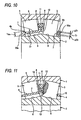
- Fig. 11 shows an example of a self-aligning roller bearing which is one kind of such roller bearings.
- This self-aligning roller bearing is constructed such that a plurality of barrel rollers 3, 3 are roliably arranged between an outer ring 1 and an inner ring 2 which are assembled concentrically in a neutral state, and a measure is provided for preventing the separation of the barrel rollers 3, 3 by retainers 4, 4 formed by subjecting a metal plate to press working.
- An outer ring race 5 which is a spherical concave surface having a single center is formed on an inner peripheral surface of the outer ring 1 of these members.
- a pair of inner ring races 6, 6, which respectively oppose the outer ring race 5, are formed on an outer peripheral surface of the inner ring 2.
- the plurality of barrel rollers 3, 3 are each formed in a symmetrical shape in which a maximum diameter portion thereof is located in an axially central portion of each of these barrel rollers 3, 3, and the plurality of barrel rollers 3, 3 are rollably arranged in two rows between the outer ring race 5 and the pair of inner ring races 6, 6.
- each of the retainers 4, 4 has a conical tube-shaped main portion 7, and an outwardly oriented flange-like large diameter-side collar portion 8 which is bent diametrically outwardly from a large diameter-side edge portion of this main portion 7.
- a plurality of pockets 10, 10 are formed in the main portion 7 intermittently concerning the circumferential direction, and each of the barrel rollers 3, 3 is rotatably retained in each of these pockets 10, 10.
- the main portion 7 is located on the diametrical inner side of the pitch circle (a circle connecting central axes of these barrel rollers 3, 3) of the plurality of barrel rollers 3, 3, with the result that the barrel rollers 3, 3 are prevented from coming out to the diametrically inner side of the main portion 7 through the pockets 10, 10.
- outer peripheral edges of the large diameter-side collar portions 8, 8 of the pair of retainers 4, 4 are respectively guided by being brought into sliding contact with an inner peripheral surface of a guide ring 11.
- This guide ring 11 is rotatably provided between the barrel rollers 3, 3 which are provided in two rows concerning the axial direction.
- a circular or an annular recessed portion 12 is formed in at least that portion of each of both end faces of each of the plurality of barrel rollers 3, 3 which opposes the large diameter-side collar portion 8.
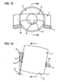
- tongues 13 are each formed at a circumferentially intermediate position of each of the pockets 10, 10 at an inner peripheral edge of the large diameter-side collar portion 8. These tongues 13 are formed in a state in which they project from the inner peripheral edge of the large diameter-side collar portion 8 toward the diametrically inner side and are bent from the large diameter-side collar portion 8 toward the one end face of the barrel roller 3 on each pocket 10 side.
- each tongue 13 is engaged with the recessed portion 12 formed in the end face of this barrel roller 3 by means of a retaining allowance ⁇ shown in Fig. 13 when the barrel roller 3 is built on the inner side of the pocket 10, thereby preventing the barrel roller 3 from coming off from inside the pocket 10 toward the radially outer side of the retainer 4.
- the barrel roller 3 which is rotatably retained in this pocket 10 is prevented from coming off from inside the pocket 10 in either an inward or outward direction concerning the diametrical direction even before the barrel roller 3 is built in between the inner peripheral surface of the outer ring and the outer peripheral surface of the inner ring 2.
- the outer ring 1 is fitted in and fixed to this housing, and the inner ring 2 is fitted over and fixed to the rotating shaft.
- the plurality of barrel rollers 3, 3 roll to allow this rotation.
- the inner ring 2 undergoes alignment inside the outer ring 1, thereby compensating for this misalignment. Since the outer ring race 5 is formed into a single spherical shape, the rolling of the plurality of barrel rollers 3, 3 is effected smoothly after the compensation of the misalignment.
- a bottomed, truncated cone-shaped second intermediate material 14 is formed by subjecting this first intermediate material to drawing, as shown in Fig. 16A .
- a bottom portion 15 of this second intermediate material 14, excluding the radially outer portion is punched by the press, thereby forming a third intermediate material 16 as is shown in Fig. 16B .
- a plurality of through holes 18 are formed in a conical tube-shaped portion 17 of this third intermediate material 16 intermittently concerning the circumferential direction, thereby forming a fourth intermediate material 19 as is shown in Fig. 16C . It should be noted that, at this juncture, while the rotation and the stopping of the third intermediate material 16 are being alternately effected, the through holes 18 are formed one at a time in the conical tube-shaped portion 17 during the stopping.
- the third intermediate material 16 is intermittently rotated by gripping portions of the bottom portion 15 by chucks, thereby consecutively replacing that portion of the conical tube-shaped portion 17 which is positioned at a working section for forming these through holes 18.
- tongue elements 20 are each formed at a widthwise central portion of one end (an upper end in Fig. 16C ) of each of these through holes 18.
- a fifth intermediate material 22 as is shown in Fig. 16D .
- the distal end portion 21 is further bent radially outwardly by a predetermined amount (until the aforementioned angle of inclination becomes 90 degrees plus) by the press to form an outwardly oriented flange-like, large diameter-side collar portion element 23, thereby forming a sixth intermediate material 24 as is shown in Fig. 16E .
- an abutment surface which is one side surface (upper surface in Fig. 16F ) of the large diameter-side collar portion 8 is adjusted into a desired shape by such as surface pressing by the press, thereby forming an eighth intermediate material 26 as is shown in Fig. 16G .
- peripheral edge portions of the pockets 10, 10 ( Figs. 11 to 15 ) are adjusted to a desired shape and size by such as surface pressing by the press, thereby forming a ninth intermediate material 27 as is shown in Fig. 16H .
- the tongue elements 20 are bent by a predetermined amount in a direction in which the distal end portions of the tongue elements 20 project from the other side surface (lower surface in Fig.
- the retainer 4 having the large diameter-side collar portion 8 such as the one shown in Figs. 11 to 15 is fabricated in the steps shown in Figs. 16A , an increase in the manufacturing cost is unavoidable. Namely, in the case of the conventional manufacturing method shown in Figs. 16A to 16I , after the radially outer end portion of the annular first intermediate material (not shown) is plastically deformed into the shape of a conical tube, as shown in Figs. 16A to 16C , the large diameter-side collar portion 8 is formed by being plastically deformed again into the annular shape, as shown in Figs. 16D and 16E . For this reason, the working efficiency is poor, and the working time becomes long, so that the manufacturing cost increases.
- the plurality of through holes 18 are formed to form the pockets 10, 10, as shown in Figs . 16B and 16C , the operation of forming these through holes 18 must be performed while intermittently rotating the third intermediate material 16 or the fourth intermediate material 19 by predetermined degrees. For this reason, not only does the working time become long, a precise indexing operation is required, so that the cost increases. Although it is possible to perform the operation of forming the plurality of through holes 18 simultaneously so as to shorten the working time, a complex and large-scale working apparatus is required, so that this also constitutes a factor for higher cost.
- the method of manufacturing a retainer for a roller bearing in accordance with the invention has been invented to improve the efficiency of the manufacturing operation and realize the low cost of the retainer.
- a retainer for a roller bearing which is made of a metal plate and has a tubular main portion, a plurality of pockets formed in the main portion intermittently concerning a circumferential direction and capable of retaining rollers rollably on respective inner sides thereof, and an outwardly oriented flange-like collar portion formed at an axial end of the main portion.
- This manufacturing method comprises the steps of: forming an annular intermediate material by subjecting the metal plate to die cutting; forming a second intermediate material by forming a plurality of through holes in the intermediate material intermittently concerning the circumferential direction; plastically deforming a portion of the second intermediate material excluding a radially outer end portion thereof into a tubular shape; and forming the portion plastically deformed into the tubular shape as the main portion, forming a portion corresponding to the radially outer end portion of the second intermediate material as the collar portion or a collar portion element for forming the collar portion, and forming portions corresponding to the through holes as the pockets.
- the die cutting of the intermediate material and the operation of forming the through holes may be performed one after another, or may be per formed simultaneously if the capacity of a press machine is sufficient.
- the radially outer end portion of the annular second intermediate material is utilized as the annular collar portion without being temporarily formed into a tubular shape. For this reason, the operation of forming this collar portion can be performed efficiently.
- a method of manufacturing a retainer for a roller bearing comprising the steps of: forming an annular intermediate material by subjecting the metal plate to die cutting; forming a second intermediate material by forming a plurality of through holes in the intermediate material intermittently concerning the circumferential direction; plastically deforming a portion of the second intermediate material excluding a radially outer endportion thereof into a tubular shape; cutting off the radially outer end portion; and forming the portion plastically deformed into the tubular shape as the main portion, and forming portions corresponding to the through holes as the pockets.
- the plurality of through holes can be worked simultaneously without requiring an especially complex and large-scale working apparatus.
- the method of manufacturing a retainer for a roller bearing in accordance with the invention comprises the step in which portions which are each present between a central hole of the second intermediate material and each of the through holes are each formed in an arch shape in which a respective intermediate portion projects in a radial direction of the second intermediate material relative to both endportions, and the step in which the arch-like portion is extended when the portion of the second intermediate material excluding the radially outer end portion thereof is plastically deformed into the tubular shape.
- a portion of an outer peripheral edge of the intermediate material is left as connected to a portion of the metal plate when the annular intermediate material is formed by subjecting the metal plate to die cutting, and after the second intermediate material is formed by forming the plurality of through holes at least in the intermediate material, a portion of an outer peripheral edge of the second intermediate material is cut off from the portion of the metal plate.
- the positioning of this intermediate material in the circumferential direction and the radial direction can be easily accomplished during the formation of these through holes.
- the intermediate materials are consecutively fed (are moved intermittently by predetermined lengths) on a manufacturing line with the plurality of intermediate materials connected to the metal plate, the operation of forming the through holes in the respective intermediate materials can be performed efficiently.
- the method of manufacturing a retainer for a roller bearing in accordance with the invention comprises the step in which after the formation of the main portion and the plurality of pockets, those portions of the main portion corresponding to portions which are each present between a central hole of the second intermediate material and each of the through holes are subjected to plastic working, to thereby render the plate thickness of the portion subjected to the plastic working greater than the plate thickness of a remaining portion of the main portion.
- a retainer for a roller bearing which is made of a metal plate, comprising: a tubular main portion; a plurality of pockets formed in the main portion intermittently concerning a circumferential direction and capable of retaining rollers rollably on respective inner sides thereof; and an outwardly oriented flange-like collar portion formed at an axial end of the main portion, wherein an annular intermediate material is formed by subjecting the metal plate to die cutting, and after a second intermediate material is formed by forming a plurality of through holes in the intermediate material intermittently concerning the circumferential direction, a portion of the second intermediate material excluding a radially outer end portion thereof is plastically deformed into a tubular shape, whereby the portion plastically deformed into the tubular shape is formed as the main portion, a portion corresponding to the radially outer end portion of the second intermediate material is formed as the collar portion or a collar portion element for forming the collar portion, and portions corresponding to the through holes are formed as the pockets.
- a retainer for a roller bearing which is made of a metal plate, comprising: a tubular main portion; and a plurality of pockets formed in the main portion intermittently concerning a circumferential direction and capable of retaining rollers rollably on respective inner sides thereof, wherein an annular intermediate material is formed by subjecting the metal plate to die cutting, and after a second intermediate material is formed by forming a plurality of through holes in the intermediate material intermittently concerning the circumferential direction, a portion of the second intermediate material excluding a radially outer end portion thereof is plastically deformed into a tubular shape, the radially outer end portion being subsequently cut off, whereby the portion plastically deformed into the tubular shape is formed as the main portion, and portions corresponding to the through holes are formed as the pockets.
- reference numeral 1 denotes an outer ring; 2, an inner ring; 3, a barrel roller; 4, 4a, 4b, retainers; 5, an outer ring race; 6, an inner ring race; 7, a main portion; 8, 8a, a large diameter-side collar portion; 10, 10a, pockets; 11, a guide ring; 12, a recessed portion; 13, a tongue; 14, a second intermediate material; 15, abottomportion; 16, athirdintermediatematerial; 17, aconical tube-shaped portion; 18, 18a, 18b, through holes; 19, a fourth intermediate material; 20, a tongue element; 21, a distal end portion; 22, a fifth intermediate material; 23, a large diameter-sidecollarportion; 24, a sixth intermediate material; 25, a seventh intermediate material; 26, an eighth intermediate material; 27, a ninth intermediate material; 28, 28a, first intermediate materials; 29, 29a, second intermediate materials; 30, 30a, belt-shaped portions; 31, 31a, third intermediate materials; 32, a receiving block; 33, a
- FIGs. 1 to 4 show a first embodiment of the invention.
- a main characteristic of this embodiment is a method of manufacturing a retainer 4 which is used by being incorporated into a self-aligning roller bearing.
- a description will be given centering on a characteristic portion of the first embodiment.
- annular first intermediate material 28 such as the one shown in Fig. 2A and corresponding to an intermediate material described in the claims, is first formed by subjecting a metal plate serving as a basic material to die cutting by means of a press.
- the shape of an inner peripheral edge of this first intermediate material 28 is a corrugated shape concerning a circumferential direction.
- through holes 18a, 18a are respectively formed at those portions of the first intermediate material 28 in each of which a phase concerning the circumferential direction agrees with a radially inwardly projecting portion of the inner peripheral edge of this first intermediate material 28, thereby forming a second intermediate material 29 as is shown in Fig. 2B .
- the operation of forming the through holes 18a, 18a is performed by die cutting by means of a press, and all the through holes 18a, 18a are die cut simultaneously. It should be noted that if the capacity of a press machine is sufficiently large, the metal plate can be die cut at a stroke into the second intermediate material 29.
- these through holes 18a, 18a respectively have shapes in which their widthwise dimension concerning the circumferential direction becomes smaller toward the radially inner side, and their radially inner end portion is made to enter the inner side of a radially inwardly projecting portion of the inner peripheral edge of the second intermediate material 29.
- belt-shaped portions 30, 30 which are each present between a central hole of the second intermediate material 29 and each of the through holes 18a, 18a are each formed in an arch shape in which a respective intermediate portion projects radially inwardly of both end portions.
- the projecting direction of this arch shape may be made opposite to the illustrated example.
- tongue elements 20, 20 are respectively formed at central portions of radially outer edges of the through holes 18a, 18a.
- a radially inner portion (a portion located radially inwardly of a chain line ⁇ in Fig. 2B ) of the second intermediate material 29 is plastically deformed into the shape of a conical tube, to thereby obtain a third intermediate material 31 as is shown in Fig. 2C .
- a third intermediate material 31 as shown from Fig. 3A to Fig. 3B ( Fig. 4 ) in a state in which a radially outer portion (a portion located radially outwardly of the chain line a in Fig.
- portion subjected to plastic deformation into the shape of a conical tube in the above-described manner is set as a main portion 7, and a portion corresponding to the radially outer end portion of the second intermediate material 29 is set as a large diameter-side collar portion 9. Further, portions corresponding to the respective through holes 18a, 18a are respective set as pockets 10, 10 (not shown in Fig. 2C ; see Fig. 1 ).
- the structure of the third intermediate material 31 shown in Fig. 2C referred to above is similar to the structure shown in Fig. 16F referred to earlier. Accordingly, in the case of this embodiment, the third intermediate material 31 is subsequently subjected to working similar to that of Figs. 16G to 16I referred to earlier, thereby completing the retainer 4.
- the radially outer end portion of the annular second intermediate material 29 is utilized as the annular large diameter-side collar portion 8 without taking the trouble of temporarily forming it into a tubular shape. For this reason, the operation of forming this large diameter-side collar portion 8 can be performed efficiently.
- the plurality of through holes 18a, 18a can be worked simultaneously without requiring an especially complex working apparatus.
- the radially inner portion of the second intermediate material 29 is plastically deformed into the shape of a conical tube, it is possible to prevent a reduction of the cross-sectional area of each of these belt-shaped portions 30, 30 which are each present between the central hole of the second intermediate
- the retainer 4 of high quality can be fabricated at low cost.
- Fig. 5 shows a second embodiment of the invention.
- outside dimensions of first and second intermediate materials 28a and 29a shown in Figs. 5A and 5B are made slightly larger than in the case of the first embodiment. Consequently, the widthwise dimension concerning the radial direction of that portion of the second intermediate material 29a which is clamped by the receiving block 32 and the pressing block 33 making up the press machine shown in Figs. 3 and 4 (the portion located radially outwardly of a chain line ⁇ ' in Fig. 5B ) is sufficiently secured.
- Fig. 3A to Fig. 3B Fig.
- a radially outer end portion of this large diameter-side collar portion preform 35 is cut off by trimming the large diameter-side collar portion preform 35 so as to form the large diameter-side collar portion 8, thereby forming a fourth intermediate material 36 (the same as the third intermediate material 31 of the first embodiment shown in Fig. 2C referred to above) as is shown in Fig. 5D .
- the construction and operation of the other portions, including a subsequent working method, are the same as in the case of the above-described first embodiment.
- Fig. 6 shows a third embodiment of the invention.
- the annular first intermediate materials 28 are formed in a widthwise (vertically in Fig. 6 ) intermediate portion of this metal plate 37 by performing die cutting by means of a press.
- two diametrically opposite portions of the outer edge of the first intermediate material 28 are kept as connected respectively to portions of the metal plate 37.
- the first intermediate materials 28 are respectively formed at positions of equal intervals in the longitudinal direction of the metal plate 28 while the metal plate 28 is being fed in the longitudinal direction (in the left-and-right direction in Fig. 6 ) of this metal plate 28 in the same procedure.
- the respective first intermediate materials 28 together with the metal plate 37 are consecutively fed on the manufacturing line in the longitudinal direction of the metal plate 37.
- the plurality of through holes 18a, 18a are consecutively formed in these first intermediate materials 28, thereby working these first intermediate materials 28 into the second intermediate materials 29, as shown in Fig. 6B .
- these second intermediate materials 29 together with the metal plate 37 are similarly fed consecutively on the manufacturing line in the longitudinal direction of the metal plate 37.
- radially inner portions of these second intermediate materials 29 are consecutively plastically deformed into the shape of a conical tube, thereby respectively working these second intermediate materials 29 into the third intermediate materials 31, as shown in Fig. 6C .
- the second intermediate materials 29 are subsequently subjected to working similar to that of Figs. 16G to 16I referred to above, thereby completing the retainers 4 ( Fig. 1 ).
- the operation of cutting off the intermediate material or the retainer 4 from the metal plate 37 is performed in some stage after the formation of the third intermediate material 31 (e.g., immediately after the formation of this third intermediate material 31 or completion of the retainer 4).
- the working with respect to the first and second intermediate materials 28 and 29 is carried out in a state in which these first and second intermediate materials 28 and 29 are left as connected to the metal plate 37, the positioning of these first and second intermediate materials 28 and 29 in the circumferential direction and the radial direction can be easily accomplished.
- the plurality of intermediate materials can be integrally handled through the metal plate 37. For this reason, in the case of this embodiment, the working with respect to apluralityof intermediate materials can be performed efficiently, and the working time can be shorted, making it possible to attain a further reduction of the manufacturing cost.
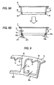
- FIG. 7 shows a fourth embodiment of the invention.
- a retainer 4a which serves as an object of the manufacturing method of the embodiment, is one shown in Fig. 17 referred to earlier, i.e., one which does not have a collar portion on either end of the main portion 7.
- a third intermediate material 31b having a large diameter-side collar portion 8a is formed in the same working procedure as that in the case of the first embodiment shown in Fig. 2 referred to above, i.e., in the order of Figs. 7A, 7B, and 7C .
- the shape of each of pockets 10a, 10a ( Fig.
- this large diameter-side collar portion 8a is then removed by means of a press, thereby forming a fourth intermediate material 38, as is shown in Fig. 8D. Subsequently, inner peripheral edges of the pockets 10a, 10a formed in the main portion 7 making up this fourth intermediate material 38 are subjected to surface pressing or the like so as to adjust the shape and dimensions of these pockets 10a, 10a, thereby completing the retainer 4a.
- Figs. 8 to 10 show a fifth embodiment of the invention.
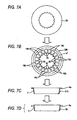
- the metal plate is first subjected to predetermined working in the same way as in the cases of the first embodiment shown in Fig. 2 referred to above, the second embodiment shown in Fig. 5 , and the third embodiment shown in Fig. 6 , so as to fabricate an intermediate material having the conical tube-shaped main portion 7, the plurality of pockets 10, 10, and the large diameter-side collar portion 8.
- the belt-shaped portions 30, 30 provided at the small diameter-side end portion of the main portion 7 are respectively plastically deformed by being compressed in the direction of the generating line (or in the axial direction) of this main portion 7.
- the dimension ⁇ T1 of the belt-shaped portion 30a denotes an amount of increase in the cross-sectional height toward the radially outer side of the retainer 4b and the dimension T2 similarly denotes an amount of increase in the cross-sectional height toward the radially inner side thereof as a result of the fact that the belt-shaped portion 30 before compression is plastically deformed.
- inner surfaces of the belt-shaped portions 30a, 30a formed in the above-described manner are respectively formed as single flat surfaces.
- the plate thickness T30a of the respective belt-shaped portions 30a, 30a is made greater than the plate thickness T7 of the remaining portions of the main portion 7 (T30a > T7). For this reason, the rigidity of these belt-shaped portions 30a, 30a can be sufficiently ensured without increasing the dimensions of the belt-shaped portions 30a, 30a concerning the direction of the generating line (or the axial direction) . In addition, areas of the inner surfaces of these belt-shaped portions 30a, 30a can be enlarged.
- the end faces of the plurality of rollers 3, 3 during use can be guided with wide areas by the inner surfaces of these belt-shaped portions 30a, 30a, thereby making it possible to stabilize the attitude of these rollers 3, 3. Furthermore, when, at the time of assembling the roller bearing, the inner surfaces of the belt-shaped portions 30a, 30a are used as guiding surfaces when inserting the rollers 3, 3 into the respective pockets 10, 10, the inserting operation of these rollers 3, 3, can be easily effected.
- these pockets 10, 10a may be formed to a desired shape and size simultaneously with the formation of these pockets 10, 10a by subjecting the peripheral edge portions of the through holes 18a, 18b before the formation of the pockets 10, 10a to the surface pressing in advance.
- the surface pressing can be simultaneously provided more easily to the plurality of peripheral edge portions in the case of providing it to the peripheral edge portions of the through holes 18a, 18b formed in the annular second intermediate materials 29, 29a, 29b than in the case of providing it to the peripheral edge portions of the pockets 10, 10a formed in the conical tube-shaped main portion 7. Accordingly, the adoption of the method of providing the surface pressing to the peripheral edge portions of the through holes 18a, 18b in the above-described manner shortens the working time and facilitates the reduction in the manufacturing cost.
- the method of manufacturing a retainer for a roller bearing in accordance with the invention can be implemented regardless of the kind of roller bearing (self-aligning roller bearing, cylindrical roller bearing, tapered roller bearing, etc.) into which the retainer for a roller bearing is incorporated, insofar as the retainer for a roller bearing has a tubular main portion (in the case of the invention according to claim 1, plus an outwardly oriented flange-like collar portion which is bent radially outwardly from an axial end of this main portion).
- the present invention is applicable to a method of manufacturing a retainer for a roller bearing for rollably retaining a plurality of rollers in a roller bearing which is applied to a rotatively supporting portion for making up various machine equipment and which uses rollers as rolling elements.
Landscapes
- Engineering & Computer Science (AREA)
- General Engineering & Computer Science (AREA)
- Mechanical Engineering (AREA)
- Rolling Contact Bearings (AREA)
Claims (4)
- Procédé de fabrication d'une cage (4) pour un roulement à rouleaux qui est faite d'une plaque métallique et a une partie principale tubulaire (7), une pluralité de poches (10) formées dans la partie principale (7) à intervalles dans une direction circonférentielle et pouvant retenir des rouleaux à rotation sur des côtés intérieurs respectifs de celles-ci, et une partie de collier formant rebord orientée vers l'extérieur (8) formée en une extrémité axiale de la partie principale (7), comprenant les étapes consistant à :former un matériau intermédiaire annulaire (28) en soumettant la plaque métallique à un découpage à l'emporte-pièce ;former un second matériau intermédiaire (29) en formant une pluralité de trous de passages (18a) servant de poches (10) dans le matériau intermédiaire (28) à intervalles dans la direction circonférentielle ;déformer plastiquement une partie (7) du second matériau intermédiaire (29) à l'exclusion d'une partie d'extrémité extérieure (8) de celui-ci en une partie principale (8) ayant une forme tubulaire ;dans lequel ladite partie d'extrémité radialement extérieure du second matériau intermédiaire (29) est la partie de collier (8) ou un élément de partie de collier pour former la partie de collier (8),caractérisé en ce que des parties (30) qui sont chacune présentes entre un trou central du second matériau intermédiaire (29) et chacun des trous de passage (18a) sont chacune formées en une forme d'arc dans lequel une partie intermédiaire respective fait saillie dans une direction radiale du second matériau intermédiaire (29) par rapport aux deux parties d'extrémité, etla partie en forme d'arc est allongée quand la partie du second matériau intermédiaire (29) à l'exclusion de la partie d'extrémité radialement extérieure de celui-ci est déformée plastiquement en la forme tubulaire.
- Procédé de fabrication d'une cage (4) pour un roulement à rouleaux selon la revendication 1, comprenant les étapes consistant à :découper la partie d'extrémité radialement extérieure.
- Procédé de fabrication d'une cage pour un roulement à rouleaux selon la revendication 1 ou 2, dans lequel une partie d'un bord périphérique extérieur du matériau intermédiaire est laissée reliée à une partie de la plaque métallique quand le matériau intermédiaire annulaire (28) est formé en soumettant la plaque métallique à un découpage à l'emporte-pièce, et
après que le second matériau intermédiaire (29) a été formé en formant la pluralité de trous de passage (18a) au moins dans le matériau intermédiaire, une partie d'un bord périphérique extérieure du second matériau intermédiaire (29) est découpé de la partie de la plaque métallique. - Procédé de fabrication d'une cage pour un roulement à rouleaux selon la revendication 1 ou 2, dans lequel après la formation de la partie principale (7) et de la pluralité de poches (10), ces parties de la partie principale (7) correspondant à ces parties qui sont chacune présentes entre un trou central du second matériau intermédiaire (29) et chacun des trous de passage (18a) sont soumises à un travail plastique, pour ainsi rendre l'épaisseur de plaque de la partie soumise au travail plastique supérieure à l'épaisseur de plaque d'une partie restante de la partie principale (7).
Applications Claiming Priority (3)
| Application Number | Priority Date | Filing Date | Title |
|---|---|---|---|
| JP2003290455 | 2003-08-08 | ||
| JP2004210946A JP4517759B2 (ja) | 2003-08-08 | 2004-07-20 | ころ軸受用保持器の製造方法 |
| PCT/JP2004/011635 WO2005015038A1 (fr) | 2003-08-08 | 2004-08-06 | Procede de fabrication d'une cage de roulement a rouleaux, et cage de roulement a rouleaux |
Publications (3)
| Publication Number | Publication Date |
|---|---|
| EP1653098A1 EP1653098A1 (fr) | 2006-05-03 |
| EP1653098A4 EP1653098A4 (fr) | 2006-10-25 |
| EP1653098B1 true EP1653098B1 (fr) | 2010-06-23 |
Family
ID=34137940
Family Applications (1)
| Application Number | Title | Priority Date | Filing Date |
|---|---|---|---|
| EP04771610A Expired - Lifetime EP1653098B1 (fr) | 2003-08-08 | 2004-08-06 | Procede de fabrication d'une cage de roulement a rouleaux, et cage de roulement a rouleaux |
Country Status (5)
| Country | Link |
|---|---|
| US (1) | US7571543B2 (fr) |
| EP (1) | EP1653098B1 (fr) |
| JP (1) | JP4517759B2 (fr) |
| DE (1) | DE602004027815D1 (fr) |
| WO (1) | WO2005015038A1 (fr) |
Families Citing this family (16)
| Publication number | Priority date | Publication date | Assignee | Title |
|---|---|---|---|---|
| JP4561501B2 (ja) * | 2005-06-30 | 2010-10-13 | 日本精工株式会社 | ころ軸受用保持器の製造方法 |
| JP2007016816A (ja) * | 2005-07-05 | 2007-01-25 | Nsk Ltd | ころ軸受用保持器及びその製造方法 |
| CN101253341B (zh) * | 2005-09-01 | 2012-10-17 | Ntn株式会社 | 滚柱轴承 |
| JP2007303536A (ja) * | 2006-05-10 | 2007-11-22 | Nsk Ltd | 円錐ころ軸受用保持器の製造方法 |
| DE202008014280U1 (de) * | 2008-10-27 | 2010-04-08 | Ab Skf | Wälzlagerkäfig |
| EP2710274B1 (fr) * | 2011-05-17 | 2017-03-15 | Aktiebolaget SKF | Cage destinée à un roulement à rouleaux toroïdal |
| US20140363116A1 (en) | 2011-12-21 | 2014-12-11 | Nakanishi Metal Works Co., Ltd. | Roller bearing cage and manufacturing method thereof |
| EP2823909A4 (fr) | 2012-03-07 | 2016-11-09 | Nakanishi Metal Works Co | Cage de roulement à rouleaux et procédé de fabrication de cette dernière ainsi que procédé de fabrication d'un roulement à rouleaux |
| TWI473672B (zh) * | 2012-05-25 | 2015-02-21 | Needle Roller Bearing Co Ltd | Roller holder processing method |
| US9033587B1 (en) | 2013-01-29 | 2015-05-19 | Roller Bearing Company Of America, Inc. | Cage for a roller bearing and a method of manufacturing the same |
| CN103691836B (zh) * | 2013-12-27 | 2016-03-09 | 大连瑞谷科技有限公司 | 剖分轴承保持架端面锁点冲压胎 |
| USD809033S1 (en) * | 2015-12-28 | 2018-01-30 | Ntn Corporation | Retainer for rolling bearing |
| KR101921643B1 (ko) | 2016-06-24 | 2018-11-26 | (주)엠에스텍 | 롤러베어링의 리테이너 제조방법 |
| DE102017221475A1 (de) * | 2016-12-13 | 2018-06-14 | Aktiebolaget Skf | Lagerkäfig, Wälzlager und Verfahren |
| DE102017221473A1 (de) * | 2016-12-13 | 2018-06-14 | Aktiebolaget Skf | Lagerkäfig, Wälzlager und Verfahren |
| JP7469639B2 (ja) * | 2020-05-18 | 2024-04-17 | 中西金属工業株式会社 | 自動調心ころ軸受用保持器の製造方法 |
Family Cites Families (11)
| Publication number | Priority date | Publication date | Assignee | Title |
|---|---|---|---|---|
| US1602350A (en) * | 1923-01-19 | 1926-10-05 | Skf Svenska Kullagerfab Ab | Ball retainer for ball bearings and method of making the same |
| US3240543A (en) * | 1964-07-01 | 1966-03-15 | Torrington Co | Thrust bearing |
| DE2146056C3 (de) * | 1971-09-15 | 1983-11-24 | INA Wälzlager Schaeffler KG, 8522 Herzogenaurach | Verfahren zur Herstellung eines Axial-Wälzlagerkäfigs für zylindrische Wälzkörper |
| JPS5442551A (en) * | 1977-09-12 | 1979-04-04 | Fujikoshi Kk | Method of producing cage for conical roll bearing |
| JPH01158820U (fr) * | 1988-04-25 | 1989-11-02 | ||
| DE4140161A1 (de) * | 1991-12-05 | 1993-06-09 | Walter Pottiez Gmbh, 7519 Sulzfeld, De | Verfahren und werkzeug zum herstellen von stanzteilen fuer kugellagerkaefige |
| JP3039087B2 (ja) * | 1991-12-05 | 2000-05-08 | 日本精工株式会社 | 保持器付自動調心ころ軸受 |
| JP4239240B2 (ja) * | 1998-06-15 | 2009-03-18 | 日本精工株式会社 | ころ軸受用保持器の製造方法 |
| JP2000104737A (ja) * | 1998-09-30 | 2000-04-11 | Nsk Ltd | 円すいころ軸受用プレス型保持器の製造方法 |
| JP2001038440A (ja) * | 1999-07-26 | 2001-02-13 | Nsk Ltd | 円すいころ軸受保持器の製造方法 |
| JP2001153143A (ja) * | 1999-11-29 | 2001-06-08 | Nsk Ltd | 円筒ころ軸受 |
-
2004
- 2004-07-20 JP JP2004210946A patent/JP4517759B2/ja not_active Expired - Lifetime
- 2004-08-06 EP EP04771610A patent/EP1653098B1/fr not_active Expired - Lifetime
- 2004-08-06 WO PCT/JP2004/011635 patent/WO2005015038A1/fr not_active Ceased
- 2004-08-06 US US10/567,568 patent/US7571543B2/en not_active Expired - Fee Related
- 2004-08-06 DE DE602004027815T patent/DE602004027815D1/de not_active Expired - Lifetime
Also Published As
| Publication number | Publication date |
|---|---|
| EP1653098A1 (fr) | 2006-05-03 |
| US7571543B2 (en) | 2009-08-11 |
| US20060204158A1 (en) | 2006-09-14 |
| WO2005015038A1 (fr) | 2005-02-17 |
| DE602004027815D1 (de) | 2010-08-05 |
| JP4517759B2 (ja) | 2010-08-04 |
| JP2005090740A (ja) | 2005-04-07 |
| EP1653098A4 (fr) | 2006-10-25 |
Similar Documents
| Publication | Publication Date | Title |
|---|---|---|
| EP1653098B1 (fr) | Procede de fabrication d'une cage de roulement a rouleaux, et cage de roulement a rouleaux | |
| US8424209B2 (en) | Assembling method of bearing unit | |
| JP5466100B2 (ja) | 円すいころ軸受 | |
| JP4337189B2 (ja) | 円錐ころ軸受の組立方法 | |
| JP4328076B2 (ja) | スラスト軸受及びその製造方法 | |
| EP2963308A1 (fr) | Élément de retenue pour palier à aiguille radial et procédé de fabrication de ce dernier | |
| US9151328B2 (en) | Conical roller bearing | |
| JP2000257638A (ja) | ころ軸受用保持器及びその製造方法 | |
| JP2001038440A (ja) | 円すいころ軸受保持器の製造方法 | |
| JP2005273755A (ja) | スラスト円筒ころ軸受用保持器とその製造方法 | |
| KR20200029496A (ko) | 구름 베어링 및 보유 지지기 | |
| JPH11101240A (ja) | 円すいころ軸受用保持器およびその製造方法 | |
| JP2000104737A (ja) | 円すいころ軸受用プレス型保持器の製造方法 | |
| JP2005195143A (ja) | 針状ころ軸受 | |
| JP2002295482A (ja) | 円錐ころ軸受 | |
| JP4561501B2 (ja) | ころ軸受用保持器の製造方法 | |
| JP2005076727A (ja) | 止め輪組付方法及び止め輪組付構体 | |
| JP2008232171A (ja) | ころ軸受 | |
| EP2860414B1 (fr) | Roulement à rouleaux coniques | |
| CN1833114A (zh) | 滚子轴承保持架的制造方法和滚子轴承保持架 | |
| JP2007016816A (ja) | ころ軸受用保持器及びその製造方法 | |
| JP4269962B2 (ja) | ラジアルニードル軸受用保持器の製造方法 | |
| US20010045015A1 (en) | Assembly technique for double row ball or roller bearings | |
| JP2002147450A (ja) | 球面ころ軸受用保持器 | |
| JP2015045371A (ja) | 波形保持器の製造方法及び波形保持器 |
Legal Events
| Date | Code | Title | Description |
|---|---|---|---|
| PUAI | Public reference made under article 153(3) epc to a published international application that has entered the european phase |
Free format text: ORIGINAL CODE: 0009012 |
|
| 17P | Request for examination filed |
Effective date: 20060208 |
|
| AK | Designated contracting states |
Kind code of ref document: A1 Designated state(s): DE |
|
| A4 | Supplementary search report drawn up and despatched |
Effective date: 20060921 |
|
| RIC1 | Information provided on ipc code assigned before grant |
Ipc: B21D 53/12 20060101ALI20060915BHEP Ipc: F16C 33/46 20060101AFI20050224BHEP |
|
| DAX | Request for extension of the european patent (deleted) | ||
| RBV | Designated contracting states (corrected) |
Designated state(s): DE |
|
| 17Q | First examination report despatched |
Effective date: 20070727 |
|
| GRAP | Despatch of communication of intention to grant a patent |
Free format text: ORIGINAL CODE: EPIDOSNIGR1 |
|
| GRAS | Grant fee paid |
Free format text: ORIGINAL CODE: EPIDOSNIGR3 |
|
| GRAA | (expected) grant |
Free format text: ORIGINAL CODE: 0009210 |
|
| AK | Designated contracting states |
Kind code of ref document: B1 Designated state(s): DE |
|
| REF | Corresponds to: |
Ref document number: 602004027815 Country of ref document: DE Date of ref document: 20100805 Kind code of ref document: P |
|
| PLBE | No opposition filed within time limit |
Free format text: ORIGINAL CODE: 0009261 |
|
| STAA | Information on the status of an ep patent application or granted ep patent |
Free format text: STATUS: NO OPPOSITION FILED WITHIN TIME LIMIT |
|
| 26N | No opposition filed |
Effective date: 20110324 |
|
| REG | Reference to a national code |
Ref country code: DE Ref legal event code: R097 Ref document number: 602004027815 Country of ref document: DE Effective date: 20110323 |
|
| PGFP | Annual fee paid to national office [announced via postgrant information from national office to epo] |
Ref country code: DE Payment date: 20190723 Year of fee payment: 16 |
|
| REG | Reference to a national code |
Ref country code: DE Ref legal event code: R119 Ref document number: 602004027815 Country of ref document: DE |
|
| PG25 | Lapsed in a contracting state [announced via postgrant information from national office to epo] |
Ref country code: DE Free format text: LAPSE BECAUSE OF NON-PAYMENT OF DUE FEES Effective date: 20210302 |