EP1653430A2 - Dispositif de support pour signaux routiers variables - Google Patents
Dispositif de support pour signaux routiers variables Download PDFInfo
- Publication number
- EP1653430A2 EP1653430A2 EP05015123A EP05015123A EP1653430A2 EP 1653430 A2 EP1653430 A2 EP 1653430A2 EP 05015123 A EP05015123 A EP 05015123A EP 05015123 A EP05015123 A EP 05015123A EP 1653430 A2 EP1653430 A2 EP 1653430A2
- Authority
- EP
- European Patent Office
- Prior art keywords
- support frame
- carrying device
- bolt
- roller
- bracket
- Prior art date
- Legal status (The legal status is an assumption and is not a legal conclusion. Google has not performed a legal analysis and makes no representation as to the accuracy of the status listed.)
- Granted
Links
Images


Classifications
-
- G—PHYSICS
- G09—EDUCATION; CRYPTOGRAPHY; DISPLAY; ADVERTISING; SEALS
- G09F—DISPLAYING; ADVERTISING; SIGNS; LABELS OR NAME-PLATES; SEALS
- G09F11/00—Indicating arrangements for variable information in which the complete information is permanently attached to a movable support which brings it to the display position
- G09F11/30—Indicating arrangements for variable information in which the complete information is permanently attached to a movable support which brings it to the display position the display elements being fed one by one from storage place to a display position
-
- E—FIXED CONSTRUCTIONS
- E01—CONSTRUCTION OF ROADS, RAILWAYS, OR BRIDGES
- E01F—ADDITIONAL WORK, SUCH AS EQUIPPING ROADS OR THE CONSTRUCTION OF PLATFORMS, HELICOPTER LANDING STAGES, SIGNS, SNOW FENCES, OR THE LIKE
- E01F9/00—Arrangement of road signs or traffic signals; Arrangements for enforcing caution
- E01F9/60—Upright bodies, e.g. marker posts or bollards; Supports for road signs
- E01F9/604—Upright bodies, e.g. marker posts or bollards; Supports for road signs specially adapted for particular signalling purposes, e.g. for indicating curves, road works or pedestrian crossings
- E01F9/608—Upright bodies, e.g. marker posts or bollards; Supports for road signs specially adapted for particular signalling purposes, e.g. for indicating curves, road works or pedestrian crossings for guiding, warning or controlling traffic, e.g. delineator posts or milestones
- E01F9/61—Special features of delineator posts, e.g. with parts cantilevered toward the roadway or fixed vertically on a tilted surface
-
- G—PHYSICS
- G09—EDUCATION; CRYPTOGRAPHY; DISPLAY; ADVERTISING; SEALS
- G09F—DISPLAYING; ADVERTISING; SIGNS; LABELS OR NAME-PLATES; SEALS
- G09F11/00—Indicating arrangements for variable information in which the complete information is permanently attached to a movable support which brings it to the display position
Definitions
- the present invention relates to a carrying device, in particular for variable message signs, by means of which relatively heavy mechanical and electronic units can be fastened in particular to ceilings.
- Such support devices are known since the introduction of mechanical or electro-optical variable message traffic signs and traffic control systems at the latest. Usually, such support devices are arranged vertically on associated masts or bridge pillars or laterally on tunnel walls, so that the road users can recognize the signal transmitter located in the support device already from far away.
- an optical display device which provides significant dimensional size advantages by aligning the carriage substantially parallel to a given observer's direction of motion and comprising the display panel of a plurality of spaced-apart characters in the order corresponding to the character to be displayed Moving direction is arranged behind one another arranged display segments, wherein the display segments are arranged substantially parallel to the surface normal of the display panel receiving support device or inclined at less than 45 ° relative to the surface normal.
- the support frame has hitherto mostly been firmly mounted on the tunnel ceiling, which brings considerable problems with initial installation, with necessary repairs and with the replacement of individual display segments.
- the present invention is therefore an object of the invention to provide a support device, in particular for variable message signs, which can be easily installed in any spatial arrangement, in the repairs of the signal generator or their replacement by a single fitter can be made without tools in a simple manner.
- a support device in particular for variable message signs, which has a first flat support frame, which is preferably fastened to a ceiling of a tunnel extending parallel thereto, further comprising a second flat support frame, which is suitable for receiving signal transmitters, wherein the second support frame at a first end of the support device via first connecting means is pivotally connected to the first support frame and at a second end via second connecting means releasably lockable to the first support frame.
- first connecting means comprise two hooks which are arranged on the second support frame, and two bolt-shaped portions which are arranged on the first support frame, wherein the hooks can engage around the bolt-shaped portions pivotally.
- the second connecting means at least one, preferably two bracket on the second support frame, and at least one movable latching device on the first Support frame for fixing the bracket.
- the bracket in the region of its upper end on a bolt which is insertable into at least one slot formed in the first support frame, wherein a first pivotable locking device for fixing the strap prevents the bolt after its introduction into the slot on the exit.
- the first latching device is designed as a spring-assisted locking hook which has a substantially V-shaped recess into which the bolt can be inserted simultaneously during its movement into the slot, the web of the V-shaped recess serving as a support surface suitable for the bolt.
- the bracket preferably has at its upper end a head having a tapered front end into which a first and a second edge of the head open. Due to this configuration, it is easily possible to provide an easy-to-use second locking device which cooperates with the two edges.
- a leaf spring is disposed between the roller and a cross rail of the first support frame, which presses the roller down, whereby the roller is pressed into its locking position and unlocking of the second support frame due to vibrations is prevented.
- the second edge preferably extends in the western direction at 45 ° to the vertical.
- the anchoring and guiding of the roller on the first support frame is preferably carried out in that the roller is integrated at its ends via two bolts, which are guided in two substantially at 45 ° to the vertical extending slots in the first support frame.
- the support device 1 is composed of a first support frame 3 and a second support frame 5.
- the first support frame 3 can be fastened permanently to its base by means of conventional fastening means, the invention being particularly suitable for ceilings of tunnels, etc., although the use of the support device 1 according to the invention is also conceivable in any other arbitrary spatial arrangement.
- the first support frame 3 usually has two at a certain distance from each other arranged angle rails 7, which are connected by corresponding cross rails.
- the resulting outer frame can be supplemented by a rear wall 11, although this is not required.
- the angle rails 7 and the cross rails 9 together form a receiving space, in which the second support frame 5 can be inserted.
- the second support frame 5 is similar in shape to the first support frame 3, being suitable for receiving rotary mechanical or electro-optical signalers 13 or similar units.
- the signalers 13 shown are lamellar arranged sections of a variable traffic sign, the are either designed as mechanically movable prism-shaped elements or are equipped with a plurality of luminous points, so that they represent an optical luminous sign in the entirety.
- the first and the second support frame 3, 5 are pivotally connected in the illustrated suspended state of the second support frame 5 via first connecting means 15.
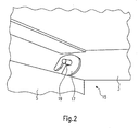
- Fig. 2 shows a section of the support device 1 with the first connecting means 15.
- the connecting means 15 are therefore composed of two arranged on the longitudinal sides of the second support frame 5 hooks 17 and two bolt-shaped portions 19, which are arranged on the first support frame 3 together.
- the hooks 17 are shaped so that they engage around the bolt-shaped portions 19 so deep that the connection remains in the direction of the opening of the hook 17 even with slight pivoting movements. Pivoting movements carried out in the direction of the closed side of the hook 17 are possible beyond the horizontal without loss of connection occurring. Due to this connection, the two support frames 3, 5 both easily connected to each other and also be released from each other and provide a pivotal connection, the overall but still ensures a very safe handling of the support device 1 at hanging down the second support frame 5.
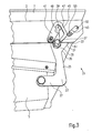
- FIG. 3 the opposite end of the support device 1 is shown in a section, wherein second connecting means 21 for locking the second support frame 5 on the first support frame 3 are shown in detail.
- the second connecting means 21 initially have at least one bracket 23 attached to the second support frame 5, which can also be designed as a swivel bracket.
- the bracket 23 has an essentially angled shape, wherein the longer leg 25 extends upward and the shorter leg 27 extends substantially horizontally and is rotatably or fixedly secured to the second support frame 5 at its end.
- the longer leg 25 has at its end a head 29 which has a tapered front end 31 into which a first, upper edge 33 and a second, lower edge 35 open.
- the lower edge 35 is substantially straight and approximately 45 ° oblique to the vertical, while the upper edge 33 may have a rounded shape.
- an outwardly projecting pin 37 is also arranged.
- This bolt 37 extends during insertion of the second support frame 5 in the first Support frame 3 in a slot 39 which is formed in a vertical angle leg of the first support frame 3 and extends substantially perpendicular thereto.
- a first latching device 41 and a second latching device 43 are arranged on the first support frame 3.
- Each of the two devices 41, 43 taken alone would be sufficient for a releasable locking of the second support frame 5 on the first support frame 3, however, resulting from the combined connection of the two mechanisms additional advantages in the operation and safety aspects.
- the first latching device 41 is designed as a spring-supported pawl 45, which has a substantially V-shaped and tilted by 90 ° recess 47.
- the pin 37 is simultaneously inserted into the recess 47, and the pawl 45 makes a lateral compensating movement in accordance with the tilted V-shape of the recess 47.
- the spring-assisted pawl 45 swings back to its original position and the bolt 37 through the web 49 of the V-shaped recess 47 on a further downward movement is prevented.
- the web 49 preferably has a horizontal edge, so that the bolt 37 can rest on it safely.
- a second latching device 43 may be provided extending in the transverse direction of the first support frame 3 movable roller 51, which is integrated at its outer ends via two bolts 53 which are guided in two slots 55 in the first support frame 3.
- the elongated holes 55 extend at about 45 ° to the vertical, so that an obliquely guided upward and downward movement of the roller 51 is made possible.
- the pin 37 of the bracket 23 is guided in the slot 39, and thus also makes the head 29 of the bracket 23 a defined upward movement.
- the upper edge 33 of the head 29 comes into contact with the roller 51 and pushes it along the slots 55 laterally obliquely upward until the front tip end 31 of the head 29 is above the height of the longitudinal axis of the roller 51.
- the roller 51 slides back into the slots 55 obliquely down to the initial state, and when the fitter releases the second support frame 5, the sloping lower edge 35 of the head 29 from above on the roller 51 from and is through this at a downward movement prevented.
- the double locking device 41, 43 thus serves in addition to greater safety also for easy and safe lifting of the locking connection between the second support frame 5 and the first support frame 3.
- a leaf spring (not shown) between the roller 51 and the corresponding cross rail 9 of the first support frame 3 may be arranged, which presses the roller 51 down.
Landscapes
- Engineering & Computer Science (AREA)
- Physics & Mathematics (AREA)
- General Physics & Mathematics (AREA)
- Theoretical Computer Science (AREA)
- Architecture (AREA)
- Civil Engineering (AREA)
- Structural Engineering (AREA)
- Road Signs Or Road Markings (AREA)
- Mirrors, Picture Frames, Photograph Stands, And Related Fastening Devices (AREA)
- Measurement Of Velocity Or Position Using Acoustic Or Ultrasonic Waves (AREA)
Applications Claiming Priority (1)
| Application Number | Priority Date | Filing Date | Title |
|---|---|---|---|
| DE202004016565U DE202004016565U1 (de) | 2004-10-26 | 2004-10-26 | Tragvorrichtung für Signalgeber |
Publications (3)
| Publication Number | Publication Date |
|---|---|
| EP1653430A2 true EP1653430A2 (fr) | 2006-05-03 |
| EP1653430A3 EP1653430A3 (fr) | 2007-09-12 |
| EP1653430B1 EP1653430B1 (fr) | 2012-06-06 |
Family
ID=35735087
Family Applications (1)
| Application Number | Title | Priority Date | Filing Date |
|---|---|---|---|
| EP05015123A Expired - Lifetime EP1653430B1 (fr) | 2004-10-26 | 2005-07-12 | Dispositif de support pour signaux routiers variables |
Country Status (4)
| Country | Link |
|---|---|
| US (1) | US20060086880A1 (fr) |
| EP (1) | EP1653430B1 (fr) |
| BR (1) | BRPI0504347A (fr) |
| DE (1) | DE202004016565U1 (fr) |
Cited By (2)
| Publication number | Priority date | Publication date | Assignee | Title |
|---|---|---|---|---|
| EP2058786A1 (fr) | 2007-11-12 | 2009-05-13 | Dambach-Werke GmbH | Dispositif d'affichage lumineux pour la représentation de signaux dans des tunnels ou autres |
| DE102010024817A1 (de) | 2010-06-23 | 2011-12-29 | Siemens Aktiengesellschaft | Vorrichtung zur wechselnden Darstellung von Verkehrszeichen |
Families Citing this family (1)
| Publication number | Priority date | Publication date | Assignee | Title |
|---|---|---|---|---|
| EP3667650B1 (fr) * | 2018-12-12 | 2023-06-07 | DMS - Displays & Mobility Solutions, Lda | Panneau électronique de signalisation routière, processus d'application et ses utilisations |
Citations (1)
| Publication number | Priority date | Publication date | Assignee | Title |
|---|---|---|---|---|
| EP0917703B1 (fr) | 1996-08-07 | 2000-04-26 | Dambach-Werke GmbH | Dispositif d'affichage optique |
Family Cites Families (9)
| Publication number | Priority date | Publication date | Assignee | Title |
|---|---|---|---|---|
| US3844591A (en) * | 1973-09-24 | 1974-10-29 | White Welding & Mfg Inc | Door latch means |
| FR2482179A1 (fr) * | 1980-05-08 | 1981-11-13 | Renault | Dispositif de verrouillage d'une vitre pivotante |
| FR2656636B1 (fr) * | 1989-12-29 | 1992-05-22 | Laporte Sa | Dispositif a chevalet pliant de securite pour un panneau de signalisation ou analogue. |
| FR2730254B1 (fr) * | 1995-02-03 | 1997-04-25 | Securite Signalisation | Support mobile de panneau de signalisation |
| US6347819B1 (en) * | 1999-09-15 | 2002-02-19 | Shawn Plaxco | Safety latching mechanism |
| GB0000039D0 (en) * | 2000-01-05 | 2000-02-23 | Tremblay Martin | Pivoting and locking device for hinged windows |
| DE10104122C2 (de) * | 2000-12-11 | 2002-10-24 | Dambach Werke Gmbh | Gehäuse mit einer Tür oder Klappe |
| US20040144045A1 (en) * | 2003-01-23 | 2004-07-29 | Granger Timothy L | Interior mounted cover having a breathable membrane for a roof ventilator |
| US7140649B1 (en) * | 2004-09-30 | 2006-11-28 | Tuffy Security Products | Rotary latch and lock mechanism |
-
2004
- 2004-10-26 DE DE202004016565U patent/DE202004016565U1/de not_active Expired - Lifetime
-
2005
- 2005-07-12 EP EP05015123A patent/EP1653430B1/fr not_active Expired - Lifetime
- 2005-09-20 BR BRPI0504347-6A patent/BRPI0504347A/pt not_active IP Right Cessation
- 2005-09-28 US US11/236,900 patent/US20060086880A1/en not_active Abandoned
Patent Citations (1)
| Publication number | Priority date | Publication date | Assignee | Title |
|---|---|---|---|---|
| EP0917703B1 (fr) | 1996-08-07 | 2000-04-26 | Dambach-Werke GmbH | Dispositif d'affichage optique |
Cited By (3)
| Publication number | Priority date | Publication date | Assignee | Title |
|---|---|---|---|---|
| EP2058786A1 (fr) | 2007-11-12 | 2009-05-13 | Dambach-Werke GmbH | Dispositif d'affichage lumineux pour la représentation de signaux dans des tunnels ou autres |
| DE102010024817A1 (de) | 2010-06-23 | 2011-12-29 | Siemens Aktiengesellschaft | Vorrichtung zur wechselnden Darstellung von Verkehrszeichen |
| DE102010024817B4 (de) * | 2010-06-23 | 2012-06-06 | Siemens Aktiengesellschaft | Vorrichtung zur wechselnden Darstellung von Verkehrszeichen |
Also Published As
| Publication number | Publication date |
|---|---|
| EP1653430A3 (fr) | 2007-09-12 |
| EP1653430B1 (fr) | 2012-06-06 |
| DE202004016565U1 (de) | 2006-03-09 |
| US20060086880A1 (en) | 2006-04-27 |
| BRPI0504347A (pt) | 2006-06-27 |
Similar Documents
| Publication | Publication Date | Title |
|---|---|---|
| DE102012213104A1 (de) | Containerverriegelung | |
| EP4560092A2 (fr) | Montant de garde-corps pour balustrade avant d'échafaudage, échafaudage avec garde-corps frontal et procédé de conversion d'une balustrade frontale au niveau d'un échafaudage | |
| EP3491205A1 (fr) | Élément de fixation | |
| DE202023105830U1 (de) | Vorrichtung zur Anbringung von Absturzsicherungen an Baugerüsten | |
| DE202024100688U1 (de) | Vorrichtung zur Anbringung von Absturzsicherungen an Baugerüsten | |
| AT13583U1 (de) | Halterungsteil für ein Geländer | |
| EP1607364B1 (fr) | Systeme de contrepoids d'une grue | |
| EP3712354B1 (fr) | Plateforme de coffrage | |
| EP4433673B1 (fr) | Coffrage de panneau avec un dispositif de raccordement et procédé | |
| EP1653430B1 (fr) | Dispositif de support pour signaux routiers variables | |
| DE19651901C2 (de) | Sicherheitsschutzgeländerelement, insbesondere für in verschiedenen Richtungen verlaufende Gerüstbauten | |
| DE102010052492B4 (de) | Vorrichtung zur Aufnahme eines Rohres | |
| EP2058786B1 (fr) | Dispositif d'affichage lumineux pour la représentation de signaux dans des tunnels ou autres | |
| DE29621995U1 (de) | Absperrvorrichtung mit einem Zaun | |
| EP3656918B1 (fr) | Dispositif de barrière de rail pour installation mobile de sécurisation de voies | |
| DE102022214178A1 (de) | Kletterschuh, Höheneinstellvorrichtung, System und Verfahren | |
| DE19734333C2 (de) | Schiebeleiter | |
| DE112006001213T5 (de) | Temporäre Fixierungsstruktur für eine Informationsvorrichtung | |
| WO2021110888A1 (fr) | Coffrage | |
| DE202013003385U1 (de) | Vorrichtung zur Aufnahme eines Geländerpfostens | |
| CH696403A5 (de) | Verankerungsbüchse für die Verankerung einer Konsole in einer Betonwand und eine Konsole. | |
| DE202024001499U1 (de) | Vorrichtung zur Anbringung von Absturzsicherungen an Baugerüsten | |
| DE1784065A1 (de) | Verschalungsvorrichtung zur Herstellung von zu den Aussenwaenden senkrechten oder parallelen Mauern gleichzeitig mit den entsprechenden Decken | |
| DE202024001500U1 (de) | Vorrichtung zur Anbringung von Absturzsicherungen an Baugerüsten | |
| AT500579B1 (de) | Verankerungsbüchse für die verankerung einer konsole in einer betonwand, ein verankerungsmittel, ein halte- und verschlussdeckel und eine konsole |
Legal Events
| Date | Code | Title | Description |
|---|---|---|---|
| PUAI | Public reference made under article 153(3) epc to a published international application that has entered the european phase |
Free format text: ORIGINAL CODE: 0009012 |
|
| AK | Designated contracting states |
Kind code of ref document: A2 Designated state(s): AT BE BG CH CY CZ DE DK EE ES FI FR GB GR HU IE IS IT LI LT LU LV MC NL PL PT RO SE SI SK TR |
|
| AX | Request for extension of the european patent |
Extension state: AL BA HR MK YU |
|
| PUAL | Search report despatched |
Free format text: ORIGINAL CODE: 0009013 |
|
| AK | Designated contracting states |
Kind code of ref document: A3 Designated state(s): AT BE BG CH CY CZ DE DK EE ES FI FR GB GR HU IE IS IT LI LT LU LV MC NL PL PT RO SE SI SK TR |
|
| AX | Request for extension of the european patent |
Extension state: AL BA HR MK YU |
|
| 17P | Request for examination filed |
Effective date: 20080305 |
|
| 17Q | First examination report despatched |
Effective date: 20080418 |
|
| AKX | Designation fees paid |
Designated state(s): AT CH DE LI |
|
| RAP1 | Party data changed (applicant data changed or rights of an application transferred) |
Owner name: SWARCO FUTURIT VERKEHRSSYSTEME GES.M.B.H. |
|
| GRAP | Despatch of communication of intention to grant a patent |
Free format text: ORIGINAL CODE: EPIDOSNIGR1 |
|
| GRAS | Grant fee paid |
Free format text: ORIGINAL CODE: EPIDOSNIGR3 |
|
| GRAA | (expected) grant |
Free format text: ORIGINAL CODE: 0009210 |
|
| AK | Designated contracting states |
Kind code of ref document: B1 Designated state(s): AT CH DE LI |
|
| REG | Reference to a national code |
Ref country code: CH Ref legal event code: EP Ref country code: AT Ref legal event code: REF Ref document number: 561351 Country of ref document: AT Kind code of ref document: T Effective date: 20120615 |
|
| REG | Reference to a national code |
Ref country code: DE Ref legal event code: R096 Ref document number: 502005012775 Country of ref document: DE Effective date: 20120802 |
|
| REG | Reference to a national code |
Ref country code: CH Ref legal event code: NV Representative=s name: HEPP WENGER RYFFEL AG, CH |
|
| PLBE | No opposition filed within time limit |
Free format text: ORIGINAL CODE: 0009261 |
|
| STAA | Information on the status of an ep patent application or granted ep patent |
Free format text: STATUS: NO OPPOSITION FILED WITHIN TIME LIMIT |
|
| 26N | No opposition filed |
Effective date: 20130307 |
|
| REG | Reference to a national code |
Ref country code: DE Ref legal event code: R097 Ref document number: 502005012775 Country of ref document: DE Effective date: 20130307 |
|
| PGFP | Annual fee paid to national office [announced via postgrant information from national office to epo] |
Ref country code: CH Payment date: 20140930 Year of fee payment: 10 |
|
| PGFP | Annual fee paid to national office [announced via postgrant information from national office to epo] |
Ref country code: AT Payment date: 20140731 Year of fee payment: 10 |
|
| PGFP | Annual fee paid to national office [announced via postgrant information from national office to epo] |
Ref country code: DE Payment date: 20140929 Year of fee payment: 10 |
|
| REG | Reference to a national code |
Ref country code: DE Ref legal event code: R119 Ref document number: 502005012775 Country of ref document: DE |
|
| REG | Reference to a national code |
Ref country code: CH Ref legal event code: PL |
|
| REG | Reference to a national code |
Ref country code: AT Ref legal event code: MM01 Ref document number: 561351 Country of ref document: AT Kind code of ref document: T Effective date: 20150712 |
|
| PG25 | Lapsed in a contracting state [announced via postgrant information from national office to epo] |
Ref country code: CH Free format text: LAPSE BECAUSE OF NON-PAYMENT OF DUE FEES Effective date: 20150731 Ref country code: DE Free format text: LAPSE BECAUSE OF NON-PAYMENT OF DUE FEES Effective date: 20160202 Ref country code: LI Free format text: LAPSE BECAUSE OF NON-PAYMENT OF DUE FEES Effective date: 20150731 |
|
| PG25 | Lapsed in a contracting state [announced via postgrant information from national office to epo] |
Ref country code: AT Free format text: LAPSE BECAUSE OF NON-PAYMENT OF DUE FEES Effective date: 20150712 |