EP1653727A1 - Empecher le vacillement d'image dans un image vidéo numérisé - Google Patents
Empecher le vacillement d'image dans un image vidéo numérisé Download PDFInfo
- Publication number
- EP1653727A1 EP1653727A1 EP04292558A EP04292558A EP1653727A1 EP 1653727 A1 EP1653727 A1 EP 1653727A1 EP 04292558 A EP04292558 A EP 04292558A EP 04292558 A EP04292558 A EP 04292558A EP 1653727 A1 EP1653727 A1 EP 1653727A1
- Authority
- EP
- European Patent Office
- Prior art keywords
- video signal
- signal
- type
- digitized
- analog input
- Prior art date
- Legal status (The legal status is an assumption and is not a legal conclusion. Google has not performed a legal analysis and makes no representation as to the accuracy of the status listed.)
- Withdrawn
Links
- 238000000034 method Methods 0.000 claims abstract description 20
- 230000006835 compression Effects 0.000 description 2
- 238000007906 compression Methods 0.000 description 2
- 230000002950 deficient Effects 0.000 description 2
- 238000006243 chemical reaction Methods 0.000 description 1
- 230000003111 delayed effect Effects 0.000 description 1
- 238000011156 evaluation Methods 0.000 description 1
- 230000007274 generation of a signal involved in cell-cell signaling Effects 0.000 description 1
- 230000007704 transition Effects 0.000 description 1
Images

Classifications
-
- H—ELECTRICITY
- H04—ELECTRIC COMMUNICATION TECHNIQUE
- H04N—PICTORIAL COMMUNICATION, e.g. TELEVISION
- H04N5/00—Details of television systems
- H04N5/76—Television signal recording
- H04N5/78—Television signal recording using magnetic recording
- H04N5/782—Television signal recording using magnetic recording on tape
- H04N5/783—Adaptations for reproducing at a rate different from the recording rate
-
- H—ELECTRICITY
- H04—ELECTRIC COMMUNICATION TECHNIQUE
- H04N—PICTORIAL COMMUNICATION, e.g. TELEVISION
- H04N5/00—Details of television systems
- H04N5/76—Television signal recording
- H04N5/91—Television signal processing therefor
- H04N5/93—Regeneration of the television signal or of selected parts thereof
- H04N5/95—Time-base error compensation
Definitions
- the present invention relates to a method for generating a digital video signal from an analog input video signal, and to an apparatus having means for digitizing an analog input video signal using such method.
- Digital storage devices such as a HDD-recorder or a DVD-recorder usually have an analog video input and an analog video output. Internally, however, the video signal is digitized for processing such as MPEG compression etc.
- An incoming analog video signal is first digitized by means of an 8, 9 or even 10-bit ADC (Analog-to-Digital converter), hereafter referred to as video converter, before any digital processing or compression is performed.
- the digitized video signal normally conforms to the ITU R-656 standard.
- the processed video signal may be stored on a recording medium such as for example a DVD disc, a VCD disc, or a DVHS tape. It may also be viewed directly after MPEG decoding. For this purpose the digitized video signal is converted back into an analog video signal by means of a DAC (Digital-to-Analog converter).
- DAC Digital-to-Analog converter
- Analog-to-digital conversion is performed using ICs that work well if there is an analog input video signal that is in conformity with a standard (ITU-R BT624 for PAL, SMPTE 170M for NTSC, etc.).
- a standard ITU-R BT624 for PAL, SMPTE 170M for NTSC, etc.
- the analog input video signal is not in complete conformity with a standard, e.g. when it comes from a VCR in trick mode (like pause or fast forward). In these cases e.g. the fields (upper field, lower field) are mixed up.
- the ADC IC still generates a digital video signal, this signal contains errors.
- the encoded and decoded video signal displayed on the TV is normal. This means the interlaced field sequence is correctly displayed and there is no jitter of the picture.
- the analog input video signal does not conform strictly to the video standards, then the digitized video signal becomes defective, giving rise to imperfections such as a jittering picture when the 1st field and the 2nd field are displayed in the wrong sequence.
- this object is achieved by a method for generating a digital video signal from an analog input video signal including the steps of:
- the signal Before digitizing the analog input video signal it is determined whether the signal comes from a non-standard type of source, e.g. a VCR. If the signal is received from a TV broadcaster or from a DVD then there are no errors to be expected. It is then checked for the existence of an error state, i.e. if the non-standard signal source is in a state where errors are likely to occur.
- a non-standard type of source e.g. a VCR.
- possible error states are the trick modes such as Pause or Fast Forward/Rewind. If such an error state exists, an error prone part of the digitized video signal is replaced with a substitute signal part.
- a predefined placeholder is inserted in the digitized video signal.
- This predefined placeholder is defined such that it is correct in most, or even all, cases.
- an internal signal of the video converter having a stable timing is used for replacing the field bit.
- the whole field is shifted by a determined number of lines.
- the determined number of lines should be adjustable by the user or automatically.
- the digitized video signal is kept unchanged.
- a "safe" analog input video signal i.e. a presumably error free signal, there is no need to perform any replacement, as such replacement could generate unexpected errors.
- the above steps are preferably repeated constantly.
- the invention has the advantage that even in case of a slightly distorted analog input video input signal as e.g. from a VCR in trick mode the resulting digital video signal has no errors.
- the invention is not limited to a VCR as signal source. It is likewise applicable to other types of sources using a tape as recording medium, e.g. camcorders, or any other device delivering a non-standard analog video signal.
- a method according to the invention is used in an apparatus for receiving and/or recording a digital video signal, having an input for receiving an analog video signal and means for digitizing a received analog video signal
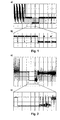
- Fig. 1a a normal CVBS analog video signal at the instant of vertical timing (V timing) with correct pre-equalization pulses, serration pulses and post-equalization pulses is shown. An enlarged portion of this signal is depicted in Fig. 1b).
- FIG. 2a A distorted analog video signal is depicted in Fig. 2a).
- Fig. 2b shows an enlarged portion of this signal.
- the signal comes from a VCR operated in trick mode, e.g. in Pause or Fast Forward/Rewind mode.
- Such a signal usually is defective and shows a plurality of distortions such as a non-standard line length or a non-standard vertical synchronization signal.
- the V timing of the output CVBS signal becomes non-standard.
- the video converter cannot generate the proper Field signals from the H (horizontal) and V timing and the resulting digital video signal becomes jittery.
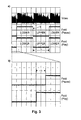
- a jittery digital video signal is depicted in Fig. 3a).
- Fig. 3b shows an enlarged portion of this signal.
- the Field signal (Lower or Upper, also referred to as Even or Odd) in trick mode (pause), and the field signal in normal mode.
- the duration T of the low level period of the field signal is the same during trick mode as during normal mode.
- the duration of the high level period of the field signal changes by a delay ⁇ during trick mode.
- the start position of the lower field is shifted by about 180 ⁇ s, which corresponds to a delay of three lines. Consequently, the lower field of the picture on the TV screen will be displayed three lines later than normal, too.
- the falling edge of the field signal is used as a trigger tr.
- a first step 1 the type of the signal source is detected.
- changes to the video signal are only performed in an A/V input mode.
- one possibility is to analyze the time-base of the video signal. As the VCR signal has a non-stable time-base, and signals coming from a TV broadcaster or a DVD player have a stable time-base, this feature can be used to detect the signal source. If the input signal has a non-stable time-base, it is deemed to be received from a VCR.
- the analog input video signal is received from a VCR
- a second step 2 it is analyzed whether the VCR is in an error state, i.e. in a state such as trick mode that is likely to produce errors.
- the Vsync is inserted by the main signal processor in trick mode. Normally, the frequency of this inserted Vsync is non-standard. This means that if the frequency of Vsync is determined to be out of a specified range, then the VCR is in trick mode.
- step 3 the analog input video signal is digitized. If the analog input video signal is not received from a VCR, or if it is received from a VCR operating in normal mode, then after digitization 3 the digitized video signal is kept unchanged, as there is no need to perform any correction. In fact, an unnecessary correction might rather generate an undesired error. If, however, the input signal comes from a VCR operating in trick mode, then after digitization 3 in a further step 4 an error prone part of the digitized signal is replaced with a substitute signal part.
- bit6 of the SAV/EAV header indicates the field: BIT 7 BIT 6 (F) BIT 5 (V) BIT 4 (H) BIT 3 (P3) BIT 2 (P2) BIT 1 (P1) BIT 0 (P0) 1 field bit vertical blanking bit format reserved; evaluation not recommended (protection bits according to ITU 656)
- Many video converters provide an internal signal (e.g. Vgate) that has a stable timing. This signal is used for replacing the field bit in the SAV/EAV header. This replacement is done by changing the register settings of the video converter.
- a final step 5 the digitized video signal is submitted to further processing like MPEG coding etc.
- the above steps are preferably constantly repeated.
- Vgate internal signal
- the value of the internal signal (Vgate) usually is programmable. It can, therefore, be programmed to be stable. For example, the signal may be delayed by one line. The starting point for the signal is the transition from upper to lower. For the above example of a delay of about 180 ⁇ s a shift backwards by three lines is performed.
- a device using this method for preventing picture jitter is user adjustable. Then the user may adjust the delay to different numbers of lines, for example three, four or five lines, until the jitter disappears. Even if only a single source of the analog input video signal is used different delay values are advantageous, e.g. when the source uses a tape that was recorded on another device. In such a case larger delay values may be needed to reduce jitter.
Landscapes
- Engineering & Computer Science (AREA)
- Multimedia (AREA)
- Signal Processing (AREA)
- Television Signal Processing For Recording (AREA)
- Signal Processing For Digital Recording And Reproducing (AREA)
Priority Applications (8)
| Application Number | Priority Date | Filing Date | Title |
|---|---|---|---|
| EP04292558A EP1653727A1 (fr) | 2004-10-28 | 2004-10-28 | Empecher le vacillement d'image dans un image vidéo numérisé |
| EP05105414A EP1617659A3 (fr) | 2004-07-16 | 2005-06-20 | Empêcher le scintillement d'image dans un signal vidéo numérisée |
| TW094122223A TWI371970B (en) | 2004-07-16 | 2005-07-01 | Preventing picture jitter in a digitized video signal |
| US11/180,252 US7495708B2 (en) | 2004-07-16 | 2005-07-13 | Preventing picture jitter in a digitized video signal |
| KR1020050063177A KR101105828B1 (ko) | 2004-07-16 | 2005-07-13 | 디지털 비디오 신호에서 화상 지터 방지 방법 및 장치 |
| CN2005100846459A CN1722814B (zh) | 2004-07-16 | 2005-07-15 | 防止数字化视频信号中的图像抖动的方法和装置 |
| JP2005207081A JP2006054862A (ja) | 2004-07-16 | 2005-07-15 | デジタル化されたビデオ信号における画像ジッタの防止 |
| MYPI20053264A MY141108A (en) | 2004-07-16 | 2005-07-15 | Preventing picture jitter in a digitized video signal |
Applications Claiming Priority (1)
| Application Number | Priority Date | Filing Date | Title |
|---|---|---|---|
| EP04292558A EP1653727A1 (fr) | 2004-10-28 | 2004-10-28 | Empecher le vacillement d'image dans un image vidéo numérisé |
Publications (1)
| Publication Number | Publication Date |
|---|---|
| EP1653727A1 true EP1653727A1 (fr) | 2006-05-03 |
Family
ID=34931487
Family Applications (1)
| Application Number | Title | Priority Date | Filing Date |
|---|---|---|---|
| EP04292558A Withdrawn EP1653727A1 (fr) | 2004-07-16 | 2004-10-28 | Empecher le vacillement d'image dans un image vidéo numérisé |
Country Status (1)
| Country | Link |
|---|---|
| EP (1) | EP1653727A1 (fr) |
Cited By (1)
| Publication number | Priority date | Publication date | Assignee | Title |
|---|---|---|---|---|
| GB2438689A (en) * | 2005-12-05 | 2007-12-05 | Hitachi Ltd | Method of detecting correction methods for feature images |
Citations (3)
| Publication number | Priority date | Publication date | Assignee | Title |
|---|---|---|---|---|
| US5241398A (en) * | 1990-06-26 | 1993-08-31 | Sony Corporation | Dropout compensation during track jumps |
| EP0592932A2 (fr) * | 1992-10-14 | 1994-04-20 | NOKIA TECHNOLOGY GmbH | Procédé d'atténuation du bruit d'un signal vidéo, et réducteur de bruit |
| EP0705034A2 (fr) * | 1994-09-28 | 1996-04-03 | Matsushita Electric Industrial Co., Ltd. | Appareil de traitement numérique |
-
2004
- 2004-10-28 EP EP04292558A patent/EP1653727A1/fr not_active Withdrawn
Patent Citations (3)
| Publication number | Priority date | Publication date | Assignee | Title |
|---|---|---|---|---|
| US5241398A (en) * | 1990-06-26 | 1993-08-31 | Sony Corporation | Dropout compensation during track jumps |
| EP0592932A2 (fr) * | 1992-10-14 | 1994-04-20 | NOKIA TECHNOLOGY GmbH | Procédé d'atténuation du bruit d'un signal vidéo, et réducteur de bruit |
| EP0705034A2 (fr) * | 1994-09-28 | 1996-04-03 | Matsushita Electric Industrial Co., Ltd. | Appareil de traitement numérique |
Cited By (3)
| Publication number | Priority date | Publication date | Assignee | Title |
|---|---|---|---|---|
| GB2438689A (en) * | 2005-12-05 | 2007-12-05 | Hitachi Ltd | Method of detecting correction methods for feature images |
| GB2438689B (en) * | 2005-12-05 | 2009-04-01 | Hitachi Ltd | Method of detecting feature images |
| US7853084B2 (en) | 2005-12-05 | 2010-12-14 | Hitachi, Ltd. | Method of detecting feature images |
Similar Documents
| Publication | Publication Date | Title |
|---|---|---|
| EP0574892B1 (fr) | Dispositif pour l'enregistrement et la reproduction d'un signal vidéo numérique | |
| KR100814662B1 (ko) | 아날로그 영상 인터페이스를 통한 권리 전달 방법 및 장치 | |
| US7099388B2 (en) | System and method for enabling compatibility between digital and analog television systems | |
| CN101796812A (zh) | 唇形同步系统和方法 | |
| KR100411699B1 (ko) | 복제방지신호발생기를갖는ntsc인코더 | |
| US8035746B2 (en) | Time base correction for digitized video signal | |
| US7495708B2 (en) | Preventing picture jitter in a digitized video signal | |
| EP1617659A2 (fr) | Empêcher le scintillement d'image dans un signal vidéo numérisée | |
| US20090278983A1 (en) | Digital video signal transmitter and receiver and including system | |
| EP0151468A1 (fr) | Système de mémorisation de signal | |
| US6844943B2 (en) | Method and apparatus for video recording from previous recorded video | |
| EP1681879A1 (fr) | Correction d'erreurs de base de temps pour signaux numériques vidéo | |
| JP4510621B2 (ja) | ビデオ装置 | |
| JP2002010206A (ja) | 映像信号出力装置及び映像信号出力方法 | |
| JP2004343516A (ja) | 記録再生処理装置 | |
| US10375442B2 (en) | Copy protection system | |
| JPH10290455A (ja) | 映像信号処理装置 | |
| JPH07298221A (ja) | 映像信号の伝送における同期信号のエラー検出方法および装置 | |
| JPH09238304A (ja) | コピーガード発生装置 | |
| JPH10285560A (ja) | 映像信号処理装置 | |
| JP2001313907A (ja) | ビデオ信号処理装置 | |
| JPH09238305A (ja) | コピーガード発生装置 |
Legal Events
| Date | Code | Title | Description |
|---|---|---|---|
| PUAI | Public reference made under article 153(3) epc to a published international application that has entered the european phase |
Free format text: ORIGINAL CODE: 0009012 |
|
| AK | Designated contracting states |
Kind code of ref document: A1 Designated state(s): AT BE BG CH CY CZ DE DK EE ES FI FR GB GR HU IE IT LI LU MC NL PL PT RO SE SI SK TR |
|
| AX | Request for extension of the european patent |
Extension state: AL HR LT LV MK |
|
| AKX | Designation fees paid | ||
| STAA | Information on the status of an ep patent application or granted ep patent |
Free format text: STATUS: THE APPLICATION IS DEEMED TO BE WITHDRAWN |
|
| 18D | Application deemed to be withdrawn |
Effective date: 20061104 |
|
| REG | Reference to a national code |
Ref country code: DE Ref legal event code: 8566 |