EP1653785A1 - Dispositif d'allumage pour une lampe a decharge haute pression et une lampe a decharge haute pression avec un dispositif d'allumage et méthode d'opération. - Google Patents
Dispositif d'allumage pour une lampe a decharge haute pression et une lampe a decharge haute pression avec un dispositif d'allumage et méthode d'opération. Download PDFInfo
- Publication number
- EP1653785A1 EP1653785A1 EP05022448A EP05022448A EP1653785A1 EP 1653785 A1 EP1653785 A1 EP 1653785A1 EP 05022448 A EP05022448 A EP 05022448A EP 05022448 A EP05022448 A EP 05022448A EP 1653785 A1 EP1653785 A1 EP 1653785A1
- Authority
- EP
- European Patent Office
- Prior art keywords
- discharge lamp
- pressure discharge
- voltage
- ignition
- ignition device
- Prior art date
- Legal status (The legal status is an assumption and is not a legal conclusion. Google has not performed a legal analysis and makes no representation as to the accuracy of the status listed.)
- Granted
Links
Images

Classifications
-
- H—ELECTRICITY
- H05—ELECTRIC TECHNIQUES NOT OTHERWISE PROVIDED FOR
- H05B—ELECTRIC HEATING; ELECTRIC LIGHT SOURCES NOT OTHERWISE PROVIDED FOR; CIRCUIT ARRANGEMENTS FOR ELECTRIC LIGHT SOURCES, IN GENERAL
- H05B41/00—Circuit arrangements or apparatus for igniting or operating discharge lamps
- H05B41/14—Circuit arrangements
- H05B41/26—Circuit arrangements in which the lamp is fed by power derived from DC by means of a converter, e.g. by high-voltage DC
- H05B41/28—Circuit arrangements in which the lamp is fed by power derived from DC by means of a converter, e.g. by high-voltage DC using static converters
- H05B41/288—Circuit arrangements in which the lamp is fed by power derived from DC by means of a converter, e.g. by high-voltage DC using static converters with semiconductor devices and specially adapted for lamps without preheating electrodes, e.g. for high-intensity discharge lamps, high-pressure mercury or sodium lamps or low-pressure sodium lamps
- H05B41/2881—Load circuits; Control thereof
-
- Y—GENERAL TAGGING OF NEW TECHNOLOGICAL DEVELOPMENTS; GENERAL TAGGING OF CROSS-SECTIONAL TECHNOLOGIES SPANNING OVER SEVERAL SECTIONS OF THE IPC; TECHNICAL SUBJECTS COVERED BY FORMER USPC CROSS-REFERENCE ART COLLECTIONS [XRACs] AND DIGESTS
- Y02—TECHNOLOGIES OR APPLICATIONS FOR MITIGATION OR ADAPTATION AGAINST CLIMATE CHANGE
- Y02B—CLIMATE CHANGE MITIGATION TECHNOLOGIES RELATED TO BUILDINGS, e.g. HOUSING, HOUSE APPLIANCES OR RELATED END-USER APPLICATIONS
- Y02B20/00—Energy efficient lighting technologies, e.g. halogen lamps or gas discharge lamps
Definitions
- the invention relates to an ignition device according to the preamble of patent claim 1 and a high-pressure discharge lamp with such an ignition device and to an operating method for a high-pressure discharge lamp.
- EP-A 0 294 604 describes a circuit arrangement for operating a vehicle headlight high-pressure discharge lamp with a sinusoidal alternating voltage.
- the circuit arrangement comprises a series resonant circuit which generates a sinusoidal alternating voltage with a frequency of 45 kilohertz and an amplitude of up to 18000 volts, which ignites the lamp within a period of 6 milliseconds, for igniting the gas discharge in the high-pressure discharge lamp at the resonant capacitor by means of the resonant superelevation ,
- the ignition device according to the invention for a provided with a Zündangeselektrode high-pressure discharge lamp has a series resonant circuit for generating the ignition voltage for the high-pressure discharge lamp whose resonance inductance comprises the primary winding of a transformer, the secondary winding of this transformer is provided for applying the Zündoselektrode the high-pressure discharge lamp with the ignition voltage.
- the ignition device according to the invention has a simple structure.
- the ignition device according to the invention enables a complete electrical isolation between the ignition device and its power supply circuit or the operating circuit of the high-pressure discharge lamp.
- the resonant capacitance of the series resonant circuit is advantageously formed by at least two capacitors, which are connected in such a way that they prevent a direct current flow between the voltage supply circuit and the components of the igniter.
- a DC voltage isolating capacitor is also provided. to reduce the sodium loss in the discharge plasma due to the diffusion of sodium ions to the discharge vessel wall.
- the capacitance of the DC separation capacitor is dimensioned such that on the one hand the auxiliary ignition electrode is acted upon by a sufficiently high voltage to ignite the gas discharge and on the other hand, the aforementioned sodium diffusion is reduced to a sufficient extent. If the capacitance or too high leakage current of the DC separation capacitor is too large, no sufficient reduction of the sodium diffusion is achieved, and if the capacitance is too small, the auxiliary starting electrode can not be subjected to a sufficiently high voltage to ignite the gas discharge.
- the transformer of the ignition device according to the invention is advantageously designed as an autotransformer, that is, the transformer has only a single winding with a first winding section, which is designed as a primary winding, and a second winding section, which is designed as a secondary winding, wherein a connection of these winding sections as common connection is formed.
- a space-saving arrangement of the transformer and the ignition device can be ensured, so class the complete ignition device can be integrated into the lamp base of the high-pressure discharge lamp.
- the winding or the windings of the transformer of the ignition device according to the invention are preferably designed as directional layer winding or layer windings in chamber or cross winding in order to ensure the highest possible natural resonant frequency of the transformer.
- the operating method according to the invention for a high-pressure discharge lamp is characterized by providing a resonance-boosted AC voltage for igniting the gas discharge in the discharge vessel of the high-pressure discharge lamp, wherein the resonance-boosted AC voltage is generated by means of a transformer and transformed into a higher voltage, that of a starting auxiliary electrode of the high-pressure discharge lamp is supplied.
- the resonance-boosted AC voltage is generated by means of the primary winding of the transformer, which is formed as part of a series resonant circuit, and the auxiliary auxiliary voltage supplied to the higher voltage is generated by means of the secondary winding of the transformer.
- frequency modulation of the supply voltage generated by the voltage source is preferably carried out in order to take into account changes in the resonant frequency of the abovementioned series resonant circuit due to component tolerances, temperature fluctuations and aging of the components.
- an impedance connected in series with the discharge path of the high-pressure discharge lamp for example the primary winding of the aforementioned transformer, is advantageously used to stabilize the gas discharge.
- the aforementioned series resonant circuit can also be advantageously used after ignition of the gas discharge in the high-pressure discharge lamp in order to adjust its electrical power consumption to the desired value by changing the frequency of the supply voltage of the high-pressure discharge lamp.
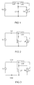
- the ignition devices shown schematically in FIGS. 1 to 9 serve to pressurize the auxiliary ignition electrode Z or Z 'of the high-pressure discharge lamp Lp with the ignition voltage required for this purpose.
- the ignition devices are each fed by an AC voltage source Q or Q ', which generates, for example, a sinusoidal or rectangular supply voltage or a sinusoidal or rectangular supply current.
- the embodiment of the ignition device according to the invention schematically illustrated in Figure 1 consists of an autotransformer L11, L12 and a capacitor C1.
- the autotransformer has a winding having a first winding portion L11 formed as a primary winding and a second winding portion L12, which is designed as a secondary winding of the transformer.
- the capacitor C1 and the primary winding section L11 are connected as a series resonant circuit connected to the AC power source Q.
- the resonant frequency of the series resonant circuit is preferably selected above 300 kHz, in particular above 1 MHz, which results in a small size and a particularly low required voltage at the auxiliary ignition electrode.
- the frequency of the supply voltage or the supply current is selected during the ignition phase near the resonance frequency of the series resonant circuit or selected such that a harmonic of the supply signal leads to an excitation of the series resonant circuit during the ignition phase.
- the center tap between the two winding sections L11, L12, which is formed as a common first terminal of the winding sections L11, L12, is connected both to the first electrode of the high-pressure discharge lamp Lp and to one terminal of the capacitor C1.
- the second terminal of the primary winding section L11 is connected to the AC voltage source Q, while the second terminal of the secondary winding section L12 is connected to the auxiliary starting electrode Z of the high-pressure discharge lamp Lp.
- the capacitor C1 is connected in parallel with the discharge path of the lamp Lp.
- the lamp Lp is, for example, a mercury-free metal halide high-pressure discharge lamp, which is provided as a light source in a vehicle headlight.
- the Entladwigsgefäß this high-pressure discharge lamp Lp consists either of a translucent ceramic, such as alumina ceramic, or quartz glass.
- the auxiliary starting electrode Z is applied for example as an electrically conductive coating on the outside of the discharge vessel or as a wire, so that a capacitive coupling between the Zündangeselektrode Z and at least one of the two disposed within the discharge vessel electrodes of the high pressure discharge lamp Lp.
- the resonance capacitor C1 has a capacitance of 94 pF (measured at a frequency of 1 kHz).
- the primary winding section L11 has 70 turns and an inductance of 100 ⁇ H (measured at a frequency of 1 kHz).
- the secondary winding section L12 has 95 turns.
- an AC voltage source Q which has a nearly sinusoidal AC voltage with an effective value of 90 V and a frequency of 1.248 MHz, which corresponds to the empirically determined resonant frequency of the resonant circuit formed from the components used.
- the AC voltage source Q is a voltage converter, for example a push-pull converter, which generates the desired AC voltage from the vehicle electrical system voltage of the motor vehicle.
- the frequency of the AC voltage provided by the AC source Q is tuned to the resonant frequency of the series resonant circuit C1, L11, so that builds up on the components C1 and L11 a resonance-elevated AC voltage with a peak value of more than 1000 volts.
- This voltage is also applied to the discharge path between the two electrodes of the high-pressure gas discharge lamp Lp, since the resonance capacitor C1 is connected in parallel to the discharge path of the lamp Lp.
- the resonance-boosted AC voltage is transformed up to a peak value of 2500 volts and fed to the auxiliary starting electrode Z.
- the ignition device After ignition of the gas discharge in the high-pressure discharge lamp Lp, the ignition device is automatically deactivated, since the high-pressure discharge lamp then strongly attenuates the resonant circuit.
- the frequency of the AC voltage generated by the AC voltage source Q is increased so far that sets the desired lamp power.
- the primary winding section L11 is used for stabilizing the discharge, that is, limiting the lamp current.
- an alternating voltage source Q For operating the abovementioned high-pressure discharge lamp Lp with a discharge vessel made of quartz glass, an alternating voltage source Q is used, which has a nearly sinusoidal alternating voltage with an effective value of 195 V and a Has a frequency of 1.234 MHz.
- the frequency of the AC voltage provided by the AC voltage source Q is tuned to the resonant frequency of the series resonant circuit C1, L11, so that builds up on the components C1 and L11 a resonance-elevated AC voltage with a peak value of 1500 volts.
- This voltage is also applied to the discharge path between the two electrodes of the high-pressure gas discharge lamp Lp, since the resonance capacitor C1 is connected in parallel to the discharge path of the lamp Lp.
- the ignition assisting electrode Z is supplied with an alternating voltage having a peak value of 4000 volts. There is therefore a voltage difference of 4000 volts between the auxiliary starting electrode Z and the electrode of the high-pressure discharge lamp Lp connected to the AC voltage source Q and one terminal of the resonance capacitor C1, which is sufficient together with the voltage difference between the electrodes for igniting the gas discharge in the lamp Lp.
- the ignition device After ignition of the gas discharge in the Hochlichentladungsiampe Lp the ignition device is automatically deactivated because the high-pressure discharge lamp then strongly attenuates the resonant circuit.
- the frequency of the AC voltage generated by the AC voltage source Q is increased so far that sets the desired lamp power.
- the primary winding section L11 is used for stabilizing the discharge, that is, limiting the lamp current.
- a frequency modulation of the alternating voltage can be carried out during the ignition phase.
- a frequency sweep of 50 kHz and a sinusoidal modulation signal of 500 Hz are suitable for this purpose.
- the ignition device consists of an autotransformer L21, L22 and a capacitor C2.
- the autotransformer has a winding having a first winding portion L21 formed as a primary winding and a second winding portion L22 formed as a secondary winding of the transformer.
- the capacitor C2 and the primary winding section L21 are connected as a series resonant circuit which is connected to the AC voltage source Q.
- the center tap between the two winding sections L21, L22, which is formed as a common first terminal of the winding sections L21, L22, is connected both to the first electrode of the high-pressure discharge lamp Lp and to one terminal of the capacitor C2.
- the second terminal of the primary winding section L21 is connected to the AC power source Q and to the second electrode of the high pressure discharge lamp, while the second terminal of the secondary winding section L22 is connected to the auxiliary starting electrode Z of the high pressure discharge lamp Lp.
- the primary winding section L21 and not the resonance capacitor C2 are connected in parallel to the discharge path of the high-pressure discharge lamp Lp.
- the winding sections L21, L22 and the resonance capacitor C2 have the same dimension as the corresponding components L11, L12 and C1 of the first embodiment.
- the AC power source Q and the lamp Lp are also the same as the first embodiment.
- the capacitor C2 also prevents a DC flow through the lamp Lp.
- the resonance capacitor C2 has a capacity of 94 pF.
- the primary winding section L21 has 70 turns and an inductance of 100 ⁇ H.
- the secondary winding section L22 has 95 turns.
- the frequency of the AC voltage generated by the AC voltage source Q is linearly increased from 1.2 MHz to 1.3 MHz within 1 millisecond and then reduced again within the same time to 1.2 MHz to ensure in that the resonant frequency of the series resonant circuit C2, L21 lying in this frequency range is hit sufficiently well. This procedure is repeated until the gas discharge in the lamp Lp has ignited or a predetermined maximum period of time, For example, 100 ms, is exceeded and the AC voltage source Q is turned off. After the ignition of the gas discharge in the lamp Lp, the frequency of the alternating voltage is increased until the desired lamp power is established.
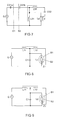
- a third embodiment of the ignition device according to the invention is shown.
- the third embodiment is largely consistent with the ignition device according to the second embodiment.
- the resonance capacity of the series resonant circuit of the ignition device is formed by two capacitors C31 and C32.
- the two resonance capacitors C31, C32 are connected in such a way that a complete potential separation between the AC voltage source Q and the components of the ignition device and the lamp Lp is ensured.
- the capacitor C31 has a capacitance of 235 pF and the capacitor C32 has a capacitance of 157 pF.
- the dimensioning and arrangement of the components L31, L32, Q, Lp and Z coincides with the dimensioning and arrangement of the components L21, L22, Q, Lp and Z of the second embodiment (see Figure 2).
- the operation also corresponds to that of the second embodiment.
- the illustrated in Figure 4 fourth embodiment of the ignition device according to the invention differs from the first embodiment only by the additional DC voltage isolation capacitor C42, which is connected between the high voltage output of the secondary winding section L42 and the auxiliary ignition Z of the high pressure discharge lamp Lp.
- the primary winding section L41 of the auto-transformer L41, L42 and the capacitor C41 form a series resonant circuit connected to the AC power source Q.
- the resonance capacitor C41 is connected in parallel with the discharge path of the high-pressure discharge lamp Lp.
- the center tap between the primary L41 and the secondary winding section L42 is connected to the capacitor C41 and to the first electrode of the high pressure discharge lamp Lp.
- the other terminal of the secondary winding section L42 is connected to the auxiliary starting electrode via the capacitor C42 Z connected.
- the second electrode of the lamp Lp is connected to the capacitor C41 and to the AC voltage source Q.
- the capacitor C42 prevents a direct current flow between the auxiliary starting electrode and the first and second electrodes of the high pressure discharge lamp Lp.
- the capacitance of the capacitor C42 can be freely selected within wide limits, without exerting a significant influence on the ignition process.
- the capacitor C42 is dimensioned such that the voltage drop across the capacitor C42 during the ignition process is smaller than the voltages that occur between the auxiliary starting electrode Z and the two electrodes of the high-pressure discharge lamp Lp. Therefore, very small capacitance values are sufficient for the capacitor C42, for example 33 pF. But also significantly larger values for the capacitance of the capacitor C42 such as 10 nF are possible.
- the operation of this embodiment corresponds to that of the first embodiment.
- the illustrated in Figure 5 fifth embodiment corresponds substantially to the illustrated in Figure 2 second embodiment of the invention. It differs from the second embodiment only by the additional DC voltage isolation capacitor C52, which is connected between the Zünclangesektrode Z and the high voltage terminal of the secondary winding section L52.
- the capacitor C5 1 and the primary winding portion L5 1 of the autotransformer L51, L52 form a series resonant circuit which is connected to the AC voltage source Q.
- the primary winding section L51 is connected in parallel to the discharge path of the high-pressure discharge lamp Lp.
- the arrangement and dimensioning of the components L51, L52, C51, Q, Lp and Z corresponds to the arrangement and dimensioning of the components L21, L22, C2, Q, Lp and Z of the second embodiment ( Figure 2) of the invention.
- the operation also corresponds to that of the second embodiment of the invention.
- FIG 6 the spatial distribution of the components of the ignition device according to the fifth embodiment ( Figure 5) is shown schematically.
- the components C51, L51, L52 and C52 of the igniter are housed in the lamp cap of the high pressure discharge lamp Lp.
- the electrical connections S2 of High-pressure discharge lamp Lp or the ignition device are connected by means of cables to the electrical terminals S1 of the AC voltage source Q.
- FIG. 7 schematically shows an alternative spatial distribution of the resonant capacitance of the series resonant circuit of the ignition device according to the invention.
- the resonant capacitance here consists of the two series-connected capacitors C51a and C51b.
- the capacitors C51a, C51b and the primary winding portion L51 of the autotransformer L51, L52 form a series resonant circuit connected to the AC power source Q here.
- the capacitors C51a, C51b here replace the capacitor C51 according to the fifth embodiment shown in FIGS. 5 and 6.
- the capacitor C51a is formed as a component of the AC voltage source or the ballast Q of the lamp Lp, while the capacitor C51b formed as part of the ignition device is housed together with the other components of the ignition device in the lamp base of the lamp Lp.
- the embodiment illustrated in Figure 7 corresponds to the fifth embodiment shown in Figures 5 and 6. For identical components, therefore, the same reference numerals have been used in Figures 5, 6 and 7.
- FIGS. 8 and 9 again show the ignition device according to the first exemplary embodiment of the invention and with the high-pressure discharge lamp Lp.
- the lamp Lp is here, however, provided with differently designed Zündangeselektroden Z1, or Z2. Therefore, the same reference numerals have been used in Figures 1, 8 and 9 for identical components.
- the auxiliary starting electrode Z1 is designed as a wire which protrudes into the interior of the outer bulb B 1 and bears against the outside of the discharge gap B2.
- the Zündisdraht Z1 is capacitively coupled to one of the electrodes disposed within the discharge vessel B2 of the high pressure discharge lamp Lp and led out of the Außcnkolben B 1 via a seal, such as a pinch seal and contacted with the high voltage terminal of the secondary winding section L 12.
- the auxiliary starting electrode Z1 consists essentially of a spring plate, which is arranged in the interior of the outer bulb B1 and capacitively coupled to one of the electrodes arranged inside the discharge vessel B2.
- the spring plate is contacted with a metallic layer on the inside of the outer bulb B2, which in turn is capacitively coupled to a second coating on the outside of the outer bulb B1.
- the two metallic coatings on the inside and outside of the outer bulb B1 face each other and form a capacitor in which the material or glass of the outer bulb forms the dielectric. This capacitor corresponds to the DC voltage isolation capacitor C52.
- the metallic coating on the outside of the outer bulb B1 is connected to the high voltage terminal of the secondary winding portion L12.
Landscapes
- Circuit Arrangements For Discharge Lamps (AREA)
- Discharge-Lamp Control Circuits And Pulse- Feed Circuits (AREA)
- Discharge Lamps And Accessories Thereof (AREA)
Applications Claiming Priority (1)
| Application Number | Priority Date | Filing Date | Title |
|---|---|---|---|
| DE102004052299A DE102004052299A1 (de) | 2004-10-27 | 2004-10-27 | Zündvorrichtung für eine Hochdruckentlandungslampe und Hochdruckentladungslampe mit Zündvorrichtung sowie Betriebsverfahren für eine Hochdruckentladungslampe |
Publications (2)
| Publication Number | Publication Date |
|---|---|
| EP1653785A1 true EP1653785A1 (fr) | 2006-05-03 |
| EP1653785B1 EP1653785B1 (fr) | 2009-07-29 |
Family
ID=35295411
Family Applications (1)
| Application Number | Title | Priority Date | Filing Date |
|---|---|---|---|
| EP05022448A Expired - Lifetime EP1653785B1 (fr) | 2004-10-27 | 2005-10-14 | Dispositif d'allumage pour une lampe a decharge haute pression et une lampe a décharge haute pression avec un dispositif d'allumage et méthode d'opération. |
Country Status (7)
| Country | Link |
|---|---|
| US (1) | US7378800B2 (fr) |
| EP (1) | EP1653785B1 (fr) |
| JP (1) | JP4915642B2 (fr) |
| CN (1) | CN1805642B (fr) |
| AT (1) | ATE438285T1 (fr) |
| DE (2) | DE102004052299A1 (fr) |
| ES (1) | ES2328706T3 (fr) |
Cited By (1)
| Publication number | Priority date | Publication date | Assignee | Title |
|---|---|---|---|---|
| WO2007004191A1 (fr) * | 2005-07-06 | 2007-01-11 | Koninklijke Philips Electronics N.V. | Allumage pour lampe a decharge |
Families Citing this family (7)
| Publication number | Priority date | Publication date | Assignee | Title |
|---|---|---|---|---|
| CA2604456A1 (fr) * | 2005-04-14 | 2006-10-19 | Patent-Treuhand-Gesellschaft Fuer Elektrische Gluehlampen Mbh | Dispositif d'allumage d'electrode auxiliaire d'allumage a eclateur |
| JP5225168B2 (ja) * | 2009-03-23 | 2013-07-03 | 三菱電機株式会社 | 点弧補助電極付き放電灯の点灯装置 |
| WO2010121964A1 (fr) | 2009-04-24 | 2010-10-28 | Osram Gesellschaft mit beschränkter Haftung | Unité coupleur-lampe pour lampes à décharge haute intensité sans électrode (ehid) pourvue d'une mémoire et communication de données et d'une traversée commandée en impédance, et système de décharge haute intensité sans électrode pourvu d'une telle unité coupleur-lampe |
| KR20130138215A (ko) * | 2010-09-22 | 2013-12-18 | 오스람 게엠베하 | 고압 방전 램프를 시동시키기 위한 방법 |
| US8339044B2 (en) | 2010-12-28 | 2012-12-25 | General Electric Company | Mercury-free ceramic metal halide lamp with improved lumen run-up |
| CN106714432A (zh) * | 2016-12-29 | 2017-05-24 | 吴文武 | 不用启辉器的纯电感镇流器 |
| CN117927876B (zh) * | 2024-03-01 | 2025-06-27 | 浙江奇爱管业有限公司 | 一种燃气管道的漏电报警方法 |
Citations (4)
| Publication number | Priority date | Publication date | Assignee | Title |
|---|---|---|---|---|
| EP0868833A1 (fr) * | 1996-10-23 | 1998-10-07 | Patent-Treuhand-Gesellschaft für elektrische Glühlampen mbH | Lampe a decharge haute pression a electrode auxiliaire d'amor age, ainsi que circuit et procede pour son fonctionnement |
| US6104141A (en) * | 1997-09-01 | 2000-08-15 | U.S. Philips Corporation | Inventer-ballast using a piezoelectric transformer |
| EP1241925A2 (fr) * | 2001-03-13 | 2002-09-18 | Ushiodenki Kabushiki Kaisha | Appareil d' éclairage |
| EP1345478A2 (fr) * | 2002-03-12 | 2003-09-17 | Patent-Treuhand-Gesellschaft für elektrische Glühlampen mbH | Circuit pour amorcer des lampes à décharge haute-pression |
Family Cites Families (16)
| Publication number | Priority date | Publication date | Assignee | Title |
|---|---|---|---|---|
| US2508114A (en) * | 1947-12-05 | 1950-05-16 | Gen Electric | Tantalum electrode for electric discharge devices |
| NL7108465A (fr) * | 1970-06-24 | 1971-12-28 | ||
| JPS56109495A (en) * | 1980-01-31 | 1981-08-29 | Nippon Electric Co | Device for firing discharge lamp |
| EP0181666B1 (fr) * | 1984-11-06 | 1990-01-03 | Koninklijke Philips Electronics N.V. | Lampe à décharge haute-pression |
| GB2172451B (en) * | 1985-02-07 | 1989-06-14 | El Co Villamos Keszulekek Es S | Circuit system for igniting and lighting a high-pressure discharge lamp particulary a sodium vapour lamp |
| DE3719356A1 (de) | 1987-06-10 | 1988-12-29 | Patent Treuhand Ges Fuer Elektrische Gluehlampen Mbh | Schaltungsanordnung zum betrieb einer entladungslampe an einer niedervolt-gleichspannungsquelle |
| JP3396908B2 (ja) * | 1993-04-09 | 2003-04-14 | 松下電器産業株式会社 | ラインフィルタ |
| JPH06311754A (ja) * | 1993-04-23 | 1994-11-04 | Matsushita Electric Works Ltd | インバータ装置 |
| CA2145894A1 (fr) * | 1994-04-18 | 1995-10-19 | Louis R. Nerone | Metallisation de la surface exterieure de l'enveloppe d'une lampe fluorescente sans electrode |
| JP3355976B2 (ja) * | 1997-02-05 | 2002-12-09 | ウシオ電機株式会社 | 放電ランプ点灯装置 |
| DE19923237A1 (de) * | 1999-05-20 | 2000-11-23 | Patent Treuhand Ges Fuer Elektrische Gluehlampen Mbh | Schaltungsanordnung, zugeordnetes elektrisches System sowie Entladungslampe mit derartiger Schaltungsanordnung und Verfahren zu ihrem Betrieb |
| DE19923265A1 (de) * | 1999-05-20 | 2000-11-23 | Patent Treuhand Ges Fuer Elektrische Gluehlampen Mbh | Schaltungsanordnung zur Zündung und zum Betrieb von Hochdrucklampen |
| JP3291275B2 (ja) * | 1999-09-30 | 2002-06-10 | 松下電工株式会社 | 放電灯点灯装置 |
| JP2006513539A (ja) * | 2003-01-14 | 2006-04-20 | コーニンクレッカ フィリップス エレクトロニクス エヌ ヴィ | 回路配置 |
| DE10331435A1 (de) * | 2003-07-10 | 2005-02-10 | Patent-Treuhand-Gesellschaft für elektrische Glühlampen mbH | Zündvorrichtung für eine Hochdruckentladungslampe und Beleuchtungssystem |
| DE10333729A1 (de) * | 2003-07-23 | 2005-03-10 | Patent Treuhand Ges Fuer Elektrische Gluehlampen Mbh | Vorschaltgerät für mindestens eine Hochdruckentladungslampe, Betriebsverfahren und Beleuchtungssytem für eine Hochdruckentladungslampe |
-
2004
- 2004-10-27 DE DE102004052299A patent/DE102004052299A1/de not_active Withdrawn
-
2005
- 2005-10-14 ES ES05022448T patent/ES2328706T3/es not_active Expired - Lifetime
- 2005-10-14 AT AT05022448T patent/ATE438285T1/de not_active IP Right Cessation
- 2005-10-14 DE DE502005007770T patent/DE502005007770D1/de not_active Expired - Lifetime
- 2005-10-14 EP EP05022448A patent/EP1653785B1/fr not_active Expired - Lifetime
- 2005-10-18 US US11/251,885 patent/US7378800B2/en not_active Expired - Fee Related
- 2005-10-27 CN CN2005101283314A patent/CN1805642B/zh not_active Expired - Fee Related
- 2005-10-27 JP JP2005312860A patent/JP4915642B2/ja not_active Expired - Fee Related
Patent Citations (4)
| Publication number | Priority date | Publication date | Assignee | Title |
|---|---|---|---|---|
| EP0868833A1 (fr) * | 1996-10-23 | 1998-10-07 | Patent-Treuhand-Gesellschaft für elektrische Glühlampen mbH | Lampe a decharge haute pression a electrode auxiliaire d'amor age, ainsi que circuit et procede pour son fonctionnement |
| US6104141A (en) * | 1997-09-01 | 2000-08-15 | U.S. Philips Corporation | Inventer-ballast using a piezoelectric transformer |
| EP1241925A2 (fr) * | 2001-03-13 | 2002-09-18 | Ushiodenki Kabushiki Kaisha | Appareil d' éclairage |
| EP1345478A2 (fr) * | 2002-03-12 | 2003-09-17 | Patent-Treuhand-Gesellschaft für elektrische Glühlampen mbH | Circuit pour amorcer des lampes à décharge haute-pression |
Cited By (2)
| Publication number | Priority date | Publication date | Assignee | Title |
|---|---|---|---|---|
| WO2007004191A1 (fr) * | 2005-07-06 | 2007-01-11 | Koninklijke Philips Electronics N.V. | Allumage pour lampe a decharge |
| US8022644B2 (en) | 2005-07-06 | 2011-09-20 | Koninklijke Philips Electronics N.V. | Gas discharge lamp ignition |
Also Published As
| Publication number | Publication date |
|---|---|
| CN1805642B (zh) | 2010-09-29 |
| ATE438285T1 (de) | 2009-08-15 |
| JP4915642B2 (ja) | 2012-04-11 |
| US7378800B2 (en) | 2008-05-27 |
| JP2006128113A (ja) | 2006-05-18 |
| EP1653785B1 (fr) | 2009-07-29 |
| DE502005007770D1 (de) | 2009-09-10 |
| DE102004052299A1 (de) | 2006-05-04 |
| ES2328706T3 (es) | 2009-11-17 |
| CN1805642A (zh) | 2006-07-19 |
| US20060087251A1 (en) | 2006-04-27 |
Similar Documents
| Publication | Publication Date | Title |
|---|---|---|
| DE102018204587B4 (de) | Verfahren zur Zündung eines Plasmas in einer Plasmakammer und Zündschaltung | |
| EP0868833B1 (fr) | Lampe a decharge haute pression a electrode auxiliaire d'amor age, ainsi que circuit et procede pour son fonctionnement | |
| DE3221701C2 (fr) | ||
| EP1653785B1 (fr) | Dispositif d'allumage pour une lampe a decharge haute pression et une lampe a décharge haute pression avec un dispositif d'allumage et méthode d'opération. | |
| EP2100484A1 (fr) | Dispositif d'allumage pour une lampe à décharge à haute pression et lampe à décharge à haute pression avec dispositif d'allumage | |
| EP2529597B1 (fr) | Procédé permettant de faire fonctionner une lampe à décharge de gaz et système de lampe à décharge de gaz | |
| DE102014116586B4 (de) | Korona-Zündsystem für einen Verbrennungsmotor | |
| EP1869951A1 (fr) | Dispositif d'amorçage a transformateur piezoelectrique pour une lampe a decharge a haute pression | |
| EP1659835B1 (fr) | Lamp à décharge haute pression avec un circuit d'amorçage par impulsion et méthode de commande pour une telle lampe | |
| EP1243165B1 (fr) | Montage de circuits permettant le fonctionnement d'une lampe a decharge gazeuse | |
| EP1869954A1 (fr) | Dispositif pour faire fonctionner ou allumer une lampe a decharge a haute pression, culot de lampe et systeme d'eclairage presentant un tel dispositif et procede pour faire fonctionner une lampe a decharge a haute pression | |
| EP1894448B1 (fr) | Dispositif et procede permettant de faire fonctionner une lampe a decharge haute pression | |
| DE10331435A1 (de) | Zündvorrichtung für eine Hochdruckentladungslampe und Beleuchtungssystem | |
| DE102005035745A1 (de) | Zündschaltung zum Zünden einer Entladungslampe und Verfahren zum Zünden der Entladungslampe | |
| WO2004054327A1 (fr) | Montage electrique pour allumer une lampe a decharge et procede pour allumer la lampe a decharge | |
| EP2448376A2 (fr) | Appareil de montage électronique et appareil d'éclairage | |
| WO2006108407A1 (fr) | Dispositif d'allumage d'electrode auxiliaire d'allumage a eclateur | |
| DE102005023798A1 (de) | Vorrichtung zum Betreiben oder Zünden einer Hochdruckentladungslampe, Lampensockel und Beleuchtungssystem mit einer derartigen Vorrichtung sowie Verfahren zum Betreiben einer Hochdruckentladungslampe | |
| DE102008051824A1 (de) | Zündvorrichtung für eine Entladungslampe sowie Entladungslampe | |
| DE102006028821A1 (de) | Vorrichtung und Verfahren zum Betreiben einer Hochdruckentladungslampe | |
| DE102005020773A1 (de) | Vorrichtung zum Betreiben oder Zünden einer Hochdruckentladungslampe, Lampensockel und Beleuchtungssystem mit einer derartigen Vorrichtung sowie Verfahren zum Betreiben einer Hochdruckentladungslampe | |
| DD149987A5 (de) | Steuerstromkreis fuer gasentladungslampen | |
| DE102010029146A1 (de) | Schaltungsanordnung zum Zünden von Hochdruckentladungslampen | |
| DE102009052702A1 (de) | Schaltungsanordnung zum Betreiben einer Entladungslampe | |
| DE102005052555A1 (de) | Zündvorrichtung für eine Hochdruckentladungslampe und Betriebsgerät für eine Hochdruckentladungslampe mit einer Zündvorrichtung |
Legal Events
| Date | Code | Title | Description |
|---|---|---|---|
| PUAI | Public reference made under article 153(3) epc to a published international application that has entered the european phase |
Free format text: ORIGINAL CODE: 0009012 |
|
| AK | Designated contracting states |
Kind code of ref document: A1 Designated state(s): AT BE BG CH CY CZ DE DK EE ES FI FR GB GR HU IE IS IT LI LT LU LV MC NL PL PT RO SE SI SK TR |
|
| AX | Request for extension of the european patent |
Extension state: AL BA HR MK YU |
|
| 17P | Request for examination filed |
Effective date: 20060606 |
|
| R17C | First examination report despatched (corrected) |
Effective date: 20060706 |
|
| AKX | Designation fees paid |
Designated state(s): AT BE BG CH CY CZ DE DK EE ES FI FR GB GR HU IE IS IT LI LT LU LV MC NL PL PT RO SE SI SK TR |
|
| 17Q | First examination report despatched |
Effective date: 20060706 |
|
| RAP1 | Party data changed (applicant data changed or rights of an application transferred) |
Owner name: OSRAM GESELLSCHAFT MIT BESCHRAENKTER HAFTUNG |
|
| GRAP | Despatch of communication of intention to grant a patent |
Free format text: ORIGINAL CODE: EPIDOSNIGR1 |
|
| GRAS | Grant fee paid |
Free format text: ORIGINAL CODE: EPIDOSNIGR3 |
|
| GRAA | (expected) grant |
Free format text: ORIGINAL CODE: 0009210 |
|
| AK | Designated contracting states |
Kind code of ref document: B1 Designated state(s): AT BE BG CH CY CZ DE DK EE ES FI FR GB GR HU IE IS IT LI LT LU LV MC NL PL PT RO SE SI SK TR |
|
| REG | Reference to a national code |
Ref country code: GB Ref legal event code: FG4D Free format text: NOT ENGLISH |
|
| REG | Reference to a national code |
Ref country code: CH Ref legal event code: EP |
|
| REG | Reference to a national code |
Ref country code: IE Ref legal event code: FG4D |
|
| REF | Corresponds to: |
Ref document number: 502005007770 Country of ref document: DE Date of ref document: 20090910 Kind code of ref document: P |
|
| REG | Reference to a national code |
Ref country code: ES Ref legal event code: FG2A Ref document number: 2328706 Country of ref document: ES Kind code of ref document: T3 |
|
| REG | Reference to a national code |
Ref country code: SE Ref legal event code: TRGR |
|
| PG25 | Lapsed in a contracting state [announced via postgrant information from national office to epo] |
Ref country code: IS Free format text: LAPSE BECAUSE OF FAILURE TO SUBMIT A TRANSLATION OF THE DESCRIPTION OR TO PAY THE FEE WITHIN THE PRESCRIBED TIME-LIMIT Effective date: 20091129 Ref country code: FI Free format text: LAPSE BECAUSE OF FAILURE TO SUBMIT A TRANSLATION OF THE DESCRIPTION OR TO PAY THE FEE WITHIN THE PRESCRIBED TIME-LIMIT Effective date: 20090729 Ref country code: LT Free format text: LAPSE BECAUSE OF FAILURE TO SUBMIT A TRANSLATION OF THE DESCRIPTION OR TO PAY THE FEE WITHIN THE PRESCRIBED TIME-LIMIT Effective date: 20090729 |
|
| PG25 | Lapsed in a contracting state [announced via postgrant information from national office to epo] |
Ref country code: SI Free format text: LAPSE BECAUSE OF FAILURE TO SUBMIT A TRANSLATION OF THE DESCRIPTION OR TO PAY THE FEE WITHIN THE PRESCRIBED TIME-LIMIT Effective date: 20090729 Ref country code: PL Free format text: LAPSE BECAUSE OF FAILURE TO SUBMIT A TRANSLATION OF THE DESCRIPTION OR TO PAY THE FEE WITHIN THE PRESCRIBED TIME-LIMIT Effective date: 20090729 Ref country code: LV Free format text: LAPSE BECAUSE OF FAILURE TO SUBMIT A TRANSLATION OF THE DESCRIPTION OR TO PAY THE FEE WITHIN THE PRESCRIBED TIME-LIMIT Effective date: 20090729 |
|
| REG | Reference to a national code |
Ref country code: HU Ref legal event code: AG4A Ref document number: E006539 Country of ref document: HU |
|
| REG | Reference to a national code |
Ref country code: IE Ref legal event code: FD4D |
|
| PG25 | Lapsed in a contracting state [announced via postgrant information from national office to epo] |
Ref country code: PT Free format text: LAPSE BECAUSE OF FAILURE TO SUBMIT A TRANSLATION OF THE DESCRIPTION OR TO PAY THE FEE WITHIN THE PRESCRIBED TIME-LIMIT Effective date: 20091129 Ref country code: BG Free format text: LAPSE BECAUSE OF FAILURE TO SUBMIT A TRANSLATION OF THE DESCRIPTION OR TO PAY THE FEE WITHIN THE PRESCRIBED TIME-LIMIT Effective date: 20091029 |
|
| PG25 | Lapsed in a contracting state [announced via postgrant information from national office to epo] |
Ref country code: RO Free format text: LAPSE BECAUSE OF FAILURE TO SUBMIT A TRANSLATION OF THE DESCRIPTION OR TO PAY THE FEE WITHIN THE PRESCRIBED TIME-LIMIT Effective date: 20090729 Ref country code: EE Free format text: LAPSE BECAUSE OF FAILURE TO SUBMIT A TRANSLATION OF THE DESCRIPTION OR TO PAY THE FEE WITHIN THE PRESCRIBED TIME-LIMIT Effective date: 20090729 Ref country code: CZ Free format text: LAPSE BECAUSE OF FAILURE TO SUBMIT A TRANSLATION OF THE DESCRIPTION OR TO PAY THE FEE WITHIN THE PRESCRIBED TIME-LIMIT Effective date: 20090729 Ref country code: DK Free format text: LAPSE BECAUSE OF FAILURE TO SUBMIT A TRANSLATION OF THE DESCRIPTION OR TO PAY THE FEE WITHIN THE PRESCRIBED TIME-LIMIT Effective date: 20090729 Ref country code: IE Free format text: LAPSE BECAUSE OF FAILURE TO SUBMIT A TRANSLATION OF THE DESCRIPTION OR TO PAY THE FEE WITHIN THE PRESCRIBED TIME-LIMIT Effective date: 20090729 |
|
| PG25 | Lapsed in a contracting state [announced via postgrant information from national office to epo] |
Ref country code: SK Free format text: LAPSE BECAUSE OF FAILURE TO SUBMIT A TRANSLATION OF THE DESCRIPTION OR TO PAY THE FEE WITHIN THE PRESCRIBED TIME-LIMIT Effective date: 20090729 Ref country code: MC Free format text: LAPSE BECAUSE OF NON-PAYMENT OF DUE FEES Effective date: 20091031 |
|
| REG | Reference to a national code |
Ref country code: CH Ref legal event code: PL |
|
| PLBE | No opposition filed within time limit |
Free format text: ORIGINAL CODE: 0009261 |
|
| STAA | Information on the status of an ep patent application or granted ep patent |
Free format text: STATUS: NO OPPOSITION FILED WITHIN TIME LIMIT |
|
| 26N | No opposition filed |
Effective date: 20100503 |
|
| PG25 | Lapsed in a contracting state [announced via postgrant information from national office to epo] |
Ref country code: LI Free format text: LAPSE BECAUSE OF NON-PAYMENT OF DUE FEES Effective date: 20091031 Ref country code: GR Free format text: LAPSE BECAUSE OF FAILURE TO SUBMIT A TRANSLATION OF THE DESCRIPTION OR TO PAY THE FEE WITHIN THE PRESCRIBED TIME-LIMIT Effective date: 20091030 Ref country code: CH Free format text: LAPSE BECAUSE OF NON-PAYMENT OF DUE FEES Effective date: 20091031 |
|
| PG25 | Lapsed in a contracting state [announced via postgrant information from national office to epo] |
Ref country code: AT Free format text: LAPSE BECAUSE OF NON-PAYMENT OF DUE FEES Effective date: 20091014 |
|
| PGFP | Annual fee paid to national office [announced via postgrant information from national office to epo] |
Ref country code: HU Payment date: 20101217 Year of fee payment: 6 |
|
| PGFP | Annual fee paid to national office [announced via postgrant information from national office to epo] |
Ref country code: IT Payment date: 20101027 Year of fee payment: 6 Ref country code: GB Payment date: 20101018 Year of fee payment: 6 Ref country code: BE Payment date: 20101117 Year of fee payment: 6 |
|
| PG25 | Lapsed in a contracting state [announced via postgrant information from national office to epo] |
Ref country code: LU Free format text: LAPSE BECAUSE OF NON-PAYMENT OF DUE FEES Effective date: 20091014 |
|
| PG25 | Lapsed in a contracting state [announced via postgrant information from national office to epo] |
Ref country code: TR Free format text: LAPSE BECAUSE OF FAILURE TO SUBMIT A TRANSLATION OF THE DESCRIPTION OR TO PAY THE FEE WITHIN THE PRESCRIBED TIME-LIMIT Effective date: 20090729 |
|
| PG25 | Lapsed in a contracting state [announced via postgrant information from national office to epo] |
Ref country code: CY Free format text: LAPSE BECAUSE OF FAILURE TO SUBMIT A TRANSLATION OF THE DESCRIPTION OR TO PAY THE FEE WITHIN THE PRESCRIBED TIME-LIMIT Effective date: 20090729 |
|
| PGFP | Annual fee paid to national office [announced via postgrant information from national office to epo] |
Ref country code: ES Payment date: 20111108 Year of fee payment: 7 Ref country code: FR Payment date: 20111024 Year of fee payment: 7 Ref country code: SE Payment date: 20111020 Year of fee payment: 7 Ref country code: NL Payment date: 20111020 Year of fee payment: 7 |
|
| REG | Reference to a national code |
Ref country code: DE Ref legal event code: R081 Ref document number: 502005007770 Country of ref document: DE Owner name: OSRAM GMBH, DE Free format text: FORMER OWNER: OSRAM GESELLSCHAFT MIT BESCHRAENKTER HAFTUNG, 81543 MUENCHEN, DE Effective date: 20111213 |
|
| BERE | Be: lapsed |
Owner name: OSRAM G.M.B.H. Effective date: 20111031 |
|
| PG25 | Lapsed in a contracting state [announced via postgrant information from national office to epo] |
Ref country code: BE Free format text: LAPSE BECAUSE OF NON-PAYMENT OF DUE FEES Effective date: 20111031 Ref country code: HU Free format text: LAPSE BECAUSE OF NON-PAYMENT OF DUE FEES Effective date: 20111015 |
|
| REG | Reference to a national code |
Ref country code: DE Ref legal event code: R081 Ref document number: 502005007770 Country of ref document: DE Owner name: OSRAM GMBH, DE Free format text: FORMER OWNER: OSRAM AG, 81543 MUENCHEN, DE Effective date: 20130205 |
|
| REG | Reference to a national code |
Ref country code: NL Ref legal event code: V1 Effective date: 20130501 |
|
| GBPC | Gb: european patent ceased through non-payment of renewal fee |
Effective date: 20121014 |
|
| REG | Reference to a national code |
Ref country code: FR Ref legal event code: ST Effective date: 20130628 |
|
| PG25 | Lapsed in a contracting state [announced via postgrant information from national office to epo] |
Ref country code: SE Free format text: LAPSE BECAUSE OF NON-PAYMENT OF DUE FEES Effective date: 20121015 Ref country code: GB Free format text: LAPSE BECAUSE OF NON-PAYMENT OF DUE FEES Effective date: 20121014 |
|
| PG25 | Lapsed in a contracting state [announced via postgrant information from national office to epo] |
Ref country code: IT Free format text: LAPSE BECAUSE OF NON-PAYMENT OF DUE FEES Effective date: 20121014 Ref country code: NL Free format text: LAPSE BECAUSE OF NON-PAYMENT OF DUE FEES Effective date: 20130501 Ref country code: FR Free format text: LAPSE BECAUSE OF NON-PAYMENT OF DUE FEES Effective date: 20121031 |
|
| REG | Reference to a national code |
Ref country code: DE Ref legal event code: R081 Ref document number: 502005007770 Country of ref document: DE Owner name: OSRAM GMBH, DE Free format text: FORMER OWNER: OSRAM GMBH, 81543 MUENCHEN, DE Effective date: 20130823 |
|
| REG | Reference to a national code |
Ref country code: ES Ref legal event code: FD2A Effective date: 20140527 |
|
| PG25 | Lapsed in a contracting state [announced via postgrant information from national office to epo] |
Ref country code: ES Free format text: LAPSE BECAUSE OF NON-PAYMENT OF DUE FEES Effective date: 20121015 |
|
| PGFP | Annual fee paid to national office [announced via postgrant information from national office to epo] |
Ref country code: DE Payment date: 20171019 Year of fee payment: 13 |
|
| REG | Reference to a national code |
Ref country code: DE Ref legal event code: R119 Ref document number: 502005007770 Country of ref document: DE |
|
| PG25 | Lapsed in a contracting state [announced via postgrant information from national office to epo] |
Ref country code: DE Free format text: LAPSE BECAUSE OF NON-PAYMENT OF DUE FEES Effective date: 20190501 |