EP1654068B1 - Dispositif de microdosage et procede de delivrance dosee de liquides - Google Patents
Dispositif de microdosage et procede de delivrance dosee de liquides Download PDFInfo
- Publication number
- EP1654068B1 EP1654068B1 EP04764062A EP04764062A EP1654068B1 EP 1654068 B1 EP1654068 B1 EP 1654068B1 EP 04764062 A EP04764062 A EP 04764062A EP 04764062 A EP04764062 A EP 04764062A EP 1654068 B1 EP1654068 B1 EP 1654068B1
- Authority
- EP
- European Patent Office
- Prior art keywords
- displacer
- fluid conduit
- volume
- outlet opening
- tube
- Prior art date
- Legal status (The legal status is an assumption and is not a legal conclusion. Google has not performed a legal analysis and makes no representation as to the accuracy of the status listed.)
- Expired - Lifetime
Links
- 239000007788 liquid Substances 0.000 title claims abstract description 74
- 238000000034 method Methods 0.000 title claims abstract description 42
- 239000012530 fluid Substances 0.000 claims abstract description 121
- 230000008859 change Effects 0.000 claims description 46
- 230000000694 effects Effects 0.000 claims description 16
- 239000004642 Polyimide Substances 0.000 claims description 11
- 229920001721 polyimide Polymers 0.000 claims description 11
- 230000008569 process Effects 0.000 claims description 9
- 230000003068 static effect Effects 0.000 claims description 5
- 230000004323 axial length Effects 0.000 claims description 3
- 230000000284 resting effect Effects 0.000 claims 2
- 238000006073 displacement reaction Methods 0.000 description 16
- 229920000642 polymer Polymers 0.000 description 13
- 230000007246 mechanism Effects 0.000 description 6
- 239000000758 substrate Substances 0.000 description 6
- 239000012528 membrane Substances 0.000 description 5
- 238000005086 pumping Methods 0.000 description 5
- 230000008901 benefit Effects 0.000 description 4
- 229920005570 flexible polymer Polymers 0.000 description 4
- 238000010586 diagram Methods 0.000 description 3
- 238000004519 manufacturing process Methods 0.000 description 3
- 230000000737 periodic effect Effects 0.000 description 3
- 230000009467 reduction Effects 0.000 description 3
- 238000013459 approach Methods 0.000 description 2
- 230000015572 biosynthetic process Effects 0.000 description 2
- 230000008878 coupling Effects 0.000 description 2
- 238000010168 coupling process Methods 0.000 description 2
- 238000005859 coupling reaction Methods 0.000 description 2
- 238000007599 discharging Methods 0.000 description 2
- 238000005265 energy consumption Methods 0.000 description 2
- 102000004190 Enzymes Human genes 0.000 description 1
- 108090000790 Enzymes Proteins 0.000 description 1
- TZCXTZWJZNENPQ-UHFFFAOYSA-L barium sulfate Chemical compound [Ba+2].[O-]S([O-])(=O)=O TZCXTZWJZNENPQ-UHFFFAOYSA-L 0.000 description 1
- 238000004140 cleaning Methods 0.000 description 1
- 230000006835 compression Effects 0.000 description 1
- 238000007906 compression Methods 0.000 description 1
- 238000010276 construction Methods 0.000 description 1
- 230000008602 contraction Effects 0.000 description 1
- 239000013013 elastic material Substances 0.000 description 1
- 230000008020 evaporation Effects 0.000 description 1
- 238000001704 evaporation Methods 0.000 description 1
- 230000005284 excitation Effects 0.000 description 1
- 238000007667 floating Methods 0.000 description 1
- 239000011521 glass Substances 0.000 description 1
- 230000002706 hydrostatic effect Effects 0.000 description 1
- 238000005259 measurement Methods 0.000 description 1
- 238000005457 optimization Methods 0.000 description 1
- 230000010355 oscillation Effects 0.000 description 1
- 230000000149 penetrating effect Effects 0.000 description 1
- 239000004033 plastic Substances 0.000 description 1
- 238000010992 reflux Methods 0.000 description 1
- 230000004044 response Effects 0.000 description 1
- 230000002441 reversible effect Effects 0.000 description 1
- 229910052710 silicon Inorganic materials 0.000 description 1
- 239000010703 silicon Substances 0.000 description 1
- 238000003860 storage Methods 0.000 description 1
- XLYOFNOQVPJJNP-UHFFFAOYSA-N water Substances O XLYOFNOQVPJJNP-UHFFFAOYSA-N 0.000 description 1
Images




Classifications
-
- B—PERFORMING OPERATIONS; TRANSPORTING
- B01—PHYSICAL OR CHEMICAL PROCESSES OR APPARATUS IN GENERAL
- B01L—CHEMICAL OR PHYSICAL LABORATORY APPARATUS FOR GENERAL USE
- B01L3/00—Containers or dishes for laboratory use, e.g. laboratory glassware; Droppers
- B01L3/02—Burettes; Pipettes
- B01L3/0241—Drop counters; Drop formers
- B01L3/0268—Drop counters; Drop formers using pulse dispensing or spraying, eg. inkjet type, piezo actuated ejection of droplets from capillaries
-
- B—PERFORMING OPERATIONS; TRANSPORTING
- B01—PHYSICAL OR CHEMICAL PROCESSES OR APPARATUS IN GENERAL
- B01L—CHEMICAL OR PHYSICAL LABORATORY APPARATUS FOR GENERAL USE
- B01L2300/00—Additional constructional details
- B01L2300/08—Geometry, shape and general structure
- B01L2300/0832—Geometry, shape and general structure cylindrical, tube shaped
- B01L2300/0838—Capillaries
-
- B—PERFORMING OPERATIONS; TRANSPORTING
- B01—PHYSICAL OR CHEMICAL PROCESSES OR APPARATUS IN GENERAL
- B01L—CHEMICAL OR PHYSICAL LABORATORY APPARATUS FOR GENERAL USE
- B01L2300/00—Additional constructional details
- B01L2300/12—Specific details about materials
- B01L2300/123—Flexible; Elastomeric
-
- B—PERFORMING OPERATIONS; TRANSPORTING
- B01—PHYSICAL OR CHEMICAL PROCESSES OR APPARATUS IN GENERAL
- B01L—CHEMICAL OR PHYSICAL LABORATORY APPARATUS FOR GENERAL USE
- B01L2400/00—Moving or stopping fluids
- B01L2400/04—Moving fluids with specific forces or mechanical means
- B01L2400/0475—Moving fluids with specific forces or mechanical means specific mechanical means and fluid pressure
- B01L2400/0481—Moving fluids with specific forces or mechanical means specific mechanical means and fluid pressure squeezing of channels or chambers
-
- Y—GENERAL TAGGING OF NEW TECHNOLOGICAL DEVELOPMENTS; GENERAL TAGGING OF CROSS-SECTIONAL TECHNOLOGIES SPANNING OVER SEVERAL SECTIONS OF THE IPC; TECHNICAL SUBJECTS COVERED BY FORMER USPC CROSS-REFERENCE ART COLLECTIONS [XRACs] AND DIGESTS
- Y10—TECHNICAL SUBJECTS COVERED BY FORMER USPC
- Y10S—TECHNICAL SUBJECTS COVERED BY FORMER USPC CROSS-REFERENCE ART COLLECTIONS [XRACs] AND DIGESTS
- Y10S239/00—Fluid sprinkling, spraying, and diffusing
- Y10S239/12—Flexible outlets
Definitions
- the present invention relates to a microdosing device, to methods for the metered dispensing of liquids and to methods for setting a desired dosing volume range when using a microdosing device according to the invention.
- contactless methods occupy an outstanding position here.
- One class of known methods relies on fast switching valves.
- a suitable valve usually based on magnetic or piezoelectric drives, connected to a media reservoir via a line and built in this pressure.
- the rapid switching of the valve with a switching time of less than 1 ms generates a very large flow for a short time, so that even at high surface tensions the fluid is able to detach itself from the discharge point and impinge on a substrate as a free jet.
- the metered amount can be controlled by the pressure and / or the switching time of the valve.
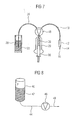
- FIG. 7 A schematic diagram showing a first known approach called the Syringe-Solenoid method is shown in Fig. 7.
- a fluid line 10 is fluidly connected via a high-speed microsolenoid valve 12 having a tip 14 which may be removable. At the lower end of the tip 14 is a nozzle opening 16.
- the opposite end of the fluid line 10 is connected via a switching valve 18 with a syringe pump 20.
- a fluid reservoir 22 is also connected to the switching valve 18 via a further fluid line 24.
- the switching valve 18 has two switching states. In a first switching state, a pump chamber 26 of the syringe pump 20 is fluidly connected via the fluid line 24 to the fluid reservoir 22, so that liquid 28 can be sucked from the fluid reservoir into the pumping chamber 26 by the volume of the pumping chamber 26 by a corresponding movement of the piston 30th the syringe pump is increased. This process is used to fill the syringe pump 20. In a subsequent metering operation, the switching valve 18 is switched to effect a fluid connection of the pumping chamber 26 via the fluid line 10 with the Mikrosolenoidventil 12.
- a pressure is exerted on the fluid in the pumping chamber 26, so that liquid can be discharged from the metering orifice 18 of the tip 14 by rapidly switching the microsolute valve 12 (switching time ⁇ 1 ms).
- Dosing devices of the type shown in Fig. 7 are sold for example by the company Cartesian.
- FIG. 8 An alternative principle, as practiced by, for example, Delo and Vermes, is shown in FIG.
- a pressure vessel 40 is provided in which a pressurized liquid 42 is located.
- An outlet of the pressure vessel 40 is connected via a fluid line 44 to a fast-switching valve 46, which in turn is connected via a fluid line 48 with a nozzle opening, which is shown in Fig. 8 only schematically as an arrow. Also at This arrangement can be discharged by rapidly switching the valve 46 liquid in the free jet from the nozzle opening.
- microdosing devices are described, for example, in DE-A-19802367, DE-A-19802368 and EP-A-0725267.
- the Mikrodosiervoriquesen described therein comprise a pumping chamber to which a flexible membrane is adjacent and which is connected via a feed line to a reservoir and via a discharge line with a nozzle opening.
- An example of such a microdosing device will be explained below with reference to Figs. 9a-9c.
- FIG. 9 a shows a schematic cross section through such a microdosing device in the idle state.
- the metering device comprises a metering head 50 and an actuator 52.
- the metering head 50 is formed by two interconnected substrates 54, 56 in which respective recesses are created.
- the first substrate 54 is structured such that a reservoir connection 58, an inlet channel 60 and a metering chamber 62 are formed therein.
- the lower substrate 56 is structured to have therein a nozzle connection 64, a nozzle 66 having a nozzle channel and an outlet opening, and an outlet portion 68 having a substantially larger cross-section than the outlet opening of the nozzle 66.
- a membrane 70 is further formed therein.
- the actuator 52 has a displacer 72 through which the diaphragm 70 can be deflected downwardly to reduce the volume of the metering chamber 62, as shown in Figure 9b. This reduction in the volume of the metering chamber 72 results in a return flow 74 through the inlet channel 60 and the reservoir connection 58.
- the displacer 72 is moved upwards using the actuator 52, see Fig. 9c, so that it finally resumes the original position as shown in Fig. 9a by its elasticity.
- This return of the membrane 70 results in an increase in the volume of the metering chamber 62, so that a refill flow 78 from the reservoir through the reservoir connection 58 and the inlet channel 60 takes place.
- the return of the membrane 70 must be slow enough that the same capillary forces holding liquid in the nozzle 66 will not overcome it.
- Microdosage devices as described above with respect to Figures 9a-9c were originally developed for enzyme dosage in biochemistry. Using these devices, liquids with viscosities up to 100 mPas in a volume range from 1 nL to 1000 nL can be metered very media-independent and precise.
- the liquid to be dispensed is metered by displacement from the metering chamber of a metering chip, preferably made of silicon, in the free jet.
- this method requires a comparatively complex microcomponent.
- US Pat. No. 3,683,212 discloses a droplet ejection system in which a tubular piezoelectric transducer has a fluid line with a nozzle plate in which a nozzle opening is formed, connects.
- a short rise time voltage pulse is applied to the transducer to cause contraction of the transducer.
- the resulting sudden decrease in trapped volume causes a small amount of fluid to be expelled from the orifice in the orifice plate.
- the liquid is kept under no or a low static pressure.
- the surface tension at the opening prevents liquid from flowing out when the transducer is not actuated.
- the ejected liquid is replaced by a capillary forward flow of liquid in the line.
- the droplet is generated by means of an acoustic principle similar to the piezoelectric ink-jet method.
- an acoustic pressure wave is generated in a rigid fluid conduit, for example a rigid glass capillary, which at the delivery location locally results in a high pressure gradient, which leads to droplet detachment.
- the actuation time of the actuator is here in the order of magnitude of the sound propagation in the system, which is usually a few microseconds. Therefore, in this context, the acoustic impedance of the fluid lines below and above the actuator for the interpretation of importance. It is therefore a pulse method in which a high acoustic impulse is generated at low volume displacement.
- a sound wave is generated with pressure maxima and pressure minima between the location of the actuation and the discharge point, wherein a discharge of liquid is effected by a corresponding pressure at the delivery point.
- the fluid line is deformed only negligibly, essentially only sound is transmitted by the actuator, and the elasticity of the fluid line does not play a decisive role.
- a device for dosing of liquids which comprises a liquid supply hose having one end connected to a liquid reservoir and the other end open.
- the hose abuts against a restocking base and a hammer is provided on the opposite side of the hose from the restocking base.
- the hammer is displaceable in periodic oscillations in the direction transverse to the tube axis, so that the entire tube cross-section is squeezed by the hammer, that is, the flow area is brought to substantially zero.
- impulsive force impulses are exerted on the tube and expelled individual drops of liquid from the open end.
- fluidic impedance is meant the combination of fluidic resistance and fluidic inductance determined by the length and flow area of a conduit.
- the present application thus makes it possible to adjust the metering volume by either adjusting the stroke of the actuating device and / or adjusting the position of the actuating device along a fluid line whose volume can be changed.
- Such variability of the ratio of said flow resistances may preferably be achieved by forming the fluid conduit between the liquid reservoir and the ejection port with a substantially linear configuration, i. H. between the liquid reservoir and ejection opening has a cross section without abrupt cross-sectional changes. In the simplest case, this can be achieved by the fluid line between the liquid reservoir and discharge opening in the idle state has a substantially constant cross-section.
- the present invention requires no fine mechanical or microstructured components, as they are necessary with other drop generators, whereby the manufacturing cost can be significantly reduced and the reliability is increased. Further, the fluid-carrying parts can be made as disposable components simply made of plastic, such as polyimide, thereby eliminating a costly cleaning when changing media.
- no limited pressure chamber is used to generate the pressure, but a variable "active area".
- a preferred direction of a fluid flow in the fluid conduit can be generated in the direction of the outlet opening.
- a simple change of the maximum metering volume can be brought about by enlarging the "active area", for example by using a larger displacer, wherein such a change of the maximum metering volume requires no structural changes to the fluid-carrying parts.
- the present invention thus provides additional degrees of freedom in setting a desired metering volume.
- a desired metering volume can be set by the above-mentioned steps. If the stroke and thus the displacement of the actuating device can be adjusted, a desired dosing volume range can be set by the above-mentioned steps, in which case the respective dosing volume lying in the desired dosing volume range can be set by adjusting the stroke or the displacement of the actuating device.
- a characteristic feature and a significant advantage of volume displacement systems, as realized by the present invention, is that in the same dosing volume is largely independent of the viscosity of the liquid to be dosed.
- the actuator may be designed together with the fluid conduit to allow complete squeezing of the fluid conduit through the displacer as an extreme case of volume displacement.
- a valve function can additionally be implemented. The possibility of a complete interruption of the fluid line between reservoir and discharge point can thus represent a further advantage over known methods.
- FIGS. 1a to 1c the essential features of the present invention as well as the concept underlying the same are explained below.
- the present invention relates to a device or a method for producing microdrops or microbeams, mainly in the nanoliter to picoliter range.
- the central element of a microdosing device according to the invention is a fluid-carrying line which has a flexible hose and whose inlet opening is connected to a liquid reservoir in which the medium to be dosed is located. At the other end of the line is an outlet opening through which the liquid to be dispensed can be dispensed.
- the fluid-carrying line is preferably made primarily of an elastic material, so that the volume of the conduit between inlet opening and outlet opening can be varied by deformation of the conduit, for example by compressing it.
- FIGS. 1a to 1c The essential elements of a metering device according to the invention during different phases of a metering operation are shown in FIGS. 1a to 1c.
- a fluid conduit 100 which in preferred embodiments of the present invention is an elastic polymer tube, includes an inlet end 102 for connection to a fluid reservoir and an outlet end 104 at which Microdrops or micro-jets can be dispensed.
- the outlet end 104 can thus also be referred to as a nozzle.
- Respective walls 106 of the elastic polymer tube 100 are shown in dashed lines in FIGS. 1a to 1c.
- An actuator 108 in the form of a displacer which has a connection part 110 to which the displacer 108 can be attached to an actuator for driving the displacer 108.
- the elastic polymer tube has a substantially constant cross-section from its inlet end 102 to its outlet end 104, which will generally be circular.
- a region 112 disposed below the displacer 108 may be referred to as a dosing chamber region defined by the position of the displacer 108 with respect to the elastic polymer tube 100.
- a portion 114 that begins substantially at the right end of the displacer 108 represents an exhaust passage that fluidly connects the displacer portion 112 to the outlet end 104.
- the displacer 108 may include a displacer surface 120 extending obliquely to the wall 106 of the polymer tubing 100, allowing for the production of a preferential direction of fluid flow towards the outlet port 104 by axial asymmetric volume change during operation of the microdispenser.
- the fluid line 100 is filled either by itself via an externally generated pressure difference or by capillary forces.
- An externally generated pressure difference may be applied, for example, by using a liquid reservoir by pressurizing the liquid.
- a negative pressure (negative pressure) relative to the outlet end may be applied to prevent leakage of liquid from the outlet end in the non-actuated state if the capillary forces are too weak for this. This counteracting pressure must be overcome when filling by the capillary forces.
- a first phase which may be termed a metering phase
- liquid is displaced from the conduit by a reduction in the line volume between the inlet port and the outlet port. This is achieved by placing the displacer 108 down, i. H. is moved toward the polymer tube 100, so that a compression of the polymer tube takes place in the displacement 112. This downward movement is illustrated by arrows 122 in FIG. 1b.
- the displacer region 112 thus represents the active region of the microdosing device according to the invention.
- the fluid displaced from the conduit due to this change in volume of the fluid conduit 100 becomes the ends the line out or stored by a change in the line cross-section elsewhere, if the line has a fluidic capacity.
- the fluidic resistances between outlet opening 104 and active area 112, in which the volume change occurs ie the fluidic impedance of outlet channel 114
- the fluidic impedance of the line section between active area 14 and inlet opening 112 ie, the fluidic impedance of inlet channel 116)
- Good dosing quality can be achieved, for example, if the volume change in the vicinity of the outlet opening 104 is performed with a high dynamic range (for example 50 nL within one millisecond).
- the fluidic impedance of the outlet channel 114 may be made small compared to the fluidic impedance of the inlet channel 116, so that a large part of the displaced liquid is expelled from the outlet opening 104.
- the displacer is arranged in the vicinity of the outlet opening 104, if the length of the inlet channel 116 is at least twice as long as the length of the outlet channel 114, more preferably at least five times as large and even more preferably at least ten times as large ,
- the volume between inlet opening 102 and outlet opening 104 is increased again in a second phase, which can be referred to as refill phase.
- This is achieved by moving the displacer 108 away from the fluid conduit 100 in the direction of an arrow 132, as shown in Fig. 1c. Due to this change in volume, liquid from the reservoir flows through the inlet port 102 and the inlet channel 116 into the conduit, and more particularly into the active area 112 thereof, as indicated by an arrow 134 in FIG. 1c.
- the suction of air through the outlet opening 104 is prevented at correspondingly small line cross-sections by capillary forces.
- a preferred direction for filling from the reservoir can be predetermined by a hydrostatic pressure difference between inlet opening and outlet opening. For this purpose, for example, in turn, the liquid reservoir could be subjected to a pressure.
- FIGS. 2a to 2d show a drop generator using a microdosing device according to the invention with corresponding holders for the fluid line or the actuating device.
- Fig. 2a shows a side view of the drop generator
- Fig. 2b is a bottom view thereof.
- Fig. 2c is a sectional view taken along the line A-A of Fig. 2b
- Fig. 2d shows an enlargement of the section B in the scale 5: 1.
- the drop generator shown in FIGS. 2 a to 2 d comprises a polyimide tube 150, which may have, for example, an inner diameter of 200 ⁇ m.
- a bearing block 152 and an abutment block 154 are provided for storage of the polyimide tube 150.
- a guide groove is provided in the bearing block 152 and / or the abutment block 154, in which the polyimide hose is inserted, so that the polyimide hose between bearing block and abutment block is securely mounted in a stabilized manner.
- the bearing block 152 and the abutment block 154 are attached to a holding portion 160 of a holder 162 using, for example, retaining screws 156.
- the holder 162 is further formed to hold on the opposite side of the abutment 154 of the polyimide tube 150 a displacer 164, with the aid of the tube in the active region thereof can be compressed, whereby the volume change of the invention between the inlet opening and outlet opening is achieved.
- the displacer is thereby driven by a piezo stack actuator (not shown), the deflection of which can be electronically controlled, and which is connected via an adapter 166 to the displacer 164.
- the displacer 164 again has a relative beveled to the polyimide hose, that is, at an angle, displacement surface.
- the holder 162 further comprises a receptacle 170 for the drive unit in the form of Piezostackackaktuators. Furthermore, the holder 162 may have a recess 172 penetrating the same in order to enable it to be attached to a device which also contains the drive unit, for example by using a screw connection.
- FIG. 3 shows different phases of a dosing operation carried out by means of the prototype, wherein in each case the polyimide tube 150 is shown with its outlet end 180.
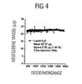
- Fig. 4 shows the delivered mass in micrograms at a number of 1800 dosing operations using the prototype, using water as the liquid to be dosed.
- the average drop mass was 22.57 ⁇ g, with a standard deviation ⁇ of 0.35 ⁇ g.
- the polyimide tube had a diameter of 200 ⁇ m.
- the gravimetric measurement of the reproducibility shown in FIG. 4 proves that with the concept according to the invention a precision can be achieved which at least corresponds to that of conventional metering devices and is even superior to it.
- a desired metering volume or a desired metering volume range can be set in a microdosing device according to the invention.
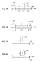
- FIGS. 5a and 5b Shown schematically in FIGS. 5a and 5b is the polymer tube 100, whose inlet opening 102 is fluidically connected to a liquid reservoir 200, and whose outlet end 104 constitutes an ejection opening.
- the active area 112 as well as the outlet channel 114 and the inlet channel 116 are defined by the position of the displacer 108.
- the inlet channel 116 and the outlet channel 114 have substantially equal lengths x 1 and x 2 , so that the fluidic impedance thereof is substantially identical assuming a constant cross section of the tube 100.
- volume displacement caused by the displacer 108' would result in flows of equal size flowing toward the outlet port 104 and the inlet port 102.
- the volume expelled through the outlet port 104 would be half the volume displacement caused by the displacer 108 '.
- the displacer 108 ' is arranged in the vicinity of the outlet opening 104.
- the length x 1 of the intake passage 116 is about five times as large as the length of the exhaust passage x 2 .
- the fluidic impedance of the inlet channel 116 at constant cross-section of the tube 100 is five times that of the outlet channel 114, so that a much greater proportion of the volume change effected by the displacer 108 'will flow toward the outlet port 104 and thus expel through it causes.
- the above adjustment of the position may be adjustment represent a desired Dosiervolumen Scheme, while the final setting the desired dosing volume is carried out in the set dosing volume range by a corresponding control of the displacer.
- the dosing volume delivered at the outlet opening can be adjusted by changing the position of the displacer, as long as the ratio of the flow resistances of the inlet channel and outlet channel can be changed appreciably by changing the position of the displacer.
- a change is here to be understood which results in a change of a dispensing volume dispensed at the outlet opening by at least 10%, wherein the actual setting range will depend on the range over which the position of the displacer can be adjusted. It can be realized by changing the position of the displacer using the microdosing devices according to the invention also changes the dispensed dosing volume by 50% and above.
- This adjustability according to the invention of the ratio of the flow resistances of the inlet channel and the outlet channel is preferably possible according to the invention in that between metering chamber, i. H. active region, and inlet channel or outlet channel no sudden cross-sectional changes take place.
- the cross-section of the fluid conduit is from the segment of the displacement, i. H. the active area, to the outlet opening at rest constant.
- the entire fluid line between the liquid reservoir and the outlet has a substantially constant cross-section.
- FIGS. 6a and 6b A second possibility, as according to the invention a desired metering volume or a desired metering volume range can be adjusted, can be seen in FIGS. 6a and 6b.
- the displacer 108 ' has a length l 1 along the tube 100
- a displacer 208 has a length l 2 along the tube 100.
- the length l 2 is greater than the length l 1 , so that the displacer 208 allows a larger volume change of the fluid line 100 at the same stroke.
- a desired metering volume or, similarly to the above explanations a desired metering volume range can be set.
- the present invention thus provides a microdosing device which has a fluid line filled with a medium to be metered, one end of which is connectable to a fluid reservoir and at the other end of which is an outlet opening, and an actuating device, by which the volume of a certain segment of the fluid line can be changed over time, so that is given off by the volume change liquid as free-flying droplets or as a free-flying beam at the outlet.
- the entire fluid line can be formed by a flexible polymer tube.
- only the particular segment addressed can be formed by a flexible polymer tube, while the inlet and outlet of this segment are formed by a rigid fluid line.
- the displacement takes place on an elastic segment of the fluid conduit.
- the elastic segment in the fluid line for example the flexible polymer tube or the membrane, after an operation by itself again assume the initial state, so that the displacer does not have to be firmly connected to the fluid line, so that the fluid line be designed as a simple disposable component can.
- the present invention also includes drop generators in which a plurality of microdosing devices according to the invention are arranged in parallel. Such parallel arranged microdosing can be controlled separately to dose different liquids or the same liquids.
- a drop generator may have a plurality of fluid lines, which are simultaneously controlled by a displacer, so that the same or different liquids can be metered by the same.
- the inlet ends of the different fluid lines may be connected to the same or different liquid reservoirs.
- a microdosing device can thus consist of one or more microdroplet generators each having an (elastic) fluidic line filled with a medium to be dosed, one end of which has an inlet opening connected to a liquid reservoir, and an outlet opening at the other end thereof wherein there may be a pressure difference between the inlet opening and the outlet opening and an actuating means by which the volume of the conduit between the liquid reservoir and the outlet opening can be changed over time, in a first phase the fluid volume between inlet opening and outlet opening having sufficient speed from its initial volume a smaller volume is reduced, thereby a microdrop is ejected through the outlet port and a portion of the displaced volume is allowed to escape to the inlet port, wherein the volume of microbubble plus the volume receding into the reservoir through the inlet port is substantially equal to the volumetric change brought about by the actuator; second phase, in which the volume between the inlet opening and outlet opening is increased again, whereby the fluidic line driven by pressure or capillary forces filled out of the reservoir again.
- an automated holder can also be provided, which enables an automatic adjustment of the position of the displacer to the fluid line, for example in response to a signal indicating a desired metering volume range or a desired metering volume.
- individual free-floating microdroplets are preferably created at an exit port in contact with the surrounding atmosphere to thereby dispense liquid as free-flying droplets or free-flowing jet at the exit port.
- the present invention enables the ejection of a droplet already in a single actuation cycle of the actuator, during which the displacer once causes a reduction in the volume of the fluid line, thereby expelling the droplet.
- the present invention allows adjustment of the dosing volume by adjusting the stroke of the moving means and / or arranging the actuating means at a predetermined position along the portion of a fluid conduit.
- a displacer with a matched axial length can be selected.
- the stroke h of the actuator or displacer is variable and less than the diameter of the tube, i. the cross-sectional dimension thereof in the direction of movement of the displacer of the actuator.
- the drop volume is determined by the extent of the hammer along the tube axis and by the tube diameter.
- the entire volume located in the relevant tube section is displaced.
- V a 4 ⁇ ⁇ ⁇ d 2
- V is the displaced volume
- a is the length of the displacer
- d is the diameter of the tube.
- H represents the distance around which the hose is compressed.
- the present invention enables a variable adjustment of the dosing volume without having to connect a hose with a different diameter or a displacer with different dimensions.
- the present invention also allows dosing at a non-periodic excitation. This is advantageous, inter alia, when targeted non-periodic patterns are to be printed on a substrate.
- the actuator is each designed to effect actuation of the hose from an uncompressed state thereof.
- the hose is partially or completely squeezed off in standby mode, i. is compressed.
- a schematic cross-sectional view of such an embodiment is shown in Fig. 10a.
- the hose 100 rests with its back against a counter-holding element 300.
- a piezoactuator 302 is attached to a holder 304 of an actuator.
- a displacer 306 is arranged at the front end of the piezoelectric actuator 302, a displacer 306 is arranged.
- the tube 100 is completely squeezed off in standby mode.
- the dosing cycle starts with a slow retraction of the piezoactuator 302, so that the cross section of the hose 100 is partially released.
- liquid from the reservoir to which the tube 100 is connected at the end 102 opposite the outlet opening 104 flows into the previously squeezed area around which compensate for increasing tube volume.
- the actual dosing process with the droplet formation at the outlet end 104 then takes place with the rapid extension of the piezoactuator 302 in order to reduce the tube volume again.
- the metered volume is defined as in the embodiments described above by the travel of the piezoelectric actuator 302 and can thus be controlled by varying the operating voltage or via the variation of the charging or discharging the piezoelectric actuator 302.
- An advantage of the configuration shown in FIG. 10a is that the clamped hose has a significantly lower rate of evaporation of the medium to be metered than the hose which is normally open.
- the embodiment thus includes an integrated locking mechanism.
- the extended state of the piezo actuator is the state in which the electrical voltage is applied.
- the embodiment of an integrated shutter mechanism shown in FIG. 10a entails continuous, albeit small, energy consumption.
- An integrated shutter mechanism with reduced power consumption is implementable by providing the actuator with biasing means, such as a spring, which presses the displacer against the polymer tubing to achieve partial or total hose pinch off in standby mode.
- the actuator then preferably has an actuator which is arranged to the displacer to move against the force of the biasing device and partially or completely release the tube cross-section.
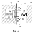
- FIG. 10b An exemplary embodiment of such an integrated closure mechanism is shown in FIG. 10b.
- the hose 100 in turn abuts against a counter-holding device 310.
- An actuator in this embodiment comprises a combination of a spring 312 and a piezostack actuator 314.
- the actuator further includes a displacer 316 that is rigidly coupled to an actuator plate 318.
- two coupling rods 320 and 322 are shown in FIG. 10b.
- the spring 312 abuts a counter-holding element 324 at its right-hand end and, in the non-actuated state of the actuator 314, presses the displacer 316 against the hose 100 in order to squeeze it.
- This embodiment makes it possible to realize a metering device whose hose is squeezed when the electrical supply voltage is switched off, so that it has an integrated shutter mechanism without continuous energy consumption.
- the displacer 316 is pressed onto the tube 100 by the spring so that it is pressed against the counter-support 310 and squeezed off. If a dosing process takes place, the piezoelectric actuator 314 is extended by applying an electrical voltage and thus the displacer 316 is reset against the spring force. The tube relaxes and the liquid to be dispensed flows from the reservoir which is connected to the side 102 of the tube opposite the outlet opening 104. Rapid retraction of the piezo stack actuator 318 causes the tube 100 to be squeezed again via the spring 312, which is dimensioned sufficiently strongly for this purpose.
- the spring is rigid enough dimensioned so that liquid is metered out as a free-flowing jet from the discharge opening 104.
- the dosed volume is in turn defined by the travel of the piezoelectric actuator and can thus be controlled by varying the operating voltage or via the variation of the charging or discharging the piezo stack actuator.
- the displacer is moved between a first end position and a second end position, wherein the polymer tube is partially compressed in the first end position or the second end position is.
- the first end position defines a larger tube volume than the second end position, so that liquid is metered out of the ejection end by moving the displacer from the first end position to the second end position.
- the first end position can then define a completely relaxed state of the hose or a partially compressed state of the same.
- the second end position may include a partially compressed state or a fully compressed state of the polymer tube.
- the tube wall is moved by the actuating device or the displacer over part of the clear cross section of the flexible polymer tube.
- the tube wall is moved over the entire clear cross-section of the tube.
- FIGS. 10a and 10b can also be implemented in such a way that the position of the actuating device can be varied in order thereby to be able to vary the dosing volume dispensed from the outlet opening.
Landscapes
- Health & Medical Sciences (AREA)
- Clinical Laboratory Science (AREA)
- Chemical & Material Sciences (AREA)
- Chemical Kinetics & Catalysis (AREA)
- Feeding, Discharge, Calcimining, Fusing, And Gas-Generation Devices (AREA)
- Automatic Analysis And Handling Materials Therefor (AREA)
- Measuring Volume Flow (AREA)
- Infusion, Injection, And Reservoir Apparatuses (AREA)
- Physical Or Chemical Processes And Apparatus (AREA)
Claims (30)
- Dispositif de microdosage aux caractéristiques suivantes :un conduit à fluide (100 ; 150) présentant un flexible souple, avec une première extrémité (102) pour le raccordement à un réservoir à fluide (200), et une deuxième extrémité à laquelle se trouve une ouverture de sortie (104) ; etun dispositif d'actionnement présentant un organe de refoulement (108 ; 108' ; 208 ; 306 ; 316) à course réglable par lequel peut être modifié le volume d'un segment du flexible souple, pour délivrer ainsi, par déplacement de l'organe de refoulement (108 ; 108' ; 208 ; 306 ; 316) entre une première position de fin de course et une deuxième position de fin de course, du liquide sous forme de gouttes libres ou de jet libre à l'ouverture de sortie (104), le flexible étant partiellement comprimé au moins dans la première position de fin de course ou la deuxième position de fin de course.
- Dispositif de microdosage selon la revendication 1, dans lequel le flexible souple est réalisé en polyimide.
- Dispositif de microdosage selon la revendication 1 ou 2, dans lequel le flexible souple présente au moins un segment dans lequel il ne présente pas de variations de section brusques, de sorte que par la modification de la position du dispositif d'actionnement (108 ; 108' ; 164 ; 208) le long du segment peut être varié un rapport entre une impédance fluidique entre la position du dispositif d'actionnement et l'ouverture de sortie (104) et une impédance fluidique entre la première extrémité (102) et la position du dispositif d'actionnement, de sorte qu'un volume de dosage délivré à l'ouverture de sortie (104) puisse être varié d'au moins 10%.
- Dispositif de microdosage selon l'une des revendications 1 à 3, dans lequel le flexible peut être comprimé sur une longueur prédéterminée par l'organe de refoulement (108 ; 108' ; 208 ; 306 ; 316), pour provoquer la variation de volume du flexible.
- Dispositif de microdosage selon la revendication 4, dans lequel l'organe de refoulement (108) présente une forme pour provoquer une variation de volume axialement asymétrique par rapport au flexible.
- Dispositif de microdosage selon l'une des revendications 1 à 5, présentant, par ailleurs, un dispositif (150, 152, 162) destiné à maintenir le dispositif d'actionnement en une ou la position le long du flexible.
- Dispositif de microdosage selon l'une des revendications 1 à 6, présentant un dispositif de prétension (312), pour prétendre le flexible par l'organe de refoulement (316) à un état entièrement ou partiellement comprimé.
- Dispositif de microdosage selon la revendication 7, dans lequel le dispositif d'actionnement présente un actionneur (314, 320, 322) qui est disposé de manière à déplacer l'organe de refoulement (316) à l'encontre de la prétension du dispositif de prétension (312).
- Dispositif de microdosage aux caractéristiques suivantes :un conduit à fluide (100 ; 150) avec une première extrémité (102) pour le raccordement à un réservoir à fluide (200) et une deuxième extrémité à laquelle se trouve une ouverture de sortie (104),le conduit à fluide (100 ; 150) présentant un segment souple le long duquel peut être variée une section du conduit à fluide, pour provoquer une variation du volume du conduit à fluide ;un dispositif d'actionnement (108 ; 108' ; 164 ; 208), qui est disposé en une position le long du segment du conduit à fluide, pour provoquer une variation du volume du conduit à fluide, pour délivrer ainsi le liquide sous forme de gouttes libres ou de jet libre de l'ouverture de sortie (104),un rapport entre une impédance fluidique entre la position du dispositif d'actionnement (108 ; 108' ; 164 ; 208) et l'ouverture de sortie (104) et une impédance fluidique entre la première extrémité (102) et le conduit à fluide (100 ; 150) et la position du dispositif d'actionnement pouvant être varié en variant la position du dispositif d'actionnement, de sorte qu'un volume de dosage délivré à l'ouverture de sortie (104) puisse être varié d'au moins 10%.
- Dispositif de microdosage selon la revendication 9, dans lequel le dispositif d'actionnement présente un organe de refoulement (108 ; 108' ; 164 ; 208) par lequel le segment du conduit à fluide (100 ; 150) peut être comprimé sur une longueur prédéterminée, pour provoquer la variation de volume du segment du conduit à fluide.
- Dispositif de microdosage selon la revendication 10, dans lequel l'organe de refoulement (108) présente une forme pour provoquer une variation de volume axialement asymétrique par rapport au segment du conduit à fluide (100 ; 150).
- Dispositif de microdosage selon l'une des revendications 9 à 11, présentant, par ailleurs, un dispositif (150, 152, 162) destiné à maintenir le dispositif d'actionnement à la position le long du segment du conduit à fluide.
- Dispositif de microdosage selon l'une des revendications 9 à 12, dans lequel le conduit à fluide (100 ; 150) ne présente, à l'état de repos, pas de variations de section brusques entre la première extrémité (102) et l'ouverture de sortie (104).
- Dispositif de microdosage selon l'une des revendications 1 à 12, dans lequel le conduit à fluide (100 ; 150) présente, à l'état de repos, une section sensiblement constante entre la première extrémité (102) et l'ouverture de sortie (104).
- Dispositif de microdosage selon l'une des revendications 1 à 14, présentant, par ailleurs, un dispositif destiné à soumettre le conduit à fluide à une différence de pression.
- Dispositif de microdosage selon l'une des revendications 1 à 15, dans lequel le conduit à fluide (100 ; 150) présente une surface de section telle qu'un liquide à doser peut être déplacé à travers ce dernier par des forces capillaires.
- Dispositif de microdosage selon l'une des revendications 1 à 16, présentant une pluralité de conduits à fluide respectifs, de sorte que puissent être délivrés, simultanément ou successivement, plusieurs liquides identiques ou différents.
- Dispositif de microdosage selon la revendication 17, présentant un dispositif d'actionnement destiné à provoquer simultanément la variation de volume de la pluralité de conduits à fluide.
- Dispositif de microdosage selon la revendication 18, dans lequel le dispositif d'actionnement est un organe de refoulement commun.
- Procédé pour délivrer des liquides de manière dosée, aux étapes suivantes consistant à :remplir un conduit à fluide (100 ; 150) présentant un flexible souple avec un liquide à doser ;provoquer une variation de volume d'un segment du flexible souple par un organe de refoulement (108 ; 108' ; 208 ; 306 ; 316) à course réglable, pour délivrer ainsi, par le déplacement de l'organe de refoulement (108 ; 108' ; 208 ; 306 ; 316) entre une première position de fin de course et une deuxième position de fin de course, du liquide comme gouttes libres ou comme jet libre à une ouverture de sortie (104) du conduit à fluide (100 ; 150), le flexible étant partiellement comprimé au moins dans la première position de fin de course ou la deuxième position de fin de course.
- Procédé selon la revendication 20, présentant, par ailleurs, l'étape consistant à mettre à disposition un organe de refoulement (108; 108' ; 164; 208) à une position le long du flexible par lequel le flexible peut être comprimé sur une longueur prédéterminée, pour provoquer une variation de volume du segment de ce dernier.
- Procédé selon la revendication 21, dans lequel le conduit à fluide (100 ; 150) présente une première extrémité (102) connectée à un réservoir à fluide (200) et une deuxième extrémité à laquelle se situe l'ouverture de sortie (104), présentant, par ailleurs, l'étape suivante consistant à :sélectionner la position de l'organe de refoulement le long du flexible, pour régler un rapport entre l'impédance fluidique entre la position de l'organe de refoulement (108 ; 108' ; 164 ; 208) et l'ouverture de sortie (104) et une impédance fluidique entre la première extrémité (102) et la position du dispositif d'actionnement, pour délivrer ainsi, en provoquant la variation de volume, un volume de dosage souhaité à l'ouverture de sortie (104).
- Procédé selon la revendication 21 ou 22, présentant, par ailleurs, une étape consistant à sélectionner un organe de refoulement (108 ; 108' ; 164 ; 208) avec une longueur axiale par rapport au flexible souple, pour provoquer la variation de volume à l'aide de l'organe de refoulement et délivrer un volume de dosage souhaité à l'ouverture de sortie (104).
- Procédé selon l'une des revendications 20 à 23, dans lequel est réalisée, à l'étape consistant à provoquer la variation de volume, une variation de volume axialement asymétrique par rapport au flexible souple, pour provoquer dans le conduit à fluide (100 ; 150) un flux de liquide avec une direction préférée vers l'ouverture de sortie (104).
- Procédé selon l'une des revendications 20 à 24, présentant, par ailleurs, une étape de soumission du conduit à fluide (100 ; 150) à une pression statique.
- Procédé selon la revendication 25, dans lequel la pression statique est, en ce qui concerne l'extrémité de sortie, une surpression, pour provoquer, lors de la provocation de la variation de volume dans le conduit à fluide (100 ; 150), un flux de liquide avec une direction préférée vers l'ouverture de sortie (104) et/ou pour assister un nouveau remplissage après une opération de dosage.
- Procédé selon la revendication 25, dans lequel la pression statique est, par rapport à l'extrémité de sortie, une dépression, pour éviter une sortie de liquide à l'extrémité de sortie lorsqu'il n'est pas provoqué de variation de volume.
- Procédé selon l'une des revendications 20 à 27, présentant, par ailleurs, après l'étape consistant à provoquer une variation de volume, une étape consistant à annuler la variation de volume, de sorte que le flexible retourne à l'état de départ, pendant cette étape ayant lieu un nouveau remplissage capillaire du conduit à fluide (100 ; 150).
- Procédé pour régler un volume de dosage souhaité dans une opération de dosage à l'aide d'un dispositif de microdosage selon la revendication 9, avec l'étape suivante consistant à :disposer le dispositif d'actionnement (108 ; 108' ; 164) en une position prédéterminée le long du segment du conduit à fluide (100 ; 150), de sorte qu'il puisse, par suite du rapport en résultant entre les impédances fluidiques dans une étape consistant à provoquer une variation du volume du conduit à fluide (100 ; 150), être délivré un volume de dosage souhaité à l'ouverture de sortie (104).
- Procédé pour régler un volume de dosage souhaité dans une opération de dosage à l'aide d'un dispositif de microdosage selon la revendication 10, avec l'étape suivante consistant à :sélectionner un organe de refoulement (108 ; 108' ; 164 ; 208) avec une longueur axiale (I1, I2) par rapport au segment du conduit à fluide (100 ; 150) qui est adaptée de manière à permettre, dans une étape consistant à provoquer une variation du volume du conduit à fluide (100 ; 150), la délivrance d'un volume de dosage souhaité à l'ouverture de sortie ( 104).
Applications Claiming Priority (2)
| Application Number | Priority Date | Filing Date | Title |
|---|---|---|---|
| DE10337484A DE10337484B4 (de) | 2003-08-14 | 2003-08-14 | Mikrodosiervorrichtung und Verfahren zur dosierten Abgabe von Flüssigkeiten |
| PCT/EP2004/009063 WO2005016534A1 (fr) | 2003-08-14 | 2004-08-12 | Dispositif de microdosage et procede de delivrance dosee de liquides |
Publications (2)
| Publication Number | Publication Date |
|---|---|
| EP1654068A1 EP1654068A1 (fr) | 2006-05-10 |
| EP1654068B1 true EP1654068B1 (fr) | 2007-01-24 |
Family
ID=34177580
Family Applications (1)
| Application Number | Title | Priority Date | Filing Date |
|---|---|---|---|
| EP04764062A Expired - Lifetime EP1654068B1 (fr) | 2003-08-14 | 2004-08-12 | Dispositif de microdosage et procede de delivrance dosee de liquides |
Country Status (7)
| Country | Link |
|---|---|
| US (1) | US7900850B2 (fr) |
| EP (1) | EP1654068B1 (fr) |
| JP (1) | JP2007502399A (fr) |
| CN (1) | CN100428998C (fr) |
| AT (1) | ATE352374T1 (fr) |
| DE (2) | DE10337484B4 (fr) |
| WO (1) | WO2005016534A1 (fr) |
Cited By (2)
| Publication number | Priority date | Publication date | Assignee | Title |
|---|---|---|---|---|
| EP3450020A1 (fr) | 2017-09-01 | 2019-03-06 | Eppendorf AG | Dispositif de microdosage permettant le dosage de plus petits échantillons de fluide |
| EP3485974A1 (fr) | 2017-11-17 | 2019-05-22 | Eppendorf AG | Dispositif de microdosage permettant le dosage de plus petits échantillons de fluide |
Families Citing this family (90)
| Publication number | Priority date | Publication date | Assignee | Title |
|---|---|---|---|---|
| GB0607427D0 (en) * | 2006-04-13 | 2006-05-24 | Imi Vision Ltd | Fluid dispenser |
| DE102006047579A1 (de) * | 2006-10-05 | 2008-04-17 | Institut Für Solarenergieforschung Gmbh | Verfahren zur Herstellung von Solarzellen mit durch eine Ätzlösung lokal strukturierten Oberflächen |
| ITVR20070024A1 (it) * | 2007-02-15 | 2008-08-16 | Z G Camini Inox S R L | Dispositivo di pompaggio particolarmente per fluidi contenenti sospensioni solide |
| US8479784B2 (en) * | 2007-03-15 | 2013-07-09 | The Coca-Cola Company | Multiple stream filling system |
| US9394153B2 (en) | 2007-03-15 | 2016-07-19 | The Coca-Cola Company | Multiple stream filling system |
| US8387599B2 (en) | 2008-01-07 | 2013-03-05 | Mcalister Technologies, Llc | Methods and systems for reducing the formation of oxides of nitrogen during combustion in engines |
| US7628137B1 (en) * | 2008-01-07 | 2009-12-08 | Mcalister Roy E | Multifuel storage, metering and ignition system |
| US8635985B2 (en) | 2008-01-07 | 2014-01-28 | Mcalister Technologies, Llc | Integrated fuel injectors and igniters and associated methods of use and manufacture |
| US8986253B2 (en) | 2008-01-25 | 2015-03-24 | Tandem Diabetes Care, Inc. | Two chamber pumps and related methods |
| WO2009100123A2 (fr) | 2008-02-04 | 2009-08-13 | The Coca-Cola Company | Procédés de création de produits de boisson personnalisés |
| DE102008032328A1 (de) | 2008-07-09 | 2010-01-14 | Schaeffler Kg | Wälzlager mit einem Schmierungssystem |
| AU2010217760B2 (en) * | 2009-02-27 | 2015-04-09 | Tandem Diabetes Care, Inc. | Methods and devices for determination of flow reservoir volume |
| US9250106B2 (en) | 2009-02-27 | 2016-02-02 | Tandem Diabetes Care, Inc. | Methods and devices for determination of flow reservoir volume |
| DE202009014944U1 (de) * | 2009-03-26 | 2010-10-21 | Helmholtz-Zentrum Für Umweltforschung Gmbh - Ufz | Dosiervorrichtung für Bioreaktoren |
| EP3284494A1 (fr) | 2009-07-30 | 2018-02-21 | Tandem Diabetes Care, Inc. | Système de pompe à perfusion portable |
| US9109423B2 (en) * | 2009-08-18 | 2015-08-18 | Halliburton Energy Services, Inc. | Apparatus for autonomous downhole fluid selection with pathway dependent resistance system |
| KR101364416B1 (ko) | 2009-12-07 | 2014-02-17 | 맥알리스터 테크놀로지즈 엘엘씨 | 대형 엔진 적용에 적합한 일체식 연료 인젝터 점화기 및 연관된 이용 및 제조방법 |
| US8757511B2 (en) | 2010-01-11 | 2014-06-24 | AdvanJet | Viscous non-contact jetting method and apparatus |
| WO2011100701A2 (fr) | 2010-02-13 | 2011-08-18 | Mcalister Roy E | Ensembles injecteurs de combustible comprenant des modificateurs de force acoustique, et procédés d'utilisation et de fabrication associés |
| DE102010017216A1 (de) | 2010-06-02 | 2011-12-08 | Technische Universität Berlin | Ventilvorrichtung zum Steuern eines Flusses eines Fluides durch einen Fluidkanal, Anordnung sowie Mehrwegventilvorrichtung |
| ES2424216T3 (es) | 2010-06-02 | 2013-09-30 | Technische Universität Berlin | Dispositivo de válvula para controlar un flujo de un fluido a través de un canal de fluido, disposición así como dispositivo de múltiples vías |
| US20130153738A1 (en) | 2010-07-02 | 2013-06-20 | Mark J. Meiners | Anti-spin mounting pole and method of forming |
| USD673536S1 (en) * | 2010-07-02 | 2013-01-01 | Tubular USA, Inc. | Satellite mounting pole |
| US10154923B2 (en) | 2010-07-15 | 2018-12-18 | Eyenovia, Inc. | Drop generating device |
| FR2963872B1 (fr) * | 2010-08-18 | 2012-08-03 | Exel Ind | Dispositif et procede pour distribuer un produit liquide a projeter sur une surface |
| EP2665557B1 (fr) | 2011-01-21 | 2020-01-01 | Biodot, Inc. | Distributeur piézoélectrique à capteur longitudinal et tube capillaire remplaçable |
| US8919377B2 (en) | 2011-08-12 | 2014-12-30 | Mcalister Technologies, Llc | Acoustically actuated flow valve assembly including a plurality of reed valves |
| US9346075B2 (en) | 2011-08-26 | 2016-05-24 | Nordson Corporation | Modular jetting devices |
| US9254642B2 (en) | 2012-01-19 | 2016-02-09 | AdvanJet | Control method and apparatus for dispensing high-quality drops of high-viscosity material |
| EP2662137A1 (fr) | 2012-05-08 | 2013-11-13 | Roche Diagniostics GmbH | Ensemble de distribution |
| EP2662138A1 (fr) | 2012-05-08 | 2013-11-13 | Roche Diagniostics GmbH | Distributeur de microfluidique, cartouche et système d'analyse pour analyser un échantillon biologique |
| US9180242B2 (en) | 2012-05-17 | 2015-11-10 | Tandem Diabetes Care, Inc. | Methods and devices for multiple fluid transfer |
| DE102012209314B4 (de) | 2012-06-01 | 2015-04-02 | Albert-Ludwigs-Universität Freiburg | Vorrichtung und Verfahren zur Abgabe oder Aufnahme eines Flüssigkeitsvolumens |
| US9555186B2 (en) | 2012-06-05 | 2017-01-31 | Tandem Diabetes Care, Inc. | Infusion pump system with disposable cartridge having pressure venting and pressure feedback |
| GB201217390D0 (en) * | 2012-09-28 | 2012-11-14 | Agplus Diagnostics Ltd | Test device and sample carrier |
| US9169814B2 (en) | 2012-11-02 | 2015-10-27 | Mcalister Technologies, Llc | Systems, methods, and devices with enhanced lorentz thrust |
| US8746197B2 (en) | 2012-11-02 | 2014-06-10 | Mcalister Technologies, Llc | Fuel injection systems with enhanced corona burst |
| US9169821B2 (en) | 2012-11-02 | 2015-10-27 | Mcalister Technologies, Llc | Fuel injection systems with enhanced corona burst |
| CN105007963A (zh) | 2012-11-05 | 2015-10-28 | 阿克伦奥斯丁生物创新协会 | 低容量注射器吸量管 |
| US9200561B2 (en) | 2012-11-12 | 2015-12-01 | Mcalister Technologies, Llc | Chemical fuel conditioning and activation |
| US9173998B2 (en) | 2013-03-14 | 2015-11-03 | Tandem Diabetes Care, Inc. | System and method for detecting occlusions in an infusion pump |
| US9194337B2 (en) | 2013-03-14 | 2015-11-24 | Advanced Green Innovations, LLC | High pressure direct injected gaseous fuel system and retrofit kit incorporating the same |
| DE202013003390U1 (de) * | 2013-04-11 | 2014-07-14 | Brand Gmbh + Co Kg | Pipettiervorrichtung mit einer Mikrodosiereinheit |
| DE102013006227A1 (de) | 2013-04-11 | 2014-10-16 | Brand Gmbh + Co Kg | Pipettiervorrichtung mit einer Mikrodosiereinheit |
| EP3030352B1 (fr) | 2013-08-07 | 2019-03-20 | Roche Diagnostics GmbH | Cartouche pour distribuer un fluide, analyseur automatique et procédé d'analyse d'un échantillon biologique |
| US10076750B2 (en) | 2014-02-04 | 2018-09-18 | Austen Bioinnovation Institute In Akron | Plunger for low-volume syringe pipette |
| JP5802347B1 (ja) * | 2014-05-20 | 2015-10-28 | エンジニアリングシステム株式会社 | 微量液体滴下方法および微量液体ディスペンサ |
| WO2015178239A1 (fr) * | 2014-05-20 | 2015-11-26 | エンジニアリングシステム株式会社 | Procédé de distribution de liquide en microvolume et distributeur de liquide en microvolume |
| KR20170063514A (ko) * | 2014-07-25 | 2017-06-08 | 에프. 호프만-라 로슈 아게 | 1밀리미터 미만의 체적을 가진 유체를 투여 |
| DE102015009695A1 (de) | 2014-08-07 | 2016-02-11 | Brand Gmbh + Co Kg | Pipettiervorrichtung mit einer Mikrodosiereinheit |
| DE202014006241U1 (de) | 2014-08-07 | 2015-11-12 | Brand Gmbh + Co Kg | Pipettiervorrichtung mit einer Mikrodosiereinheit |
| DK3204520T3 (da) * | 2014-10-08 | 2020-04-20 | Univ Cornell | Fremgangsmåde til identificering og kvantificering af nukleinsyreekspression, splejsningsvariant, translokation, kopiantal eller methyleringsændringer |
| CN113230021A (zh) * | 2015-01-12 | 2021-08-10 | 科达莱昂治疗公司 | 微滴递送设备和方法 |
| JP6185510B2 (ja) * | 2015-03-24 | 2017-08-23 | エンジニアリングシステム株式会社 | 微量液体ディスペンサ |
| JP2018515153A (ja) | 2015-04-10 | 2018-06-14 | ケダリオン セラピューティックス,インコーポレイテッド | 交換式アンプルを備えた圧電式ディスペンサ |
| US10492141B2 (en) | 2015-11-17 | 2019-11-26 | Tandem Diabetes Care, Inc. | Methods for reduction of battery usage in ambulatory infusion pumps |
| PL3377146T3 (pl) | 2015-11-20 | 2021-10-11 | Amf Medical Sa | Mikropompa i sposób wytwarzania mikropompy |
| DE202016004140U1 (de) | 2016-07-05 | 2017-10-08 | Brand Gmbh + Co Kg | Pipettiervorrichtung zum Aspirieren und Dispensieren von Flüssigkeiten |
| KR102412086B1 (ko) | 2017-01-20 | 2022-06-22 | 켄달리온 테라퓨틱스 인코포레이티드 | 압전 유체 분배기 |
| CN107101689A (zh) * | 2017-05-18 | 2017-08-29 | 长沙执先智量科技股份有限公司 | 一种直压式流体计量方法及计量装置 |
| JP7227163B2 (ja) | 2017-06-10 | 2023-02-21 | アイノビア,インコーポレイティド | 流体を取扱い、目に流体を送出するための方法および装置 |
| US11529458B2 (en) | 2017-12-08 | 2022-12-20 | Amf Medical Sa | Drug delivery device |
| WO2019113483A1 (fr) | 2017-12-08 | 2019-06-13 | Kedalion Therapeutics, Inc. | Système d'alignement pour administration de fluide |
| KR101914166B1 (ko) * | 2018-04-03 | 2018-11-01 | 주식회사 팀즈 | 정밀토출 제어 디스펜서 |
| US12350194B1 (en) | 2018-04-12 | 2025-07-08 | Bausch + Lomb Ireland Limited | Topical ocular delivery of fluids with controlled mass dosing and wireless communication |
| US20190314197A1 (en) | 2018-04-12 | 2019-10-17 | Kedalion Therapeutics, Inc. | Topical Ocular Delivery Methods and Devices for Use in the Same |
| WO2020010116A1 (fr) | 2018-07-03 | 2020-01-09 | Kedalion Therapeutics, Inc. | Dispositifs d'administration oculaire topique et leurs procédés d'utilisation |
| DE102018131088A1 (de) | 2018-12-05 | 2020-06-10 | Biofluidix Gmbh | Flüssigkeitsdosiervorrichtung zur ballistischen Abgabe von Dosiermengen im Nanoliterbereich, Flüssigkeitsdosierverfahren und Pipettierspitze hierfür |
| FR3092011B1 (fr) * | 2019-01-25 | 2021-11-05 | Fluigent | Dispositif et procédé pour créer une émulsion |
| US11679028B2 (en) | 2019-03-06 | 2023-06-20 | Novartis Ag | Multi-dose ocular fluid delivery system |
| US12097145B2 (en) | 2019-03-06 | 2024-09-24 | Bausch + Lomb Ireland Limited | Vented multi-dose ocular fluid delivery system |
| DE102019109493A1 (de) | 2019-04-10 | 2020-10-15 | Sartorius Stedim Biotech Gmbh | Mindermengen-Flüssigkeitsbehälter |
| DE102019113679A1 (de) | 2019-05-22 | 2020-11-26 | Hamilton Storage Gmbh | Flüssigkeit-Screeningbaugruppe mit mechanischer Auslösung kleinster Flüssigkeitsmengen |
| US12496218B1 (en) | 2019-11-12 | 2025-12-16 | Bausch + Lomb Ireland Limited | Fractionated topical ocular drug delivery methods and devices for use in the same |
| WO2021119513A1 (fr) | 2019-12-11 | 2021-06-17 | Eyenovia, Inc. | Systèmes et dispositifs d'administration de fluides à l'oeil et procédés d'utilisation |
| WO2021151973A1 (fr) * | 2020-01-28 | 2021-08-05 | Mycronic AB | Dispositifs d'éjection dotés d'un actionneur de conduit d'alimentation |
| US12290472B2 (en) | 2020-04-17 | 2025-05-06 | Bausch + Lomb Ireland Limited | Hydrodynamically actuated preservative free dispensing system |
| US12090087B2 (en) | 2020-04-17 | 2024-09-17 | Bausch + Lomb Ireland Limited | Hydrodynamically actuated preservative free dispensing system having a collapsible liquid reservoir |
| CN115768384A (zh) | 2020-04-17 | 2023-03-07 | 科达隆治疗公司 | 流体动力致动的不含防腐剂分配系统 |
| US11938057B2 (en) | 2020-04-17 | 2024-03-26 | Bausch + Lomb Ireland Limited | Hydrodynamically actuated preservative free dispensing system |
| US11241530B1 (en) | 2020-11-23 | 2022-02-08 | Amf Medical Sa | Insulin patch pump having photoplethysmography module |
| US11679199B2 (en) | 2021-06-01 | 2023-06-20 | Amf Medical Sa | Systems and methods for delivering microdoses of medication |
| US11857757B2 (en) | 2021-06-01 | 2024-01-02 | Tandem Diabetes Care Switzerland Sàrl | Systems and methods for delivering microdoses of medication |
| US11541169B2 (en) | 2021-06-01 | 2023-01-03 | Amf Medical Sa | Applicators for systems and methods for delivering microdoses of medication |
| US12594377B2 (en) | 2021-06-01 | 2026-04-07 | Tandem Diabetes Care Switzerland Sàrl | Systems and methods for delivering microdoses of medication |
| CN113501925B (zh) * | 2021-07-28 | 2022-11-25 | 中山市长盈包装材料有限公司 | 一种可自发沉水的聚氨酯泡沫塑料及其制备方法和应用 |
| CA3233283A1 (fr) | 2021-09-14 | 2023-03-23 | Transport Authority, Inc. | Systemes et methodes d'administration precise et reiterable d'ingredients pharmaceutiques actifs |
| CN114225988B (zh) * | 2021-11-30 | 2023-04-28 | 广东省科学院健康医学研究所 | 一种双向构型微流控液滴生成装置及其制备方法 |
| CN114534630B (zh) * | 2022-01-11 | 2022-12-20 | 深圳本草雾华医药科技有限公司 | 一种细粉及组织液雾化对喷的喷射装置 |
| DE102022211313A1 (de) | 2022-10-25 | 2024-04-25 | Biofluidix Gmbh | Dosiermodul mit Betätigungsfenster |
Family Cites Families (13)
| Publication number | Priority date | Publication date | Assignee | Title |
|---|---|---|---|---|
| US3171360A (en) * | 1962-03-09 | 1965-03-02 | Walton William Melin | Pulsation type pumps |
| US3683212A (en) * | 1970-09-09 | 1972-08-08 | Clevite Corp | Pulsed droplet ejecting system |
| US4015914A (en) * | 1972-05-18 | 1977-04-05 | Delta Scientific Corporation | Metering pump wherein tubular pump is responsive to force impulses |
| GB1470515A (en) * | 1973-03-30 | 1977-04-14 | Flow Labor Ltd | Micro pipetting apparatus |
| FI70473C (fi) * | 1978-06-23 | 1986-09-19 | Inst Biologicheskoi Fiz | Peristaltisk doserare och medelst denna foerverkligat doseringssystem |
| AU2519184A (en) | 1983-03-21 | 1984-09-27 | Miles Laboratories Inc. | Microdroplet dispensing apparatus |
| JPS60189834U (ja) | 1984-05-26 | 1985-12-16 | 株式会社島津製作所 | 定量分注装置 |
| DE4314343C2 (de) * | 1993-04-30 | 1995-03-16 | Vermes Technik Gmbh & Co Kg | Vorrichtung zur Dosierung von Flüssigkeiten |
| US5593290A (en) * | 1994-12-22 | 1997-01-14 | Eastman Kodak Company | Micro dispensing positive displacement pump |
| DK0725267T3 (da) * | 1995-02-01 | 1999-08-02 | Rossendorf Forschzent | Elektrisk styrbar mikropipette |
| DE19511198A1 (de) * | 1995-03-27 | 1996-10-02 | Bosch Gmbh Robert | Verfahren zur Herstellung von Strukturen, insbesondere für ein Mikrodosiersystem |
| DE19802367C1 (de) * | 1997-02-19 | 1999-09-23 | Hahn Schickard Ges | Mikrodosiervorrichtungsarray und Verfahren zum Betreiben desselben |
| DE19802368C1 (de) * | 1998-01-22 | 1999-08-05 | Hahn Schickard Ges | Mikrodosiervorrichtung |
-
2003
- 2003-08-14 DE DE10337484A patent/DE10337484B4/de not_active Expired - Fee Related
-
2004
- 2004-08-12 JP JP2006522991A patent/JP2007502399A/ja active Pending
- 2004-08-12 DE DE502004002800T patent/DE502004002800D1/de not_active Expired - Lifetime
- 2004-08-12 AT AT04764062T patent/ATE352374T1/de not_active IP Right Cessation
- 2004-08-12 WO PCT/EP2004/009063 patent/WO2005016534A1/fr not_active Ceased
- 2004-08-12 EP EP04764062A patent/EP1654068B1/fr not_active Expired - Lifetime
- 2004-08-12 CN CNB2004800232624A patent/CN100428998C/zh not_active Expired - Lifetime
-
2006
- 2006-02-14 US US11/353,681 patent/US7900850B2/en active Active
Cited By (4)
| Publication number | Priority date | Publication date | Assignee | Title |
|---|---|---|---|---|
| EP3450020A1 (fr) | 2017-09-01 | 2019-03-06 | Eppendorf AG | Dispositif de microdosage permettant le dosage de plus petits échantillons de fluide |
| WO2019043159A1 (fr) | 2017-09-01 | 2019-03-07 | Eppendorf Ag | Dispositif de microdosage pour le dosage de micro-échantillons de fluide |
| EP3485974A1 (fr) | 2017-11-17 | 2019-05-22 | Eppendorf AG | Dispositif de microdosage permettant le dosage de plus petits échantillons de fluide |
| WO2019096993A1 (fr) | 2017-11-17 | 2019-05-23 | Eppendorf Ag | Dispositif de microdosage pour le dosage de micro-échantillons de fluide |
Also Published As
| Publication number | Publication date |
|---|---|
| DE10337484B4 (de) | 2005-05-25 |
| WO2005016534A1 (fr) | 2005-02-24 |
| US7900850B2 (en) | 2011-03-08 |
| DE10337484A1 (de) | 2005-03-24 |
| DE502004002800D1 (de) | 2007-03-15 |
| ATE352374T1 (de) | 2007-02-15 |
| EP1654068A1 (fr) | 2006-05-10 |
| CN1835804A (zh) | 2006-09-20 |
| JP2007502399A (ja) | 2007-02-08 |
| CN100428998C (zh) | 2008-10-29 |
| US20060147313A1 (en) | 2006-07-06 |
Similar Documents
| Publication | Publication Date | Title |
|---|---|---|
| EP1654068B1 (fr) | Dispositif de microdosage et procede de delivrance dosee de liquides | |
| EP1049538B1 (fr) | Dispositif de microdosage | |
| EP0961655B1 (fr) | Dispositif de microdosage et procede permettant de le faire fonctionner | |
| DE69931787T2 (de) | Vorrichtung und Verfahren zur Verabreichung von Tropfen | |
| DE69935262T2 (de) | Vorrichtung zum abgeben von Flüssigkeit und Abgabemethoden | |
| DE60317305T2 (de) | Kontaktloses verfahren zur verteilung geringer flüssigkeitsmengen | |
| DE60131735T2 (de) | Vorrichtung zur abgabe von genau kontrollierten kleinen flüssigkeitsmengen | |
| EP1699560B1 (fr) | Pointe de pipette, systeme de pipette, dispositif d'actionnement de pipette et procede de pipettage dans la plage du nanolitre | |
| EP0907421A1 (fr) | Generateur de nuage de gouttelettes | |
| EP1507592A1 (fr) | Procede et dispositif pour doser de petits volumes de liquides | |
| WO2002040162A1 (fr) | Dispositif d'absorption et de distribution d'echantillons de liquide | |
| EP2165769A2 (fr) | Dispositif de distribution | |
| DE10010208C2 (de) | Mikrodosiervorrichtung zur definierten Abgabe kleiner in sich geschlossener Flüssigkeitsvolumina | |
| CH659891A5 (de) | Verfahren und vorrichtung zum abgeben von viskosen konzentraten veraenderlicher viskositaet in genau dosierbaren mengen von variablem volumen. | |
| EP1173279B1 (fr) | Procede et dispositif permettant de deposer de petits volumes de liquide | |
| EP1333926B1 (fr) | Dispositif et systeme de distribution ou d'absorption/distribution d'echantillons de liquide | |
| EP2086689B1 (fr) | Unité soupape destinée à interrompre ou à libérer l'écoulement d'un fluide le long d'un conduit creux, son utilisation dans un système de dosage permettant un débit dosé dudit fluide, et procédé de mise en oeuvre associé | |
| EP1351766B1 (fr) | Dispositif et procede de dosage de petites quantites de liquide | |
| DE102008037299A1 (de) | Dispenser und Verfahren zum Dispensieren eines flüssigen Materials | |
| EP1036594B1 (fr) | Générateur multicanaux de gouttelettes | |
| WO2008098947A1 (fr) | Dispositif et procédé de dosage de liquides dans des espaces remplis de gaz | |
| EP2945754B1 (fr) | Dispositif de dosage | |
| DE19917029C2 (de) | Verfahren und Vorrichtung zur dosierten Ausgabe von Flüssigkeitsmengen im Bereich von 0,1 nl bis 100 mul | |
| DE102009037105A1 (de) | Dispenser | |
| DE19720066A1 (de) | Vorrichtung zum Erzeugen und Ausstoßen kleiner Tropfen eines Nutzfluids |
Legal Events
| Date | Code | Title | Description |
|---|---|---|---|
| PUAI | Public reference made under article 153(3) epc to a published international application that has entered the european phase |
Free format text: ORIGINAL CODE: 0009012 |
|
| 17P | Request for examination filed |
Effective date: 20060130 |
|
| AK | Designated contracting states |
Kind code of ref document: A1 Designated state(s): AT CH DE FR GB IT LI |
|
| GRAP | Despatch of communication of intention to grant a patent |
Free format text: ORIGINAL CODE: EPIDOSNIGR1 |
|
| DAX | Request for extension of the european patent (deleted) | ||
| RBV | Designated contracting states (corrected) |
Designated state(s): AT CH DE FR GB IT LI |
|
| GRAS | Grant fee paid |
Free format text: ORIGINAL CODE: EPIDOSNIGR3 |
|
| GRAA | (expected) grant |
Free format text: ORIGINAL CODE: 0009210 |
|
| AK | Designated contracting states |
Kind code of ref document: B1 Designated state(s): AT CH DE FR GB IT LI |
|
| REG | Reference to a national code |
Ref country code: GB Ref legal event code: FG4D Free format text: NOT ENGLISH |
|
| REG | Reference to a national code |
Ref country code: CH Ref legal event code: EP |
|
| REF | Corresponds to: |
Ref document number: 502004002800 Country of ref document: DE Date of ref document: 20070315 Kind code of ref document: P |
|
| GBT | Gb: translation of ep patent filed (gb section 77(6)(a)/1977) |
Effective date: 20070313 |
|
| ET | Fr: translation filed | ||
| PLBE | No opposition filed within time limit |
Free format text: ORIGINAL CODE: 0009261 |
|
| STAA | Information on the status of an ep patent application or granted ep patent |
Free format text: STATUS: NO OPPOSITION FILED WITHIN TIME LIMIT |
|
| 26N | No opposition filed |
Effective date: 20071025 |
|
| PG25 | Lapsed in a contracting state [announced via postgrant information from national office to epo] |
Ref country code: AT Free format text: LAPSE BECAUSE OF NON-PAYMENT OF DUE FEES Effective date: 20070812 |
|
| REG | Reference to a national code |
Ref country code: FR Ref legal event code: PLFP Year of fee payment: 13 |
|
| REG | Reference to a national code |
Ref country code: FR Ref legal event code: PLFP Year of fee payment: 14 |
|
| REG | Reference to a national code |
Ref country code: FR Ref legal event code: PLFP Year of fee payment: 15 |
|
| REG | Reference to a national code |
Ref country code: DE Ref legal event code: R082 Ref document number: 502004002800 Country of ref document: DE Representative=s name: SCHOPPE, ZIMMERMANN, STOECKELER, ZINKLER, SCHE, DE Ref country code: DE Ref legal event code: R081 Ref document number: 502004002800 Country of ref document: DE Owner name: BIOFLUIDIX GMBH, DE Free format text: FORMER OWNERS: SANDMAIER, HERMANN, PROF.DR., 78052 VILLINGEN-SCHWENNINGEN, DE; ZENGERLE, ROLAND, PROF. DR., 79183 WALDKIRCH, DE |
|
| REG | Reference to a national code |
Ref country code: CH Ref legal event code: PUE Owner name: BIOFLUIDIX GMBH, DE Free format text: FORMER OWNER: ZENGERLE, ROLAND, DE |
|
| REG | Reference to a national code |
Ref country code: GB Ref legal event code: 732E Free format text: REGISTERED BETWEEN 20200123 AND 20200129 |
|
| P01 | Opt-out of the competence of the unified patent court (upc) registered |
Effective date: 20230521 |
|
| PGFP | Annual fee paid to national office [announced via postgrant information from national office to epo] |
Ref country code: IT Payment date: 20230720 Year of fee payment: 20 Ref country code: GB Payment date: 20230720 Year of fee payment: 20 Ref country code: CH Payment date: 20230902 Year of fee payment: 20 |
|
| PGFP | Annual fee paid to national office [announced via postgrant information from national office to epo] |
Ref country code: FR Payment date: 20230720 Year of fee payment: 20 Ref country code: DE Payment date: 20230720 Year of fee payment: 20 |
|
| REG | Reference to a national code |
Ref country code: DE Ref legal event code: R071 Ref document number: 502004002800 Country of ref document: DE |
|
| REG | Reference to a national code |
Ref country code: CH Ref legal event code: PL |
|
| REG | Reference to a national code |
Ref country code: GB Ref legal event code: PE20 Expiry date: 20240811 |
|
| PG25 | Lapsed in a contracting state [announced via postgrant information from national office to epo] |
Ref country code: GB Free format text: LAPSE BECAUSE OF EXPIRATION OF PROTECTION Effective date: 20240811 |
|
| PG25 | Lapsed in a contracting state [announced via postgrant information from national office to epo] |
Ref country code: GB Free format text: LAPSE BECAUSE OF EXPIRATION OF PROTECTION Effective date: 20240811 |