EP1654948A1 - Une Languette avec un pince et ceinture de securité utilisant celui-ci - Google Patents
Une Languette avec un pince et ceinture de securité utilisant celui-ci Download PDFInfo
- Publication number
- EP1654948A1 EP1654948A1 EP05020137A EP05020137A EP1654948A1 EP 1654948 A1 EP1654948 A1 EP 1654948A1 EP 05020137 A EP05020137 A EP 05020137A EP 05020137 A EP05020137 A EP 05020137A EP 1654948 A1 EP1654948 A1 EP 1654948A1
- Authority
- EP
- European Patent Office
- Prior art keywords
- tongue
- gripper
- outer peripheral
- curved
- peripheral surface
- Prior art date
- Legal status (The legal status is an assumption and is not a legal conclusion. Google has not performed a legal analysis and makes no representation as to the accuracy of the status listed.)
- Granted
Links
- 230000002093 peripheral effect Effects 0.000 claims abstract description 48
- 239000011347 resin Substances 0.000 claims description 34
- 229920005989 resin Polymers 0.000 claims description 34
- 230000008961 swelling Effects 0.000 claims description 19
- 239000000463 material Substances 0.000 claims description 3
- 239000012780 transparent material Substances 0.000 claims description 2
- 230000037431 insertion Effects 0.000 description 11
- 238000003780 insertion Methods 0.000 description 11
- 210000003811 finger Anatomy 0.000 description 10
- 239000002184 metal Substances 0.000 description 2
- 210000003813 thumb Anatomy 0.000 description 2
- 230000000694 effects Effects 0.000 description 1
- 238000007665 sagging Methods 0.000 description 1
- 238000009751 slip forming Methods 0.000 description 1
- 238000004804 winding Methods 0.000 description 1
Images




Classifications
-
- A—HUMAN NECESSITIES
- A44—HABERDASHERY; JEWELLERY
- A44B—BUTTONS, PINS, BUCKLES, SLIDE FASTENERS, OR THE LIKE
- A44B11/00—Buckles; Similar fasteners for interconnecting straps or the like, e.g. for safety belts
- A44B11/25—Buckles; Similar fasteners for interconnecting straps or the like, e.g. for safety belts with two or more separable parts
- A44B11/2503—Safety buckles
- A44B11/2546—Details
- A44B11/2561—Tongue elements
-
- Y—GENERAL TAGGING OF NEW TECHNOLOGICAL DEVELOPMENTS; GENERAL TAGGING OF CROSS-SECTIONAL TECHNOLOGIES SPANNING OVER SEVERAL SECTIONS OF THE IPC; TECHNICAL SUBJECTS COVERED BY FORMER USPC CROSS-REFERENCE ART COLLECTIONS [XRACs] AND DIGESTS
- Y10—TECHNICAL SUBJECTS COVERED BY FORMER USPC
- Y10T—TECHNICAL SUBJECTS COVERED BY FORMER US CLASSIFICATION
- Y10T24/00—Buckles, buttons, clasps, etc.
- Y10T24/45—Separable-fastener or required component thereof [e.g., projection and cavity to complete interlock]
- Y10T24/45225—Separable-fastener or required component thereof [e.g., projection and cavity to complete interlock] including member having distinct formations and mating member selectively interlocking therewith
- Y10T24/45597—Projection member including noninserted spring for engaging and pushing against receiving member
Definitions
- the present invention relates to a technical field of a tongue used for a seatbelt apparatus for constraining and protecting a passenger seated on a seat of a vehicle such as a motor vehicle and a safety belt apparatus for constraining and protecting personnel in a working site.
- the present invention also relates to a technical field of a seat belt apparatus provided with a tongue on which a tongue cover can be mounted or is provided.
- a seat belt apparatus to be mounted to a vehicle such as a motor vehicle is known as a seat belt.
- the seat belt apparatus is used for constraining and protecting inertia movement of the passenger when a large speed reduction caused by such as minor collision of a vehicle is applied to a vehicle.
- a three-point seat belt apparatus is known as one of such conventional types of seatbelt apparatus (for example, JP-B-3055228 (Patent Document 1)).
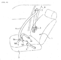
- Fig. 6 is a schematic perspective view of a three-point seatbelt apparatus disclosed in Patent Document 1.
- reference numeral 1 denotes a seat belt apparatus associated with a vehicle seat 2
- reference numeral 3 is a seat belt retractor fixed to a vehicle body near the vehicle seat 2 for withdrawably winding the seat belt 4 in the normal state and disabling withdrawing of the seat belt 4 in case of emergency
- reference numeral 5 denotes a tongue slidably supported by the seat belt 4
- reference numeral 6 denotes a buckle fixed to the vehicle seat 2 or the vehicle body for engaging the tongue
- reference numeral 7 denotes a belt guide mounted on the upper side portion of the vehicle such as a center pillar for guiding the seat belt 4 withdrawn from the seat belt retractor 3.
- a belt anchor 4a at a distal end of the seat belt 4 withdrawn from the seatbelt retractor 3 is fixed to the vehicle seat 2 or the vehicle body.
- the seat belt apparatus 1 in this structure when the passenger fasten the seat belt 4, the passenger seat on the vehicle seat 2, withdraws the seat belt 4 from the seatbelt retractor 3, engages the tongue 5 with the buckle 6, and releases his/her hand from the tongue 5, whereby part of the seatbelt 4 excessively withdrawn is retracted by the seat belt retractor 3 to solve sagging of the seat belt 4, and the seatbelt 4 is fastened on the passenger.
- the tongue 5 used on the seatbelt apparatus in the related art includes a metallic engaging strip 5a having an engaging hole 5a1 as shown in Fig. 7 and being engaged with the buckle 6 when a latch member (not shown) coming into engagement with an engagement hole 5a1 while the tongue 5 is inserted into the buckle 6, and a grip portion 5b molded of resin with part of the engaging strip 5a and a gripper 5b to be gripped for inserting and engaging the tongue 5 into/with the buckle 6.
- the seatbelt 4 being passed through a belt through hole 5b1 formed on the gripper 5b, the tongue 5 is slidably supported by the seatbelt apparatus 4.
- the engaging strip 5a is formed of a metallic plate as shown in Fig. 7, and the gripper 5b is formed of mold resin into a flat and substantially rectangular shape.
- the gripper 5b of the tongue 5 is formed into the flat and rectangular shape, the gripper 5b does not fit well to the passenger's hand when the passenger grips the gripper 5b for inserting and engaging into/with the buckle 6. Therefore, there are problems not only in that the passenger feels a sense of discomfort, but also in that the gripper 5b cannot be gripped easily. There are the same problems also in the case of the tongue used for the safety belt apparatus for protecting the personnel in the working site or the like.
- a tongue according to Claim 1 of the invention includes a gripper and an engaging strip projecting from the gripper, where the gripper is slidably supported by a safety belt, and the engaging strip is inserted and engaged into/with the buckle for constraining and protecting a user, the tongue being characterized in that a portion of an outer peripheral surface of the gripper except for a portion of the outer peripheral surface provided with the engaging strip so as to project therefrom is formed into a curved arc, and the portion of the peripheral surface provided with the engaging strip so as to project therefrom is formed into a chord that is continued from the curved arc, in that a surface of the gripper on one side is defined by a curved surface of a curved swelling shape and a planar surface formed continuously from the curved surface, and in that the curved surface is provided on a portion formed continuously from the outer peripheral surface formed into the shape of the curved arc, and the planar surface is formed to be continued from the outer peripheral surface formed into the linear chord and inclined from the
- the tongue according to Claim 3 of the invention includes a metallic tongue plate having the engaging strip and a through hole for the safety belt and being formed into a T-shape, a resin mold portion molded as a portion of the tongue plate formed with the through-hole for the safety belt, a lower cover for supporting the resin mold portion and the tongue plate, and an upper cover detachably engaging with the lower cover so as to cover the resin mold portion, characterized in that the surface of the upper cover on one side is defined by a curved surface of a curved swelling shape and a planar surface formed continuously from the curved surface, and in that the curved surface is provided on a portion formed continuously from the outer peripheral surface formed into a curved arc, and the planar surface is formed to be continued from the outer peripheral surface formed into the linear chord and inclined from the outer peripheral surface formed into the chord toward the swelling direction of the curved surface and away from the engaging strip.
- the tongue according to Claim 4 of the invention is further characterized in that a middle cover formed of opaque material is provided so as to cover the resin mold portion, the upper cover is provided so as to cover the middle cover, and is formed of a transparent material.
- a seatbelt apparatus according to Claim 5 of the invention at least includes a seatbelt, a seatbelt retractor for retracting the seatbelt, a tongue slidably supported by the seatbelt, and a buckle where the tongue is inserted and engaged, the seat belt being fastened on a passenger when the tongue is inserted and engaged into/with the buckle, the seatbelt apparatus being characterized in that the tongue is a tongue according to any one of Claims 1 to 4.
- the portion of the outer peripheral surface of the gripper except for the portion of the outer peripheral surface provided with the engaging strip so as to project therefrom is formed into the curved arc, so that it can be fitted substantially to an arcuate shape defined by two joints of four fingers and one joint of the thumb of the user. Since the surface of the gripper on one side is defined by a curved surface of a curved swelling shape and a planar surface formed continuously from the curved surface, and the curved surface on the other side is provided on the portion formed continuously from the outer peripheral surface formed into the shape of a curved arc, it can be fitted to the palm of the user. Accordingly, the entire gripper of the tongue can be formed into a shape that can be gripped by the user's hand without a feeling of discomfort.
- the planar surface of the gripper on the other side is formed to be continued from the outer peripheral surface formed into the linear chord and inclined from the outer peripheral surface formed into the chord toward the swelling direction of the curved surface and away from the engaging strip, a relatively large space can be formed between the curved swelling portion of the gripper of the tongue and the buckle in a state in which the tongue is inserted and engaged into/with the buckle. Therefore, when the user presses a release button of the buckle to release the tongue from the buckle, the user can easily enter his/her finger into the space. Accordingly, even when the gripper of the tongue is curved and swelled, the pressing operation of the release button can easily and reliably be performed.
- the outer contour of the gripper of the tongue is formed generally into a round shape, the appearance gives a feeling of soft and calm, and the appearance of the gripper can be improved.
- the gripper can be fitted effectively to the user's hand because the palm of the human is substantially close to the spherical shape.
- the upper cover is divided from other components and is detachably attached, by providing a number of upper covers having various shapes of curved surface and the outer peripheral surface, the tongue with the gripper which most fits the user can be obtained, and the tongue of the gripper according to the taste of the user can be obtained.
- the middle cover for covering the resin mold portion is opaque, so that the resin mold portion and the safety belt passing through the belt insertion hole are hidden from the eyes, the appearance of the gripper can further be improved.
- the upper cover is transparent so that the surface of the middle cover on the side of the upper cover can be seen, by providing an emblem or drawing patterns thereon, the appearance of the gripper can further be improved.
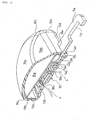
- the tongue 5 of this embodiment includes a tongue plate 11 formed of a metal plate.
- the tongue plate 11 is formed into a shape elongated in the direction of insertion of a buckle 6, and is arranged in substantially T-shape, consisting of the engagement strip 5a to be engaged with the buckle 6 and a body portion 12 formed in a shape elongated in the direction orthogonal to the direction of insertion of the buckle 6 for securing the strength of the gripper 5b of the tongue.
- the engaging strip 5a is formed with an engaging hole 5a1 with which a latch member of the buckle 6 engages as in the case of the related art described above, and the body portion 12 is formed with an elongated through hole 12a extending in the direction orthogonal to the direction of insertion of the buckle 6 for allowing passage of the seatbelt 4.
- the body portion 12 is molded with resin as in the case of the related art, and is covered by a flat and rectangular resin mold portion 13.
- the through-hole 12a of the body portion 12 is also molded with resin, and the resin mold portion 13 is formed with a belt through hole 5b1 to allow passage of the seat belt 4.
- the resin mold portion 13 is reinforced by the body portion 12, whereby the strength is secured.
- the body portion 12 and the resin mold portion 13 are placed on and supported by a lower cover 14 formed, for example, of opaque resin having a substantially annular shape.
- the lower cover 14 can also be formed of transparent resin, or of material other than resin, such as light metal as a matter of course.
- the resin mold portion 13 is adapted to be arranged in an opening 14a at a center of the lower cover 14. In this manner, in a state in which the resin mold portion 13 is arranged in the opening 14a, another belt through hole 5b2 is defined by an edge of the resin mold portion 13 on the opposite side from the engaging strip 5a and a guide portion 14b of the lower cover 14.
- the belt through hole 5b2 is formed into an elongated hole extending in parallel with, and in substantially the same size as, the belt through hole 5b1 formed on the resin mold portion 13.
- the middle cover 15 formed of opaque resin is placed so as to cover the body portion 12, resin mold portion 13, and part of the lower cover 14 from above.
- the upper surface portion 15a of the middle cover 15 is formed into a plate shape having an arcuate outer peripheral edge, and the arcuate outer peripheral edge is formed with an arcuate flange 15b, and the arcuate flange 15b comes into contact with the outer peripheral end of the upper surface of the lower cover 14.
- the outer peripheral edge of the upper surface portion 15a of the middle cover 15 where the engagement strip 5a projects is formed into a linear chord shape, and a linear flange 15c is formed on the chord-shaped outer peripheral edge.
- a rectangular notch 15d is formed on the linear flange 15c, so that the upper surface and the left and right side edge of the engagement strip 5 are fitted to the recess 15d without clearance.
- the middle cover 15 is formed with a cylindrical column 15e, and the cylindrical column 15e is adapted to be fitted to and engaged with an engaging hole 12b formed on the body portion 12.
- the upper cover 16 of transparent resin is placed so as to cover the middle cover 15 from above.
- the upper surface portion 16a of the upper cover 16 includes an arcuate outer peripheral edge, and is formed into a spherical shape swelling upward, and an arcuate flange 16b is continuously formed on the arcuate outer peripheral edge in the vertical direction.
- the size of the sphere swelling upwardly of the upper surface portion 16a is set to a size that fits an average size of a human palm
- the diameter of the arc of the flange 16b is set to a size that five fingers of a human hand of an average size exactly fit.
- the shape from the upper surface portion 16a to the flange 16b does not change abruptly, but changes gently to form an R-portion (curved surface portion) 16c in a relatively large radius.
- the inner peripheral surface of the arcuate flange 16b abuts against the outer peripheral surface of the lower cover 14 and the outer peripheral surface of the arcuate flange 15b of the middle cover 15.
- the outer peripheral edge of the upper surface portion 16a of the upper cover 16 where the engaging strip 5a projects is formed into a chord shape, and the linear flange 16d is formed on the chord-shaped outer peripheral edge in the vertical direction.
- the linear flange 16d is formed with a rectangular recess 16e so that the upper surface and the left and right side edges of the engaging strip 5a exactly fit in the recess 16e without clearance.
- the inner peripheral surface of the linear flange 16d abuts against the outer peripheral surface of the lower cover 14 where the engaging strip 5a projects and the outer peripheral surface of the linear flange 15c of the middle cover 15.
- the upper surface portion 16a1 formed continuously from the linear flange 16d is formed so as to incline toward the swelling direction of the spherical shape and away from the engaging strip 5a, and is formed continuously from the upper surface portion 16a of the spherical shape.
- the upper cover 16 is mounted to a lower cover 14 by detachably engaging an engaging portion, not shown, with the engaged portions 14c, 14d, 14e, 14f of the lower cover 14, for example, by snap engagement or the like.
- the gripper 5b of the tongue 5 including the resin mold portion 13 and the respective covers 14, 15, 16 is formed in this manner.
- the middle cover 15 is clamped between the upper cover 16 and the lower cover 14.
- the edge 13a of the resin mold 13 on the side of the engaging strip 5a comes into abutment with the edge 14g of the lower cover 14 on the side of the engaging strip 5a formed with the opening 14a and the cylindrical column 15e of the middle cover 15a fits the engaging hole 12b of the body portion 12, whereby the tongue plate 11 and the resin mold portion 13 are positioned with respect to the respective covers 14, 15, 16.
- the engaging strip 5a is firmly clamped between the two linear flanges 15c, 16d and the engaging strip supporting portion 14h of the lower cover 14. In this manner, the tongue 5 including the gripper 5b and the engaging strip 5a integrally assembled is completed.
- the upper surface portion 16a which swells upwardly in the spherical shape of the gripper 5b of the completed tongue 5 fits the palm of the passenger, and the outer peripheral surface including the arcuate flange 16b and the R-portion 16c thereof fits the five fingers of the passenger when two joints of the respective fingers are bent to a moderate degree, thereby providing a contour so as to allow the passenger to grip the gripper 5b easily by hand.
- the engaging strip 5a of the tongue 5 is projected from the gripper 5b.
- the seatbelt 4 extending from the belt anchor 4a fixed to the floor portion or the like of the vehicle body extends through the belt through hole 5b1, a space between the upper surface portion 15a of the middle cover 15 and the resin mold portion 13, and the belt through hole 5b2 to the belt guide 7.
- the tongue 5 is slidably supported by the seatbelt 4 as in the case of the tongue in the related art.
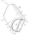
- the buckle 6 includes a cover having an upper cover 17 and a lower cover 18.
- the upper cover includes an upper surface 17a formed in relatively flat shape in contour and left and right side wall portions 17d, 17e connected to the upper surface 17a respectively through R portions 17b, 17c of relatively large diameter , and is formed into a semi-cylindrical shape.
- the lower cover 18 includes a flat bottom portion 18a, and left and right side wall portions 18b, 18c formed on both of the left and right side edges of the bottom portion 18a so as to extend in the vertical direction, and is formed into a U-shape in lateral cross section (although the left side wall portion 18b is not shown in Fig. 4, the reference numeral 18b is shown adjacently to the reference numeral 18c in parenthesis for the convenience of description).
- the left and right wall portions 17d, 17e of the upper cover and the left and right side wall portions 18b, 18c of the lower cover 18 are aligned respectively in the vertical direction, and then the upper cover 17 and the lower cover 18 are detachably engaged by, for example, snap engagement or the like, whereby generally cylindrical cover is formed.
- the end surface 17f of the upper cover 17 on the side of the insertion of the tongue 5 is formed into an inclined surface which extends away from the tongue 5 from the lower portion to the upper portion thereof.
- the upper cover 17 and the lower cover 18 engaged with respect to each other are formed into a cylindrical shape, and a release button 19 is provided on the side of the upper cover 17 inside the cylinder, and a tongue insertion port 20 is provided between the release button 19 and the lower cover 18.
- the side surface 19a of the release button 19 on the tongue 5 side is also inclined along the end surface 17f of the upper cover 17.
- the tongue 5 and the buckle 6 in this arrangement are engaged with each other by inserting the engaging strip 5a from the tongue insertion port 20 thereby engaging the latch member of the buckle 6 with the engaging hole 5a1 of the engaging strip 5a as in the case of the tongue in the related art.
- the upper cover 16 of the tongue 5 is provided with the upper surface portion 16a1 which is the flat inclined planar-shape, even when the upper surface portion 16a of the upper cover 16 is formed so as to swell upward, a relatively large space S is defined. Therefore, when the passenger presses the release button 19 for releasing the tongue 5 from the buckle 6, he/she can insert his/her finger into the space S easily. Accordingly, the pressing operation of the release button 19 can be performed easily and reliably.
- the space S is a relatively large space. Accordingly, releasing operation of the release button 19 by the finger is further facilitated.
- the space S is interposed between the both upper covers 16, 17, the release button 19 is hardly interfered with an object, whereby accidental release of engagement in the state in which the tongue 5 and the buckle 6 are engaged is prevented.
- the upper surface portion 16a of the gripper 5b of the tongue 5 is swelled upward in the spherical shape, it can be fitted to the palm of the passenger. Since the outer peripheral surface of the gripper 5b is formed by the arcuate flange 16b, it can be fitted to the arcuate shape formed by the respective two joints of the four fingers and one joint of the thumb of the passenger, respectively. In addition, since the portion between the upper surface portion 16a and the flange 16b of the gripper 5b is the R-portion 16c, the R-portion 16c can be fitted to the five respective fingers which are bent moderately. Accordingly, the entire gripper 5b of the tongue 5 can be formed into a contour which can be gripped by the passenger's hand without giving a feeling of discomfort.
- the inclined upper surface portion 16a1 of the gripper 5b is inclined toward the swelling direction of the spherical shape away from the engaging strip 5a, the relatively large space S can be defined between the curved swelling portion of the gripper 5b of the tongue 5 and the buckle 6 in a state in which the tongue 5 is inserted into and engaged with the buckle 6. Therefore, when the passenger presses the release button 19 of the buckle 6 for releasing engagement of the tongue 5 from the buckle 6, the passenger can easily insert his/her finger into the space S. Accordingly, even when the gripper 5b of the tongue 5b is formed into the spherical shape, pressing operation of the release button 19 can be performed easily and reliably.
- the contour of the gripper 5b of the tongue 5 is formed generally into a round shape, the appearance gives a feeling of soft and sedate, whereby the appearance of the gripper 5b can be improved.
- the upper cover 16 is formed separately from other components and is detachably provided, by providing a number of the upper covers 16 having various shapes of the spherical surface and the arc of the outer peripheral surface, the tongue 5 with the gripper 5b which most fits the passenger's hand can be obtained, and the tongue 5 with the gripper 5b which meets the taste of the passenger can be also obtained.
- the middle cover 15 for covering the resin mold portion 13 is opaque, so that the resin mold portion 13 and the seat belt 4 passing through the two belt through holes 5b1, 5b2 are hidden from the eyes, the appearance of the gripper 5b can further be improved. Furthermore, since the upper cover 16 is transparent so that the upper surface of the upper surface portion 15a of the middle cover 15 can be seen, by providing the emblem or drawing patterns thereon, the appearance of the gripper 5b can further be improved.
- the passenger seated on the vehicle seat 2 can easily grip the tongue 5 by employing the tongue 5 of this embodiment as the tongue 5 of the seatbelt apparatus 1, insertion and engagement of the tongue 5 into/with the buckle 6 by the passenger is facilitated.
- the upper surface portion 16a of the gripper 5b of the tongue 5 is formed into the spherical shape, and the outer peripheral surface of the gripper 5b is formed into the arcuate shape.
- the present invention is not limited thereto, and it is also possible to form the upper surface portion 16a into a curved surface of curved swelling such as an egg shape, and the outer peripheral surface of the gripper 5b is formed into a curved arc such as the oval arcuate shape.
- forming the curved surface of the curved swelling shape of the gripper 5b into a spherical shape allows the gripper 5b to effectively fit to the passenger's hand, since the human palm is substantially close to the spherical shape.
- the tongue 5 of this embodiment can be used for the safety belt apparatus for constraining and protecting, for example, the personnel in the working site, and the same effects can be obtained.
- the tongue of the present invention can be used effectively as a tongue used in the seatbelt for protecting the passenger seated on the seat of the vehicle such as the motor vehicle and in the safety belt apparatus for protecting the personnel in the working site or the like.
Landscapes
- Automotive Seat Belt Assembly (AREA)
Applications Claiming Priority (1)
| Application Number | Priority Date | Filing Date | Title |
|---|---|---|---|
| JP2004322216A JP2006131087A (ja) | 2004-11-05 | 2004-11-05 | タングおよびこれを用いたシートベルト装置 |
Publications (2)
| Publication Number | Publication Date |
|---|---|
| EP1654948A1 true EP1654948A1 (fr) | 2006-05-10 |
| EP1654948B1 EP1654948B1 (fr) | 2008-03-12 |
Family
ID=35709364
Family Applications (1)
| Application Number | Title | Priority Date | Filing Date |
|---|---|---|---|
| EP05020137A Expired - Lifetime EP1654948B1 (fr) | 2004-11-05 | 2005-09-15 | Une Languette avec un pince et ceinture de securité utilisant celui-ci |
Country Status (5)
| Country | Link |
|---|---|
| US (1) | US20060097503A1 (fr) |
| EP (1) | EP1654948B1 (fr) |
| JP (1) | JP2006131087A (fr) |
| CN (1) | CN1768635A (fr) |
| DE (1) | DE602005005265T2 (fr) |
Cited By (1)
| Publication number | Priority date | Publication date | Assignee | Title |
|---|---|---|---|---|
| EP1754637A3 (fr) * | 2005-08-19 | 2008-04-30 | Takata Corporation | Dispositif de ceinture de sécurité |
Families Citing this family (7)
| Publication number | Priority date | Publication date | Assignee | Title |
|---|---|---|---|---|
| CN2935902Y (zh) * | 2006-01-28 | 2007-08-22 | 利富高(香港)有限公司 | 带扣 |
| GB0920806D0 (en) * | 2009-11-27 | 2010-01-13 | Cox Graham E | Improvements in and relating to seat belts |
| EP2554072B1 (fr) * | 2010-03-30 | 2016-02-10 | Ashimori Industry Co., Ltd. | Languette |
| EP2377417B1 (fr) * | 2010-04-15 | 2013-01-02 | Volvo Car Corporation | Loquet de ceinture pour ceinture de sécurité |
| JP5708568B2 (ja) * | 2012-06-15 | 2015-04-30 | トヨタ自動車株式会社 | タングプレート及び車両用シートベルト装置 |
| DE202012012254U1 (de) * | 2012-12-20 | 2013-02-22 | Key Safety Systems, Inc. | Gurtschloss für einen Fahrzeugsicherheitsgurt |
| US10512310B2 (en) | 2018-02-05 | 2019-12-24 | Autoliv Asp, Inc. | Noise dampening tongues for use in a seat belt restraining system and methods of making the same |
Citations (5)
| Publication number | Priority date | Publication date | Assignee | Title |
|---|---|---|---|---|
| US3897611A (en) * | 1972-10-02 | 1975-08-05 | Allied Chem | Ejection tongue for buckle |
| US4606552A (en) * | 1984-03-23 | 1986-08-19 | Broderna Holmbergs Fabriks Ab | Lock for safety belts |
| JPH0355228B2 (fr) | 1985-04-26 | 1991-08-22 | ||
| US5214827A (en) * | 1991-07-19 | 1993-06-01 | Takata Corporation | Seat belt tongue |
| US20010025400A1 (en) * | 2000-03-09 | 2001-10-04 | Jens Romca | Passenger chair and safety belt system for such a chair |
Family Cites Families (4)
| Publication number | Priority date | Publication date | Assignee | Title |
|---|---|---|---|---|
| US4167054A (en) * | 1975-12-03 | 1979-09-11 | Toyota Jidosha Kogyo Kabushiki Kaisha | Tongue plate device for use in seat belt system |
| US4962572A (en) * | 1989-02-22 | 1990-10-16 | Trw Vehicle Safety Systems Inc. | Tongue assembly |
| JPH06217807A (ja) * | 1993-01-26 | 1994-08-09 | Takata Kk | 自動バックル装置 |
| US5983463A (en) * | 1998-06-17 | 1999-11-16 | Breed Automotive Technology, Inc. | Latchplate or tongue assembly with dual mode of operation |
-
2004
- 2004-11-05 JP JP2004322216A patent/JP2006131087A/ja not_active Withdrawn
-
2005
- 2005-09-15 DE DE602005005265T patent/DE602005005265T2/de not_active Expired - Fee Related
- 2005-09-15 EP EP05020137A patent/EP1654948B1/fr not_active Expired - Lifetime
- 2005-11-01 CN CN200510118624.4A patent/CN1768635A/zh active Pending
- 2005-11-02 US US11/264,016 patent/US20060097503A1/en not_active Abandoned
Patent Citations (5)
| Publication number | Priority date | Publication date | Assignee | Title |
|---|---|---|---|---|
| US3897611A (en) * | 1972-10-02 | 1975-08-05 | Allied Chem | Ejection tongue for buckle |
| US4606552A (en) * | 1984-03-23 | 1986-08-19 | Broderna Holmbergs Fabriks Ab | Lock for safety belts |
| JPH0355228B2 (fr) | 1985-04-26 | 1991-08-22 | ||
| US5214827A (en) * | 1991-07-19 | 1993-06-01 | Takata Corporation | Seat belt tongue |
| US20010025400A1 (en) * | 2000-03-09 | 2001-10-04 | Jens Romca | Passenger chair and safety belt system for such a chair |
Cited By (1)
| Publication number | Priority date | Publication date | Assignee | Title |
|---|---|---|---|---|
| EP1754637A3 (fr) * | 2005-08-19 | 2008-04-30 | Takata Corporation | Dispositif de ceinture de sécurité |
Also Published As
| Publication number | Publication date |
|---|---|
| DE602005005265D1 (de) | 2008-04-24 |
| EP1654948B1 (fr) | 2008-03-12 |
| CN1768635A (zh) | 2006-05-10 |
| JP2006131087A (ja) | 2006-05-25 |
| US20060097503A1 (en) | 2006-05-11 |
| DE602005005265T2 (de) | 2008-06-19 |
Similar Documents
| Publication | Publication Date | Title |
|---|---|---|
| US4939824A (en) | Vehicle safety belt buckle cover | |
| EP1754637B1 (fr) | Dispositif de ceinture de sécurité | |
| US5659897A (en) | Baseball glove with thumb member | |
| US5197176A (en) | Seat belt guide useful in securing a child safety restraint | |
| JP6344802B2 (ja) | 係止具を備えたマスク | |
| EP2504202B1 (fr) | AMÉLIORATIONS APPORTÉES À DES CEINTURES DE SÉCURITÉ ET RELATIVES À & xA;CELLES-CI | |
| EP1654948B1 (fr) | Une Languette avec un pince et ceinture de securité utilisant celui-ci | |
| US5088163A (en) | Belt lock | |
| JP2017193802A5 (fr) | ||
| EP4374731A1 (fr) | Boucle avec sifflet | |
| EP2660107B1 (fr) | Dispositif de ceinture de sécurité | |
| EP1857007A2 (fr) | Ancre de sécurité pour fixations | |
| JP7130235B2 (ja) | シートベルト誤操作防止具 | |
| JP4524518B2 (ja) | ウェビング挿通部材 | |
| JPH08156741A (ja) | ウェビング走行方向転換部材 | |
| JP2012102436A (ja) | 帽体用顎紐連結構造 | |
| JP3689631B2 (ja) | シートベルト装置 | |
| JPH11180251A (ja) | 車輌用シート | |
| JPH0214523Y2 (fr) | ||
| KR200159213Y1 (ko) | 자동차 도어 아우터 사이드 핸들의 보조손잡이 | |
| JPS604841Y2 (ja) | シ−トベルト引出孔を備えた車輛用座席 | |
| JPH0716529Y2 (ja) | シートプロテクター | |
| JP3005977B2 (ja) | ヘルメット | |
| JPH0740447Y2 (ja) | エネルギー吸収式シートベルト装置 | |
| JPH0336272Y2 (fr) |
Legal Events
| Date | Code | Title | Description |
|---|---|---|---|
| PUAI | Public reference made under article 153(3) epc to a published international application that has entered the european phase |
Free format text: ORIGINAL CODE: 0009012 |
|
| AK | Designated contracting states |
Kind code of ref document: A1 Designated state(s): AT BE BG CH CY CZ DE DK EE ES FI FR GB GR HU IE IS IT LI LT LU LV MC NL PL PT RO SE SI SK TR |
|
| AX | Request for extension of the european patent |
Extension state: AL BA HR MK YU |
|
| 17P | Request for examination filed |
Effective date: 20060905 |
|
| AKX | Designation fees paid |
Designated state(s): DE FR GB SE |
|
| 17Q | First examination report despatched |
Effective date: 20061109 |
|
| GRAP | Despatch of communication of intention to grant a patent |
Free format text: ORIGINAL CODE: EPIDOSNIGR1 |
|
| GRAS | Grant fee paid |
Free format text: ORIGINAL CODE: EPIDOSNIGR3 |
|
| GRAA | (expected) grant |
Free format text: ORIGINAL CODE: 0009210 |
|
| AK | Designated contracting states |
Kind code of ref document: B1 Designated state(s): DE FR GB SE |
|
| REG | Reference to a national code |
Ref country code: GB Ref legal event code: FG4D |
|
| REF | Corresponds to: |
Ref document number: 602005005265 Country of ref document: DE Date of ref document: 20080424 Kind code of ref document: P |
|
| REG | Reference to a national code |
Ref country code: SE Ref legal event code: TRGR |
|
| ET | Fr: translation filed | ||
| PLBE | No opposition filed within time limit |
Free format text: ORIGINAL CODE: 0009261 |
|
| STAA | Information on the status of an ep patent application or granted ep patent |
Free format text: STATUS: NO OPPOSITION FILED WITHIN TIME LIMIT |
|
| PGFP | Annual fee paid to national office [announced via postgrant information from national office to epo] |
Ref country code: DE Payment date: 20081031 Year of fee payment: 4 |
|
| 26N | No opposition filed |
Effective date: 20081215 |
|
| REG | Reference to a national code |
Ref country code: FR Ref legal event code: ST Effective date: 20090529 |
|
| PG25 | Lapsed in a contracting state [announced via postgrant information from national office to epo] |
Ref country code: FR Free format text: LAPSE BECAUSE OF NON-PAYMENT OF DUE FEES Effective date: 20080930 |
|
| GBPC | Gb: european patent ceased through non-payment of renewal fee |
Effective date: 20090915 |
|
| PG25 | Lapsed in a contracting state [announced via postgrant information from national office to epo] |
Ref country code: SE Free format text: LAPSE BECAUSE OF NON-PAYMENT OF DUE FEES Effective date: 20080916 Ref country code: DE Free format text: LAPSE BECAUSE OF NON-PAYMENT OF DUE FEES Effective date: 20100401 |
|
| PG25 | Lapsed in a contracting state [announced via postgrant information from national office to epo] |
Ref country code: GB Free format text: LAPSE BECAUSE OF NON-PAYMENT OF DUE FEES Effective date: 20090915 |