EP1655244B1 - Verfahren und Vorrichtung zur Vereinzelung von flachen Gegenständen aus einem liegenden Stapel - Google Patents
Verfahren und Vorrichtung zur Vereinzelung von flachen Gegenständen aus einem liegenden Stapel Download PDFInfo
- Publication number
- EP1655244B1 EP1655244B1 EP05405532A EP05405532A EP1655244B1 EP 1655244 B1 EP1655244 B1 EP 1655244B1 EP 05405532 A EP05405532 A EP 05405532A EP 05405532 A EP05405532 A EP 05405532A EP 1655244 B1 EP1655244 B1 EP 1655244B1
- Authority
- EP
- European Patent Office
- Prior art keywords
- stack
- away
- articles
- conveying
- upwards
- Prior art date
- Legal status (The legal status is an assumption and is not a legal conclusion. Google has not performed a legal analysis and makes no representation as to the accuracy of the status listed.)
- Expired - Lifetime
Links
Images



Classifications
-
- B—PERFORMING OPERATIONS; TRANSPORTING
- B65—CONVEYING; PACKING; STORING; HANDLING THIN OR FILAMENTARY MATERIAL
- B65G—TRANSPORT OR STORAGE DEVICES, e.g. CONVEYORS FOR LOADING OR TIPPING, SHOP CONVEYOR SYSTEMS OR PNEUMATIC TUBE CONVEYORS
- B65G17/00—Conveyors having an endless traction element, e.g. a chain, transmitting movement to a continuous or substantially-continuous load-carrying surface or to a series of individual load-carriers; Endless-chain conveyors in which the chains form the load-carrying surface
- B65G17/30—Details; Auxiliary devices
- B65G17/32—Individual load-carriers
- B65G17/323—Grippers, e.g. suction or magnetic
-
- B—PERFORMING OPERATIONS; TRANSPORTING
- B65—CONVEYING; PACKING; STORING; HANDLING THIN OR FILAMENTARY MATERIAL
- B65G—TRANSPORT OR STORAGE DEVICES, e.g. CONVEYORS FOR LOADING OR TIPPING, SHOP CONVEYOR SYSTEMS OR PNEUMATIC TUBE CONVEYORS
- B65G59/00—De-stacking of articles
- B65G59/08—De-stacking after preliminary tilting of the stack
-
- B—PERFORMING OPERATIONS; TRANSPORTING
- B65—CONVEYING; PACKING; STORING; HANDLING THIN OR FILAMENTARY MATERIAL
- B65H—HANDLING THIN OR FILAMENTARY MATERIAL, e.g. SHEETS, WEBS, CABLES
- B65H3/00—Separating articles from piles
- B65H3/08—Separating articles from piles using pneumatic force
- B65H3/0808—Suction grippers
-
- B—PERFORMING OPERATIONS; TRANSPORTING
- B65—CONVEYING; PACKING; STORING; HANDLING THIN OR FILAMENTARY MATERIAL
- B65H—HANDLING THIN OR FILAMENTARY MATERIAL, e.g. SHEETS, WEBS, CABLES
- B65H3/00—Separating articles from piles
- B65H3/40—Separating articles from piles by two or more separators acting alternately on the same pile
-
- B—PERFORMING OPERATIONS; TRANSPORTING
- B65—CONVEYING; PACKING; STORING; HANDLING THIN OR FILAMENTARY MATERIAL
- B65H—HANDLING THIN OR FILAMENTARY MATERIAL, e.g. SHEETS, WEBS, CABLES
- B65H5/00—Feeding articles separated from piles; Feeding articles to machines
- B65H5/08—Feeding articles separated from piles; Feeding articles to machines by grippers, e.g. suction grippers
- B65H5/085—Feeding articles separated from piles; Feeding articles to machines by grippers, e.g. suction grippers by combinations of endless conveyors and grippers
-
- B—PERFORMING OPERATIONS; TRANSPORTING
- B65—CONVEYING; PACKING; STORING; HANDLING THIN OR FILAMENTARY MATERIAL
- B65H—HANDLING THIN OR FILAMENTARY MATERIAL, e.g. SHEETS, WEBS, CABLES
- B65H2301/00—Handling processes for sheets or webs
- B65H2301/30—Orientation, displacement, position of the handled material
- B65H2301/32—Orientation of handled material
- B65H2301/321—Standing on edge
-
- B—PERFORMING OPERATIONS; TRANSPORTING
- B65—CONVEYING; PACKING; STORING; HANDLING THIN OR FILAMENTARY MATERIAL
- B65H—HANDLING THIN OR FILAMENTARY MATERIAL, e.g. SHEETS, WEBS, CABLES
- B65H2301/00—Handling processes for sheets or webs
- B65H2301/40—Type of handling process
- B65H2301/42—Piling, depiling, handling piles
- B65H2301/423—Depiling; Separating articles from a pile
- B65H2301/4237—Depiling; Separating articles from a pile of vertical articles, e.g. by extracting articles laterally from the pile
- B65H2301/42372—Depiling; Separating articles from a pile of vertical articles, e.g. by extracting articles laterally from the pile by extracting articles upwards from the pile
-
- B—PERFORMING OPERATIONS; TRANSPORTING
- B65—CONVEYING; PACKING; STORING; HANDLING THIN OR FILAMENTARY MATERIAL
- B65H—HANDLING THIN OR FILAMENTARY MATERIAL, e.g. SHEETS, WEBS, CABLES
- B65H2301/00—Handling processes for sheets or webs
- B65H2301/40—Type of handling process
- B65H2301/44—Moving, forwarding, guiding material
- B65H2301/447—Moving, forwarding, guiding material transferring material between transport devices
- B65H2301/4471—Grippers, e.g. moved in paths enclosing an area
- B65H2301/44712—Grippers, e.g. moved in paths enclosing an area carried by chains or bands
-
- B—PERFORMING OPERATIONS; TRANSPORTING
- B65—CONVEYING; PACKING; STORING; HANDLING THIN OR FILAMENTARY MATERIAL
- B65H—HANDLING THIN OR FILAMENTARY MATERIAL, e.g. SHEETS, WEBS, CABLES
- B65H2301/00—Handling processes for sheets or webs
- B65H2301/40—Type of handling process
- B65H2301/44—Moving, forwarding, guiding material
- B65H2301/447—Moving, forwarding, guiding material transferring material between transport devices
- B65H2301/4472—Suction grippers, e.g. moved in paths enclosing an area
-
- B—PERFORMING OPERATIONS; TRANSPORTING
- B65—CONVEYING; PACKING; STORING; HANDLING THIN OR FILAMENTARY MATERIAL
- B65H—HANDLING THIN OR FILAMENTARY MATERIAL, e.g. SHEETS, WEBS, CABLES
- B65H2403/00—Power transmission; Driving means
- B65H2403/50—Driving mechanisms
- B65H2403/54—Driving mechanisms other
- B65H2403/543—Driving mechanisms other producing cycloids
Definitions
- the invention is in the field of general cargo handling and relates to a method and a device according to the preambles of the corresponding independent claims.
- Method and apparatus are used for separating flat objects from a horizontal stack, and are eg from the documents US 6,503,180 B1 and WO 02/30753 A1 known.
- horizontal stack is to be understood as meaning a multiplicity of flat objects, which are lined up with one edge on a horizontal or oblique (eg slightly sloping) stack support with substantially parallel main surfaces close to one another
- individual objects are removed one after the other from the top end of the stack, wherein a suitable tracking of the stack ensures that the top end of the stack is stationary.
- a device for separating flat objects from a horizontal stack is known, for example, from US Pat Patent EP-1099632 (respectively. US 6494310 , F514).
- This device has at the head end of the stack support, on which the flat objects stand up, a rotating suction wheel, the circumference of which moves immediately in front of the stack head end substantially perpendicular to the top (parallel to the main surfaces of the stacked objects). The foremost one The stack object is pushed against the suction wheel circumference by the stacking guide and sucked onto it, such that it is held on the suction wheel and slid over the stack upwards in relation to the follower object, away from the stack support.
- the suction at the Saugrador is controlled so that the follower object is sucked and lifted only when the leading object has already reached the stack.
- EP-1099632 proposed to separate in the stack foremost item group by force from a rear stacking area and move as a relatively looser stack on a slightly sloping and vibrating stack support against the head end. This ensures that acting against the head end, the objects pressed against each other and against the head end forces and thus the friction between the objects remains low and the separation can be performed reliably in said, very simple apparatus.
- the device according to EP-1099632 is for the reasons mentioned only applicable for the separation of relatively stable objects that can stand upright on an edge in a very loose pile. In this case, the greater the coefficient of friction between the objects, the looser the stack must be.
- the device also makes further demands on the mechanical stability of the objects to be separated in that they by the suction wheel, its scope Moving at a constant speed substantially perpendicular to the stack support, are accelerated almost abruptly, which sensitive objects could be undesirably deformed or even damaged, especially when high unit performance is to be achieved by a high Saugrad für.
- the suction wheel or the control of a suction cycle to the height of the objects on the stack support and, where appropriate, to adapt to their width, that is, the suction wheel may need to be physically adapted for the processing of different article formats.
- the object of the invention is now to provide a method and a device for separating flat objects from a horizontal stack, wherein it should be possible without adjustment when using the method and device according to the invention with respect to mechanical strength and stiffness and / or Format significantly more different types of objects to handle, as is the case with corresponding, known devices and methods that serve the same purpose.
- the separation according to the invention from a horizontal stack is based, as is the case with known singular separations, on a displacement of the stack lying in front of the foremost object upwards and advantageously at a constant speed.
- a preparatory step is preceded by such upward conveying, in which the foremost object is first detected, in which the detected object is then separated in a direction substantially perpendicular to its main surfaces from the top of the stack and in which the from the stack separated object is then accelerated upwards, wherein use the acceleration with the separation or immediately after it. Only when the object has a sufficiently large velocity component directed upwards parallel to its main surfaces is it taken over by a means of displacement at a constant speed and conveyed further upwards.
- the object to be separated from the stack head end is pressed against the stack when it is detected and thereby stabilized for this detection on the stack, so that even relatively unstable objects can be reliably detected.
- the pressing force directed against the stack head end in the stack can be adjusted independently of the separation to other conditions (for example inherent rigidity of the objects).
- the preparatory step of the separation according to the invention preceding the removal of the path is advantageously carried out with the aid of a suction device connected to a controllable suction line, wherein the suction device advantageously has an elastically deformable suction lip.
- the nipple is moved along a suction path against the head end of the stack and then away therefrom, the suction path having a reversal point in the region of the stack head end. At least in the immediate vicinity of the turning point, the suction path is substantially transverse to the major surfaces of the stacked objects.
- the leading away from the turning point Saugerbahnteil then turns continuously or not continuously against the top.
- the position of the point of reversal is chosen such that the teat, when positioned at the point of reversal, is pressed against the foremost object so that its squeegee fits snugly against this object and it can be evacuated.
- a plurality of suckers acting alternately in the above-mentioned manner may also be used.
- the suction movement along said suction path is realized for example in a conventional manner by means of articulated or cam gear, wherein one or more suckers can be articulated to such a transmission.
- Stack support and suction are advantageously arranged relative to each other, that the stack is aligned regardless of the format of the objects to be separated on a stationary, lateral stop and that the sucker so close to the stack support and the lateral stop on the object to be detected hits that he can also detect expected items with small formats, without having to be adjusted accordingly.
- the position of the reversal point is advantageously adjustable relative to the stack head end depending on the type of object to be handled, but this can be achieved with very simple means.
- suckers and grippers are synchronized in such a way that, on acceptance, the sucker has a speed component in the direction of the gripper movement which has the same order of magnitude as the gripper speed, advantageously being slightly smaller than the gripper speed.
- the gripper acts advantageously on that edge of the object, which is aligned on the lateral stop and thus has a format-independent position, so that the gripper and its path does not have to be set format dependent.
- FIG. 1 shows a very schematic representation of the inventive singling (view parallel to the main surfaces of the stacked objects).
- the head end 1 of a horizontal stack 2 in which the flat objects 3 on one of its edges on a, for example, against the stack head end sloping stack support 4 standing and pushed in a feed direction Z against each other against the stack head end 1 promoted.
- the suction 5.1 and 5.2 alternately lead the way promotion against the above preparatory step (foremost item capture, disconnect from the stack and accelerate against the top) and are for this purpose one behind the other along the suction path S moves.
- the gripper conveyor 6 serves as an exemplary removal means and has equidistant, in the removal direction W upwardly moving gripper 7.
- FIG. 1 represents a snapshot.
- the first sucker 5.1 is in the detection position, that is positioned at the reversal point U and pressed against the stack head end 1.
- the first sucker has achieved this position by movement along a first Saugerbahnteils S.1, wherein at least the end of this first Saugerbahnteils S.1 is aligned perpendicular to the main surfaces of the stacked objects 3.
- the first sucker is evacuated.
- the second sucker 5.2 is shown in the transfer position, that is, at a point where the second Saugerbahnteil S.2 or the web of the object detected by the sucker crosses the path of the Wegkeepmnittels (eg gripper transporter 6) and the object to one with the second Suction cup 5.2 correspondingly synchronized gripper 7 can be passed.
- the upward velocity component of the nipple 5.2 is similar in size to the gripper speed, advantageously somewhat smaller, such that the gripper 7 overtakes the nipple 5.2 before taking over from below while the article held by the nipple is introduced into the open gripper mouth. Then the gripper 7 is closed and the sucker 5.2 ventilated.
- the stack head 1 has a stationary position during operation. But since the suction path S, or the reversal point U between the first and the second Saugerbahnteil is advantageously matched to the consistency of the items to be separated (for harder objects in the FIG. 1 more left than for softer objects), the position of the stack head end 1 is advantageously adjustable with a change of the object type relative to the transfer position in the manner indicated by the double arrow E way. Smaller differences in consistency between article types can be compensated for by the deformability of the teat lip without appropriate adjustment of the stack head end.
- FIG. 2 shows schematically seen from the stack head end, as the gripper 7 takes the object 3 of the format independently oriented edge (stop indicated by dotted line) forth and laterally offset to the sucker 5.2. Also in FIG. 2 shown are also synchronized with the gripper 7 and moving on parallel paths to the gripper track support cam 10, with which in particular not very rigid objects at its trailing edge, the gripper can be supported supporting from below. Out FIG. 2 It can also be seen that for a change from a smaller, rectangular object type 3.1 to a larger, rectangular object type 3.2 or to a round opposite-edge type 3.3, neither suckers nor grippers have to be set.
- the Saugerbahn S of which in the FIG. 1 only the relevant for the detection of the object and its separation and acceleration parts (end of the first Saugerbahnteils S.1 and the beginning of the second Saugerbahnteils) are shown, is advantageously self-contained, such that the sucker for the transfer of a detected object for Wegparticularly be moved against the stack head end 1 again.
- FIGS. 4 to 7 show a preferred self-contained suction web S.
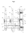
- FIG. 3 shows a preferred embodiment of the inventive device in a section parallel to the main surfaces of the stacked objects, wherein the cutting plane is behind the stack head end and the viewing direction is directed against the transfer position.
- FIG. 3 shows the stack support 4, the suction cups (5.1 in the detection position and 5.2 on the way back from the transfer position to the detection position) and as a Wegsellstoff the gripper conveyor 6 with grippers.
- FIG. 3 also shows a gripper function controlling scenery 30 with gate end 31, in connection with the FIG. 8 to be received.
- dash-dot two types 3.1 and 3.2 are indicated by flat objects. These objects are shown in the position of the head end of the stack, so struck with one edge on the stack support 4 and struck with a further edge on a lateral stop 20.
- the device according to FIG. 3 also has a counter-stop 21 corresponding to the lateral stop 20, as well as stabilizing means acting on different edges or edge regions for stabilizing the stack head end, here for example in the form of lateral brushes 22 and 23 and a foot strip 24. While stop 20 and lateral brush 22 on the abutment page are stationarily positioned independently of format, counter-stop 21 and side brush 23 on the opposite side by shifting to different format widths are adaptable (solid positions 21 and 23 for object type 3.1, dotted lines positions 21 'and 23' for object type 3.2).
- the path support provided by the gripper 7 supportive support means are advantageously, as already in connection with the FIG. 2 mentioned, the path support provided by the gripper 7 supportive support means.
- These have in the present case circumferentially driven support belts 25.1, 25.2 and 25.3, at least in the illustrated Weghold Scheme parallel to the gripper conveyor 6 and are driven at the same speed as this.
- the support belts 25.1 to 25.3 may be provided with support cams 10 which protrude from the belts and support the trailing (lower) object edges.
- the grippers 7 of the device according to FIG. 3 are formed as the side of a circumferentially driven gripper belt 6.1 protruding pressing elements 7.1, which are pressed against the arranged between the suction and gripper belt 6.1 support belt 25.1.
- the pressing element 7.1 In the “closed” state, the pressing element 7.1 is pressed by the spring 7.2 against the support belt or against an object supported on it, in the “open” state, the pressing element 7.1 through the gate 30 against the closing force of the spring 7.2 in one of the support belt 25.1 held in a distanced position.
- the gripper 7 designed as a pressing element 7.1
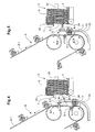
- FIGS. 4 to 7 show the device according to FIG. 3 as a side view (ie with a view parallel to the main surfaces of the stacked objects) in successive stages of separation.
- Like device parts are designated by the same reference numerals as in FIG FIG. 3 ,
- FIG. 4 shows the first sucker 5.1 at the beginning of the first Saugerbahnteils S.1, so ready to be moved along this Saugerbahnteils against the stack head end 1.
- the first sucker 5.1 has reached the end of the first Saugerbahnteils S.1, ie the reversal point U, and is thus in detection position. That is, it is pressed against the foremost object 3 to be detected and evacuated to then be moved along with the detected object 3 along the second Saugerbahnteils S.2 from the stack head end 1 away and up.
- FIG. 6 the first sucker has reached the transfer position.
- the synchronized with the sucker gripper 7 is relative to the object to be acquired for the acquisition (see FIG. 2 ).
- the gripper 7 is now closed and immediately thereafter or at the same time the sucker 5.1 is vented.
- FIG. 7 is the first sucker 5.1 on the third Saugerbahnteil S.3, along which he returns to the starting position FIG. 4 is moved.
- the gripped by the gripper 7 object 3 is held by the gripper 7 and supported by the support belt (not visible) and the support cam 10 carried away against the top.
- the second gripper 5.2 moves with a phase shift of 180 ° along the same suction path S as the first sucker. Each sucker thus performs the preparatory step on every other object.
- FIGS. 4 to 7 show a preferred, self-contained suction web S, which is substantially triangular and in addition to the reversal point U in the region of the stack head end 1 has two further reversal points U.1 and U.2, which are further spaced from the stack head end 1 as the transfer position. Between the reversal points U, U. 1 and U.2, the suction web S is in each case arcuate. It forms as a whole an isosceles triangle with concavely curved sides, whose Vertex of the reversal point U in the region of the stack head end 1 is.
- Such a suction path can be realized, for example, with suckers which are articulated on a joint or cam mechanism.
- FIG. 8 shows in the conveying direction already in connection with the FIG. 3 addressed gripper 7, which is designed as a pressing element 7.1 and arranged on a gripper belt 6.1.
- the pressing element is pressed by the spring 7.2 against the support belt 25.1.
- FIG. 8 shows the gripper 7 in the open state, in which the pressing element is kept 7.1 against the force of the spring 7.2 spaced from the support belt 25.1, characterized in that the control roller 7.3 rolls on the correspondingly arranged link 30.
- the scenery 30 stops (scenery end 31 in FIGS. 3 to 7 ), or correspondingly further away from the gripper belt 6.1, brings the spring 7.2, the pressing element in its pressing position in which it is pressed against the support belt 25.1 or against a wegzu busynden object.
Landscapes
- Engineering & Computer Science (AREA)
- Mechanical Engineering (AREA)
- Sheets, Magazines, And Separation Thereof (AREA)
- Pile Receivers (AREA)
Description
- Die Erfindung liegt auf dem Gebiete der Stückguthandhabung und betrifft ein Verfahren und eine Vorrichtung nach den Oberbegriffen der entsprechenden, unabhängigen Patentansprüche. Verfahren und Vorrichtung dienen zur Vereinzelung von flachen Gegenständen aus einem liegenden Stapel, und sind z.B. aus der Dokumente
US 6,503,180 B1 undWO 02/30753 A1 - Unter dem Begriff ,,liegender Stapel" soll im Folgenden eine Vielzahl von flachen Gegenständen verstanden werden, die mit einer Kante auf einer horizontalen oder schiefen (z.B. leicht abfallenden) Stapelauflage aufstehend mit im wesentlichen parallelen Hauptflächen dicht aneinander gereiht sind. Zur Vereinzelung der Gegenstände aus einem derartigen Stapel werden vom Kopfende des Stapels einzelne Gegenstände nacheinander entfernt, wobei durch eine geeignete Nachführung des Stapels dafür gesorgt wird, dass das Kopfende des Stapels stationär ist.
- Eine Vorrichtung zur Vereinzelung von flachen Gegenständen aus einem liegenden Stapel ist beispielsweise bekannt aus der
Patentschrift EP-1099632 (bzw.US-6494310 , F514). Diese Vorrichtung weist am Kopfende der Stapelauflage, auf der die flachen Gegenstände aufstehen, ein rotierendes Saugrad auf, dessen Umfang sich unmittelbar vor dem Stapelkopfende im wesentlichen senkrecht gegen oben (parallel zu den Hauptflächen der gestapelten Gegenstände) bewegt. Der jeweils vorderste Gegenstand des Stapels wird durch die Stapelnachführung gegen den Saugradumfang gestossen und an diesen angesaugt, derart, dass er am Saugrad gehalten und gegenüber dem Folgegegenstand rutschend von der Stapelauflage weg über den Stapel angehoben wird. Die Saugwirkung am Saugradumfang wird derart gesteuert, dass der Folgegegenstand erst angesaugt und angehoben wird, wenn der vorlaufende Gegenstand bereits über dem Stapel angelangt ist. Durch entsprechende Massnahmen im Stapel wird dabei dafür gesorgt, dass die Gegenstände am Kopfende des Stapels nicht allzu stark gegeneinander gepresst werden, denn eine starke Pressung im Stapel bedeutet auch grosse Reibung zwischen den Gegenständen, was dazu führen kann, dass der zu vereinzelnde Gegenstand nicht allein sondern reibungsbedingt zusammen mit einem oder mehreren Folgegegenständen von der Stapelauflage gehoben wird. Dies ist zu vermeiden, denn es destabilisiert das Stapelkopfende. - Um die Reibung zwischen den Gegenständen im Bereich des Stapelkopfendes gering zu halten, wird in
EP-1099632 vorgeschlagen, die im Stapel vorderste Gegenstandsgruppe kräftemässig von einem hinteren Stapelbereich zu trennen und als relativ lokkeren Stapel auf einer leicht abfallenden und vibrierenden Stapelauflage gegen das Kopfende zu bewegen. Dadurch wird dafür gesorgt, dass gegen das Kopfende wirkende, die Gegenstände aneinander und gegen das Kopfende pressende Kräfte und damit die Reibung zwischen den Gegenständen gering bleibt und die Vereinzelung in der genannten, apparativ sehr einfachen Weise zuverlässig durchgeführt werden kann. - Die Vorrichtung gemäss
EP-1099632 ist aber aus den genannten Gründen nur anwendbar für die Vereinzelung von relativ stabilen Gegenständen, die in einem sehr lockeren Stapel aufrecht auf einer Kante stehen können. Dabei muss der Stapel umso lockerer sein, je grösser der Reibungskoeffizient zwischen den Gegenständen ist. Die Vorrichtung stellt zudem weitere Anforderungen an die mechanische Stabilität der zu vereinzelnden Gegenstände dadurch, dass diese durch das Saugrad, dessen Umfang sich mit konstanter Geschwindigkeit im wesentlichen senkrecht zur Stapelauflage bewegt, fast schlagartig beschleunigt werden, wodurch empfindliche Gegenstände in unerwünschter Weise deformiert oder gar beschädigt werden könnten, insbesondere dann, wenn durch eine hohe Saugradgeschwindigkeit eine hohe Stückleistung erzielt werden soll. Ferner ist das Saugrad oder die Steuerung eines Saugzyklus an die Höhe der Gegenstände über der Stapelauflage und gegebenenfalls auch an deren Breite anzupassen, das heisst, das Saugrad muss gegebenenfalls für die Verarbeitung von verschiedenen Gegenstandsformaten physisch angepasst werden. - Die Erfindung stellt sich nun die Aufgabe, ein Verfahren und eine Vorrichtung zur Vereinzelung von flachen Gegenständen aus einem liegenden Stapel zu schaffen, wobei es bei Verwendung von Verfahren und Vorrichtung gemäss Erfindung ohne Einstellung möglich sein soll, voneinander bezüglich mechanischer Festigkeit und Steifheit und/oder Format bedeutend verschiedenere Typen von Gegenständen zu handhaben, als dies mit entsprechenden, bekannten Vorrichtungen und Verfahren, die demselben Zwecke dienen, der Fall ist.
- Diese Aufgabe wird gelöst durch das Verfahren und die Vorrichtung, wie sie in den Patentansprüchen 1 und 7 definiert sind.
- Die erfindungsgemässe Vereinzelung aus einem liegenden Stapel basiert wie bekannte solche Vereinzelungen auf einer Wegförderung des im liegenden Stapel je vordersten Gegenstandes nach oben und vorteilhafterweise mit einer konstanten Geschwindigkeit. Erfindungsgemäss wird aber einer solchen Wegförderung nach oben ein vorbereitender Schritt vorgeschaltet, in dem der je vorderste Gegenstand zuerst erfasst wird, in dem der erfasste Gegenstand dann in einer Richtung im wesentlichen senkrecht zu seinen Hauptflächen vom Kopfende das Stapels getrennt wird und in dem der vom Stapel getrennte Gegenstand dann nach oben beschleunigt wird, wobei die Beschleunigung mit der Trennung oder unmittelbar nach dieser einsetzt. Erst wenn der Gegenstand eine parallel zu seinen Hauptflächen nach oben gerichtete, genügend grosse Geschwindigkeitskomponente hat, wird er von einem Wegfördermittel mit konstanter Geschwindigkeit übernommen und weiter nach oben weggefördert.
- Vorteilhafterweise wird der vom Stapelkopfende zu vereinzelnde Gegenstand bei seiner Erfassung gegen den Stapel gedrückt und dadurch für diese Erfassung am Stapel stabilisiert, so dass auch relativ unstabile Gegenstände sicher erfasst werden können. Dadurch, dass der erfasste Gegenstand zu Beginn seiner Beschleunigung nach oben oder davor, das heisst also, wenn er noch keine oder eine sehr kleine Geschwindigkeitskomponente nach oben hat, in einer Richtung quer zu seinen Hauptflächen vom Stapel getrennt wird, wird eine reibungsbedingte Wirkung auf die Vereinzelung ausgeschaltet. Dies bedeutet, dass die gegen das Stapelkopfende gerichtete Presskraft im Stapel von der Vereinzelung unabhängig an andere Gegebenheiten (z.B. Eigensteifigkeit der Gegenstände) angepasst werden kann.
- Zur Stabilisierung des Kopfendes des Stapels während der Vereinzelung des je vordersten Gegenstandes sind geeignete Massnahmen zu treffen.
- Der der Wegförderung vorgeschaltete, vorbereitende Schritt der erfindungsgemässen Vereinzelung wird vorteilhafterweise mit Hilfe eines an eine steuerbare Saugleitung angeschlossenen Saugers durchgeführt, wobei der Sauger vorteilhafterweise eine elastisch deformierbare Sauglippe aufweist. Der Sauger wird entlang einer Saugerbahn gegen das Kopfende des Stapels und dann von diesem weg bewegt, wobei die Saugerbahn im Bereich des Stapelkopfendes einen Umkehrpunkt aufweist. Mindestens in der unmittelbaren Umgebung des Umkehrpunktes verläuft die Saugerbahn im wesentlichen quer zu den Hauptflächen der gestapelten Gegenstände. Der vom Umkehrpunkt wegführende Saugerbahnteil biegt anschliessend kontinuierlich oder nicht kontinuierlich gegen oben ab. Die Position des Umkehrpunkts ist derart gewählt, dass der Sauger, wenn er im Umkehrpunkt positioniert ist, gegen den vordersten Gegenstand gepresst ist, so dass seine Sauglippe dicht an diesem Gegenstand anliegt und er evakuiert werden kann. Anstelle eines einzelnen Saugers kann auch eine Mehrzahl von in der genannten Art und Weise alternierend agierenden Saugern zur Anwendung kommen. Die Saugerbewegung entlang der genannten Saugerbahn wird beispielsweise in an sich bekannter Weise mittels Gelenk- oder Kurvengetriebe realisiert, wobei ein oder mehrere Sauger an einem solchen Getriebe angelenkt sein können.
- Stapelauflage und Sauger sind vorteilhafterweise derart relativ zueinander angeordnet, dass der Stapel unabhängig vom Format der zu vereinzelnden Gegenstände auf einen stationären, seitlichen Anschlag ausgerichtet ist und dass der Sauger derart nahe an der Stapelauflage und am seitlichen Anschlag auf den zu erfassenden Gegenstand trifft, dass er auch zu erwartende Gegenstände mit kleinen Formaten erfassen kann, ohne entsprechend eingestellt werden zu müssen. Wie noch zu zeigen sein wird, ist die Position des Umkehrpunktes relativ zum Stapelkopfende in Abhängigkeit des zu handhabenden Gegenstandtyps vorteilhafterweise einstellbar, was aber mit sehr einfachen Mitteln realisierbar ist.
- Für den Wegtransport der Gegenstände werden diese von Greifern übernommen, wobei die Greifer eine konstante Geschwindigkeit haben. Dabei sind Sauger und Greifer derart synchronisiert dass der Sauger bei der Übernahme eine Geschwindigkeitskomponente in der Richtung der Greiferbewegung aufweist, die eine gleiche Grössenordnung aufweist wie die Greifergeschwindigkeit, vorteilhafterweise etwas kleiner ist als diese. Der Greifer greift dabei vorteilhafterweise an derjenigen Gegenstandskante an, die am seitlichen Anschlag ausgerichtet ist und dadurch eine formatunabhängige Position hat, so dass der Greifer und dessen Bahn nicht formatabhängig eingestellt werden muss.
- Die Erfindung wird anhand der folgenden Figuren im Detail beschrieben. Dabei zeigen:
- Figuren 1 und 2
- ein Schema des erfindungsgemässen Verfahrens;
- Figur 3
- eine beispielhafte Vorrichtung zur Durchführung des erfindungsgemässen Verfahrens (von der Position des Stapelkopfendes aus gesehen, mit Blickrichtung quer zu den Hauptflächen der gestapelten Gegenstände);
- Figuren 4 bis 7
- die Vorrichtung gemäss
Figur 3 mit Blickrichtung parallel zu den Hauptflächen der gestapelten Gegenstände in vier aufeinanderfolgenden Phasen der erfindungsgemässen Vereinzelung; - Figur 8
- eine beispielhafte Ausführungsform eines Greifertransporteurs für den Wegtransport der vereinzelten Gegenstände.
-
Figur 1 zeigt in einer sehr schematischen Darstellung die erfindungsgemässe Vereinzelung (Blickrichtung parallel zu den Hauptflächen der gestapelten Gegenstände). Abgebildet sind das Kopfende 1 eines liegenden Stapels 2, in dem die flachen Gegenstände 3 auf einer ihrer Kanten auf einer beispielsweise gegen das Stapelkopfende abfallenden Stapelauflage 4 stehend und in einer Zuführungsrichtung Z gegeneinander gestossen gegen das Stapelkopfende 1 gefördert werden. Ferner dargestellt sind zwei Sauger 5.1 und 5.2 und ein Wegfördermittel in Form eines Greifertransporteurs 6. Die Sauger 5.1 und 5.2 führen alternierend den die Wegförderung gegen oben vorbereitenden Schritt (vordersten Gegenstand erfassen, vom Stapel abtrennen und gegen oben beschleunigen) durch und werden zu diesem Zwecke hintereinander entlang der Saugerbahn S bewegt. Der Greifertransporteur 6 dient als beispielhaftes Wegfördermittel und weist äquidistante, sich in Wegförderrichtung W nach oben bewegende Greifer 7 auf. -
Figur 1 stellt eine Momentaufnahme dar. Der erste Sauger 5.1 ist in der Erfassposition, das heisst im Umkehrpunkt U positioniert und gegen das Stapelkopfende 1 gedrückt. Der erste Sauger hat diese Position durch Bewegung entlang eines ersten Saugerbahnteils S.1 erreicht, wobei mindestens das Ende dieses ersten Saugerbahnteils S.1 senkrecht zu den Hauptflächen der gestapelten Gegenstände 3 ausgerichtet ist. In dieser Position wird der erste Sauger evakuiert. Durch die Anpressung wird seine vorteilhafterweise elastisch deformierbare Sauglippe dicht an den zu ergreifenden Gegenstand angedrückt, so dass der Gegenstand sicher erfasst wird, auch wenn dieser Gegenstand weich und/oder uneben ist. - Anschliessend an die Erfassung wird der erste Sauger 5.1 zusammen mit dem erfassten Gegenstand entlang eines zweiten Saugerbahnteils S.2 vom Stapelkopfende 1 weg bewegt, wobei mindestens der Anfang dieses Saugerbahnteils S.2 wiederum im wesentlichen quer zu den Hauptflächen der gestapelten Gegenstände ausgrichtet ist. Anschliessend biegt der zweite Saugerbahnteil beispielsweise kontinuierlich (bogenförmig) gegen oben ab, wobei die Geschwindigkeitskomponente parallel zu den Hauptflächen der gestapelten Gegenstände zunimmt (Beschleunigung nach oben).
- Der zweite Sauger 5.2 ist in der Übergabeposition dargestellt, das heisst an einer Stelle, wo der zweite Saugerbahnteil S.2 bzw. die Bahn des vom Sauger erfassten Gegenstandes die Bahn des Wegfördermnittels (z.B. Greifertransporteur 6) kreuzt und der Gegenstand an einen mit dem zweiten Sauger 5.2 entsprechend synchronisierten Greifer 7 übergeben werden kann. Dabei ist die nach oben gerichtete Geschwindigkeitskomponente des Saugers 5.2 ähnlich gross wie die Greifergeschwindigkeit, vorteilhafterweise etwas kleiner, derart, dass der Greifer 7 den Sauger 5.2 vor der Übernahme von unten einholt und dabei der vom Sauger gehaltene Gegenstand in das offene Greifermaul eingeführt wird. Dann wird der Greifer 7 geschlossen und der Sauger 5.2 belüftet.
- Wie bereits eingangs erwähnt, hat das Stapelkopfende 1 im Betrieb eine stationäre Position. Da aber die Saugerbahn S, bzw. der Umkehrpunkt U zwischen dem ersten und dem zweiten Saugerbahnteil vorteilhafterweise auf die Konsistenz der zu vereinzelnden Gegenstände abgestimmt wird (für härtere Gegenstände in der
Figur 1 mehr links als für weichere Gegenstände), ist die Position des Stapelkopfendes 1 vorteilhafterweise bei einem Wechsel des Gegenstandstyps relativ zur Übergabeposition in der durch den Doppelpfeil E angedeuteten Weise einstellbar. Kleinere Unterschiede betreffend Konsistenz zwischen Gegenstandstypen können ohne entsprechende Einstellung des Stapelkopfendes durch die Deformierbarkeit der Saugerlippe kompensiert werden. -
Figur 2 zeigt schematisch vom Stapelkopfende aus gesehen, wie der Greifer 7 den Gegenstand 3 von der formatunabhängig ausgerichteten Kante (Anschlag durch strichpunktierte Linie angedeutet) her und seitlich versetzt zum Sauger 5.2 ergreift. Ebenfalls inFigur 2 dargestellt sind ferner mit dem Greifer 7 synchronisierte und auf parallelen Bahnen zur Greiferbahn bewegte Stütznocken 10, mit denen insbesondere nicht sehr steife Gegenstände an ihrer nachlaufenden Kante den Greifer unterstützend von unten gestützt werden können. AusFigur 2 ist auch ersichtlich, dass für einen Wechsel von einem kleineren, rechteckigen Gegenstandstyp 3.1 zu einem grösseren, rechteckigen Gegenstandstyp 3.2 oder zu einem runden Gegenstrandstyp 3.3 weder Sauger noch Greifer eingestellt werden müssen. - Die Saugerbahn S, von der in der
Figur 1 nur die für die Erfassung des Gegenstandes und dessen Trennung und Beschleunigung relevanten Teile (Ende des ersten Saugerbahnteils S.1 und Anfang des zweiten Saugerbahnteils) dargestellt sind, ist vorteilhafterweise in sich geschlossen, derart, dass die Sauger nach der Übergabe eines erfassten Gegenstandes für die Wegförderung wieder gegen das Stapelkopfende 1 bewegt werden.Figuren 4 bis 7 zeigen eine bevorzugte, in sich geschlossene Saugerbahn S. -
Figur 3 zeigt eine bevorzugte Ausführungsform der erfindungsgemässen Vorrichtung in einem Schnitt parallel zu den Hauptflächen der gestapelten Gegenstände, wobei die Schnittebene hinter dem Stapelkopfende liegt und die Blickrichtung gegen die Übergabeposition gerichtet ist.Figur 3 zeigt die Stapelauflage 4, die Sauger (5.1 in Erfassposition und 5.2 auf dem Rückweg von der Übergabeposition zur Erfassposition) und als Wegfördermittel den Greifertransporteur 6 mit Greifern 7.Figur 3 zeigt auch eine die Greiferfunktion steuernde Kulisse 30 mit Kulissenende 31, auf die im Zusammenhang mit derFigur 8 eingegangen werden soll. Ferner sind strichpunktiert zwei Typen 3.1 und 3.2 von flachen Gegenständen angedeutet. Diese Gegenstände sind in der Position des Kopfendes des Stapels dargestellt, also mit einer Kante auf der Stapelauflage 4 stehend und mit einer weiteren Kante an einem seitlichen Anschlag 20 angeschlagen. - Die Vorrichtung gemäss
Figur 3 weist ferner einen dem seitlichen Anschlag 20 entsprechenden Gegen-Anschlag 21 auf, sowie auf verschiedene Kanten oder Kantenbereiche wirkende Stabilisierungsmittel zur Stabilisierung des Stapelkopfendes, hier beispielsweise in Form von seitlichen Bürsten 22 und 23 und einer Fussleiste 24. Während Anschlag 20 und seitliche Bürste 22 auf der Anschlagseite formatunabhängig stationär positioniert sind, sind Gegen-Anschlag 21 und seitliche Bürste 23 auf der Gegenseite durch Verschiebung an verschiedene Formatbreiten anpassbar (ausgezogene Positionen 21 und 23 für Gegenstandstyp 3.1, stichpunktiert dargestellte Positionen 21' und 23' für Gegenstandstyp 3.2). - Zur Stützung der aus dem Stapel vereinzelten Gegenstände, insbesondere für grosse Gegenstände, die gegebenenfalls eine nur kleine eigene Steifigkeit aufweisen, werden vorteilhafterweise, wie bereits im Zusammenhang mit der
Figur 2 erwähnt, die Wegförderung durch die Greifer 7 unterstützende Stützmittel vorgesehen. Diese weisen im vorliegenden Fall umlaufend angetriebene Stützriemen 25.1, 25.2 und 25.3 auf, die mindestens im dargestellten Wegförderbereich parallel zum Greifertransporteur 6 verlaufen und mit derselben Geschwindigkeit wie dieser angetrieben werden. Die Stützriemen 25.1 bis 25.3 können mit Stütznocken 10 ausgestattet sein, die von den Riemen abstehen und die nachlaufenden (unteren) Gegenstandskanten stützen. - Die Greifer 7 der Vorrichtung gemäss
Figur 3 sind als seitlich von einem umlaufend angetriebenen Greiferriemen 6.1 vorstehende Presselemente 7.1 ausgebildet, die gegen den zwischen Sauger und Greiferriemen 6.1 angeordneten Stützriemen 25.1 pressbar sind. Im ,,geschlossenen" Zustand wird das Presselement 7.1 durch die Feder 7.2 gegen den Stützriemen oder gegen einen darauf abgestützten Gegenstand gepresst, im ,,offenen" Zustand wird das Presselement 7.1 durch die Kulisse 30 gegen die Schliesskraft der Feder 7.2 in einer vom Stützriemen 25.1 distanzierten Stellung gehalten. Selbstverständlich könnten anstelle des als Presselement 7.1 ausgebildeten Greifers 7 auch herkömmliche, beispielsweise an einer Greiferkette angeordnete Greifer mit je zwei gegeneinander pressbaren Klemmbacken zur Anwendung kommen. -
Figuren 4 bis 7 zeigen die Vorrichtung gemässFigur 3 als Seitenansicht (also mit Blickrichtung parallel zu den Hauptflächen der gestapelten Gegenstände) in aufeinanderfolgenden Phasen der Vereinzelung. Gleiche Vorrichtungsteile sind mit denselben Bezugszeichen bezeichnet wie inFigur 3 . -
Figur 4 zeigt den ersten Sauger 5.1 am Anfang des ersten Saugerbahnteils S.1, also bereit, um entlang dieses Saugerbahnteils gegen das Stapelkopfende 1 bewegt zu werden. - In
Figur 5 hat der erste Sauger 5.1 das Ende des ersten Saugerbahnteils S.1, also den Umkehrpunkt U, erreicht und ist damit in Erfassposition. Das heisst, er wird gegen den zu erfassenden vordersten Gegenstand 3 gedrückt und evakuiert, um dann zusammen mit dem erfassten Gegenstand 3 entlang des zweiten Saugerbahnteils S.2 vom Stapelkopfende 1 weg und gegen oben bewegt zu werden. - In
Figur 6 hat der erste Sauger die Übergabeposition erreicht. Der mit dem Sauger synchronisierte Greifer 7 ist relativ zum zu übernehmenden Gegenstand für die Übernahme (sieheFigur 2 ) positioniert. Dasselbe gilt für die mit dem Greifer 7 synchronisierten Stütznocken 10. Der Greifer 7 wird nun geschlossen und unmittelbar danach oder gleichzeitig wird der Sauger 5.1 entlüftet. - In
Figur 7 ist der erste Sauger 5.1 auf dem dritten Saugerbahnteil S.3, entlang dem er zurück in die Ausgangsposition gemässFigur 4 bewegt wird. Der vom Greifer 7 ergriffene Gegenstand 3 wird gehalten durch den Greifer 7 und gestützt durch die Stützriemen (nicht sichtbar) und die Stütznocken 10 gegen oben weggefördert. - Der zweite Greifer 5.2 bewegt sich mit einer Phasenverschiebung von 180° entlang derselben Saugerbahn S wie der erste Sauger. Jeder Sauger führt also den vorbereitenden Schritt an jedem zweiten Gegenstand durch.
-
Figuren 4 bis 7 zeigen eine bevorzugte, in sich geschlossene Saugerbahn S, die im wesentlichen dreieckig ist und zusätzlich zum Umkehrpunkt U im Bereich des Stapelkopfendes 1 zwei weitere Umkehrpunkte U.1 und U.2 aufweist, die vom Stapelkopfende 1 weiter beabstandet sind als die Übergabeposition. Zwischen den Umkehrpunkten U, U. 1 und U.2 ist die Saugerbahn S jeweils bogenförmig. Sie bildet als Ganzes ein gleichschenkliges Dreieck mit konkav gekrümmten Seiten, dessen Scheitelpunkt der Umkehrpunkt U im Bereich des Stapelkopfendes 1 ist. Eine derartige Saugerbahn ist beispielsweise realisierbar mit Saugern, die an einem Gelenkoder Kurvengetriebe angelenkt sind. - Wie bereits weiter oben erwähnt, sind auch andere Saugerbahnen möglich, wobei zwischen erstem und zweitem Saugerbahnteil ein Umkehrpunkt U sein muss, wobei die Saugerbahn unmittelbar vor und unmittelbar nach dem Umkehrpunkt senkrecht zu den Hauptflächen der gestapelten Gegenstände 3 verlaufen muss und wobei der zweite Saugerbahnteil vom Stapelkopfende 1 weg und nach oben zu verlaufen hat.
- Es zeigt sich, dass mit der Vorrichtung, wie sie in den
Figuren 3 bis 7 dargestellt ist, relativ unstabile flache Gegenstände (z.B. in Plastikfolie eingeschlagene Textilien) mit einer hohen Stückleistung problemlos vereinzelt werden können. Es ist aber mit derselben Vorrichtung und, abgesehen von einer gegebenenfalls notwendigen Einstellung des Umkehrpunktes U, ohne weitere Anpassungen auch möglich, steifere Gegenstände wie beispielsweise CDs zu vereinzeln. -
Figur 8 zeigt in Förderrichtung gesehen den bereits im Zusammenhang mit derFigur 3 angesprochenen Greifer 7, der als Presselement 7.1 ausgestaltet und auf einem Greiferriemen 6.1 angeordnet ist. Das Presselement wird durch die Feder 7.2 gegen den Stützriemen 25.1 gepresst.Figur 8 zeigt den Greifer 7 in offenem Zustand, in dem das Presselement 7.1 gegen die Kraft der Feder 7.2 vom Stützriemen 25.1 beabstandet gehalten wird, dadurch, dass die Steuerrolle 7.3 auf der entsprechend angeordneten Kulisse 30 abrollt. Wo die Kulisse 30 aufhört (Kulissenende 31 inFiguren 3 bis 7 ), oder entsprechend weiter vom Greiferriemen 6.1 entfernt verläuft, bringt die Feder 7.2 das Presselement in seine Pressposition, in der es gegen den Stützriemen 25.1 oder gegen einen wegzufördernden Gegenstand gepresst wird.
Claims (17)
- Verfahren zur Vereinzelung und Wegförderung von flachen Gegenständen (3) aus einem liegenden Stapel (2), wobei die Gegenstände (3) im Stapel (2) auf einer Kante stehend mit parallel ausgerichteten Hauptflächen aneinander gereiht gegen ein Stapelkopfende (1) mit einer stationären Position vorgeschoben werden, wobei für die Vereinzelung der jeweils das Stapelkopfende (1) bildende Gegenstand im wesentlichen quer zu den Haupflächen der gestapelten Gegenstände (3) vom Stapelkopfende (1) getrennt und gleichzeitig mit der Trennung oder unmittelbar danach gegen oben beschleunigt wird und wobei jeder vom Stapelkopfende getrennte und erfasste Gegenstand für die Wegförderung von einem Wegfördermittel mit einer konstanten Geschwindigkeit ergriffen wird und von diesem weggefördert wird, dadurch gekennzeichnet, dass die erfassten und gegen oben beschleunigten Gegenstände (3) von dem Wegfördermittel (6) gegen oben weggefördert werden.
- Verfahren nach Anspruch 1, dadurch gekennzeichnet, dass der erfasste Gegenstand (3) für Trennung und Beschleunigung entlang einer bogenförmigen Bahn vom Stapelkopfende (1) weg gegen oben bewegt wird.
- Verfahren nach einem der Ansprüche 1 oder 2, dadurch gekennzeichnet, dass der Gegenstand für die Erfassung im wesentlichen quer zu den Hauptflächen der gestapelten Gegenstände (3) gegen das Stapelkopfende (1) gedrückt wird.
- Verfahren nach einem der Ansprüche 1 bis 3, dadurch gekennzeichnet, dass die erfassten Gegenstände (3) derart gegen oben beschleunigt werden, dass sie, wenn sie vom Weiterfördermittel ergriffen werden, eine gegen oben gerichtete Geschwindigkeitskomponente aufweisen, die gleich gross oder kleiner ist als die Geschwindigkeit des Wegfördermittels.
- Verfahren nach einem der Ansprüche 1 bis 4, dadurch gekennzeichnet, dass die Gegenstände (3) für die Wegförderung zusätzlich gestützt werden.
- Verfahren nach einem der Ansprüche 1 bis 5, dadurch gekennzeichnet, dass die flachen Gegenstände in Plastikfolie eingeschlagene Textilien oder CDs sind.
- Vorrichtung zur Vereinzelung und Wegförderung von flachen Gegenständen (3) aus einem liegenden Stapel (2), in dem die Gegenstände (3) auf einer Kante aufstehend mit parallel ausgerichteten Hauptflächen aneinander gereiht gegen ein Stapelkopfende (1) mit einer stationären Position vorgeschoben werden und von dem für die Vereinzelung der je vorderste Gegenstand (3) gegen oben weggefördert wird, wobei die Vorrichtung eine Stapelauflage (4), ein mit einer konstanten Geschwindigkeit angetriebenes Wegfördermittel und mindestens einen Sauger (5.1, 5.2) aufweist, der entlang einer Saugerbahn (S) bewegbar ist, wobei die Saugerbahn (S) einen Umkehrpunkt (U) im Bereich des Stapelkopfendes (1) aufweist und mindestens im Bereich dieses Umkehrpunktes (U) im wesentlichen quer zu den Hauptflächen der gestapelten Gegenstände (3) ausgerichtet ist, und wobei ein vom Umkehrpunkt (U) wegführender Saugerbahnteil (S.2) dann gegen oben abbiegt, so dass jeder Gegenstand (3) durch einen Sauger (5.1, 5.2) vom Stapel (2) getrennt, erfasst und gegen oben beschleunigt wird, dadurch gekennzeichnet, dass das Wegfördermittel (6) nach oben bewegende Greifer zum Ergreifen der vom Stapel getrennten erfassten und gegen oben beschleunigten Gegenstände (3) aufweist.
- Vorrichtung nach Anspruch 7, dadurch gekennzeichnet, dass der vom Umkehrpunkt (U) wegführende Saugerbahnteil (S.2) die Bewegungsbahn des Wegfördermittels in einer Übergabeposition kreuzt.
- Vorrichtung nach Anspruch 8, dadurch gekennzeichnet, dass eine Distanz zwischen der Übergabeposition und dem Stapelkopfende (1) einstellbar ist
- Vorrichtung nach einem der Ansprüche 7 bis 9, dadurch gekennzeichnet, dass die Saugerbahn (S) in sich geschlossen ist und dass eine Mehrzahl von Saugern (5.1, 5.2) vorgesehen sind, die alle entlang der Saugerbahn (S) bewegbar sind.
- Vorrichtung nach Anspruch 10, dadurch gekennzeichnet, dass die Saugerbahn (S) ein gleichschenkliges Dreieck mit konkav gebogenen Seiten bildet, dessen Scheitelpunkt der Umkehrpunkt (U) ist, wobei zwei weitere Umkehrpunkte (U.1, U.2) jenseits der Übergabeposition angeordnet sind.
- Vorrichtung nach einem der Ansprüche 7 bis 11, dadurch gekennzeichnet, dass die Vorrichtung ferner mit dem Wegfördermittel synchronisierte Stützmittel zur Stützung der wegzufördernden Gegenstände aufweist.
- Vorrichtung nach Anspruch 12, dadurch gekennzeichnet, dass die Stützmittel umlaufend angetriebene Stützriemen (25.1, 25.2, 25.3) mit Stütznocken (10) sind, wobei die Stützriemen mindestens in einem Wegförderbereich parallel zum Wegfördermittel verlaufen.
- Vorrichtung nach Anspruch 13, dadurch gekennzeichnet, dass die Greifer (7) als gegen einen der Stützriemen (25.1) pressbare Presselemente (7.1) ausgebildet sind.
- Vorrichtung nach Anspruch 14, dadurch gekennzeichnet, dass die Presselemente (7.1) auf einem umlaufend angetriebenen Greiferriemen (6.1) angeordnet sind.
- Vorrichtung nach einem der Ansprüche 7 bis 15, dadurch gekennzeichnet, dass die Vorrichtung ferner Stabilisierungsmittel für die Stabilisierung des Stapelkopfendes (1) aufweist.
- Vorrichtung nach Anspruch 16, dadurch gekennzeichnet, dass die Stabilisierungsmittel als seitliche Bürsten (22, 23) und/oder Fussleiste (24) ausgebildet sind.
Priority Applications (1)
| Application Number | Priority Date | Filing Date | Title |
|---|---|---|---|
| PL05405532T PL1655244T3 (pl) | 2004-09-15 | 2005-09-09 | Sposób i urządzenie do oddzielania płaskich przedmiotów z ułożonego stosu |
Applications Claiming Priority (1)
| Application Number | Priority Date | Filing Date | Title |
|---|---|---|---|
| CH15112004 | 2004-09-15 |
Publications (3)
| Publication Number | Publication Date |
|---|---|
| EP1655244A2 EP1655244A2 (de) | 2006-05-10 |
| EP1655244A3 EP1655244A3 (de) | 2006-06-21 |
| EP1655244B1 true EP1655244B1 (de) | 2008-12-03 |
Family
ID=34974024
Family Applications (1)
| Application Number | Title | Priority Date | Filing Date |
|---|---|---|---|
| EP05405532A Expired - Lifetime EP1655244B1 (de) | 2004-09-15 | 2005-09-09 | Verfahren und Vorrichtung zur Vereinzelung von flachen Gegenständen aus einem liegenden Stapel |
Country Status (7)
| Country | Link |
|---|---|
| US (1) | US8028987B2 (de) |
| EP (1) | EP1655244B1 (de) |
| AT (1) | ATE416136T1 (de) |
| DE (1) | DE502005006128D1 (de) |
| DK (1) | DK1655244T3 (de) |
| ES (1) | ES2318442T3 (de) |
| PL (1) | PL1655244T3 (de) |
Families Citing this family (4)
| Publication number | Priority date | Publication date | Assignee | Title |
|---|---|---|---|---|
| JP3862084B2 (ja) * | 2003-10-30 | 2006-12-27 | ホリゾン・インターナショナル株式会社 | 冊子反転装置 |
| CN106394057B (zh) * | 2016-12-02 | 2018-01-12 | 浙江正润机械有限公司 | 一种纸板贴面纸装置 |
| DE102022102311A1 (de) * | 2022-02-01 | 2023-08-03 | Multivac Sepp Haggenmüller Se & Co. Kg | Transportieren von Strukturelementen für Verpackungen |
| CN115091728A (zh) * | 2022-07-06 | 2022-09-23 | 佛山市南海盐步裕城机械厂 | 一种吸塑折边机 |
Family Cites Families (30)
| Publication number | Priority date | Publication date | Assignee | Title |
|---|---|---|---|---|
| US3527367A (en) * | 1968-10-17 | 1970-09-08 | Bivans Corp | Hopper escapement |
| US3937458A (en) * | 1974-06-03 | 1976-02-10 | H. J. Langen & Sons Ltd. | Rotary transfer mechanism |
| CH598106A5 (de) * | 1976-07-29 | 1978-04-28 | Ferag Ag | |
| SE413007B (sv) * | 1977-04-12 | 1980-03-31 | Wifag Maschf | Anordning for att bilda en strom av overlappade falsade tryckprodukter |
| US4537587A (en) * | 1983-08-09 | 1985-08-27 | H. J. Langen & Sons Limited | Carton opening mechanism |
| US4580473A (en) * | 1984-03-22 | 1986-04-08 | Rexham Corporation | High speed intermittent motion packaging machine |
| US4566687A (en) * | 1984-05-11 | 1986-01-28 | Custom-Bilt Machinery, Inc. | Transferring newspapers or the like from a moving belt to a series of clamps |
| DE3427558A1 (de) * | 1984-07-26 | 1986-02-06 | M.A.N.- Roland Druckmaschinen AG, 6050 Offenbach | Vorrichtung zum weiterverarbeiten von falzprodukten |
| US4569284A (en) * | 1985-03-21 | 1986-02-11 | Am International | Sheet handling mechanism for duplicating machine with duplexing capability |
| DE3605534A1 (de) * | 1986-02-20 | 1987-08-27 | Rotaprint Gmbh | Bogen-foerderer fuer bogenverarbeitende maschinen |
| CH684086A5 (de) * | 1987-08-28 | 1994-07-15 | Ferag Ag | Transporteinrichtung für Druckprodukte und Verwendung derselben. |
| JPH0832442B2 (ja) * | 1988-05-02 | 1996-03-29 | 桜精機株式会社 | シリンダ型スクリーン印刷機のグリッパ開閉装置 |
| JP2647143B2 (ja) * | 1988-06-23 | 1997-08-27 | 株式会社東芝 | 紙葉類取出装置 |
| EP0352421A3 (de) * | 1988-07-26 | 1990-08-29 | R. R. Donnelley & Sons Company | Vorrichtung und Verfahren zum individuellen Bedrucken von Signaturen während der Ausgabe an einen Bindelinienförderer |
| DE3941866A1 (de) * | 1989-12-19 | 1991-06-20 | Bosch Gmbh Robert | Vorrichtung zum ueberfuehren flacher gegenstaende |
| US5027586A (en) * | 1990-01-25 | 1991-07-02 | Nigrelli Systems, Inc. | Side loading machine |
| AT398256B (de) * | 1993-01-25 | 1994-11-25 | Elbak Maschinenbau Ges M B H | Vorrichtung zum entnehmen von plattenförmigen gegenständen |
| US5511772A (en) * | 1994-08-25 | 1996-04-30 | Ganz; Robert H. | Oscillating rotary hopper |
| IT1274052B (it) * | 1994-10-07 | 1997-07-14 | Azionaria Costruzioni Automati | Metodo per l'espansione di astucci e per la loro alimentazione ad una linea di riempimento. |
| DE19519374C2 (de) * | 1995-05-26 | 1999-11-18 | Heidelberger Druckmasch Ag | Vorrichtung zur automatischen Bogenaussonderung im Ausleger einer Bogenrotationsdruckmaschine |
| DE19549675B4 (de) * | 1995-07-07 | 2005-02-17 | Windmöller & Hölscher Kg | Verfahren zum Vereinzeln gestapelter flacher Schlauchstücke |
| DE69616930T2 (de) * | 1995-09-28 | 2002-04-11 | Langen Packaging Inc., Mississauga | Rotierende Zuführvorrichtung |
| IT1299894B1 (it) * | 1998-03-11 | 2000-04-04 | Gd Spa | Unita' di presa ad aspirazione. |
| DE19909754A1 (de) * | 1999-03-05 | 2000-09-07 | Iwk Verpackungstechnik Gmbh | Vorrichtung zur Übergabe einer Faltschachtel |
| AU766223B2 (en) | 1999-09-16 | 2003-10-09 | Ferag Ag | Method and device for feeding flat items to individualization |
| SE0003625L (sv) * | 2000-10-09 | 2002-04-10 | Norden Pac Dev Ab | Anordning i förpackningsmaskin |
| US6454255B1 (en) * | 2000-12-19 | 2002-09-24 | Pitney Bowes Inc. | Recirculating gripper accumulator having a circular paper path |
| DE10100968A1 (de) * | 2001-01-11 | 2002-07-18 | Rovema Gmbh | Vorrichtung zum Entnehmen flacher Gegenstände |
| US6575886B1 (en) * | 2001-02-01 | 2003-06-10 | Nigrelli Systems, Inc. | High speed wrap-around multipacker |
| US7017640B2 (en) * | 2001-02-09 | 2006-03-28 | Winter Steven B | Method and apparatus for manufacture of swatch-bearing sheets |
-
2005
- 2005-09-09 DE DE502005006128T patent/DE502005006128D1/de not_active Expired - Lifetime
- 2005-09-09 PL PL05405532T patent/PL1655244T3/pl unknown
- 2005-09-09 ES ES05405532T patent/ES2318442T3/es not_active Expired - Lifetime
- 2005-09-09 DK DK05405532T patent/DK1655244T3/da active
- 2005-09-09 EP EP05405532A patent/EP1655244B1/de not_active Expired - Lifetime
- 2005-09-09 AT AT05405532T patent/ATE416136T1/de active
- 2005-09-13 US US11/225,560 patent/US8028987B2/en not_active Expired - Fee Related
Also Published As
| Publication number | Publication date |
|---|---|
| PL1655244T3 (pl) | 2009-07-31 |
| US8028987B2 (en) | 2011-10-04 |
| DE502005006128D1 (de) | 2009-01-15 |
| EP1655244A2 (de) | 2006-05-10 |
| US20060071394A1 (en) | 2006-04-06 |
| EP1655244A3 (de) | 2006-06-21 |
| DK1655244T3 (da) | 2009-04-06 |
| ATE416136T1 (de) | 2008-12-15 |
| ES2318442T3 (es) | 2009-05-01 |
Similar Documents
| Publication | Publication Date | Title |
|---|---|---|
| DD287465A5 (de) | Einrichtung zum sammeln, zusammentragen und einstecken von druckereiprodukten | |
| EP0503531A1 (de) | Vorrichtung zur Bildung einer Folge von sich unterlappenden Gegenständen | |
| EP0536514A1 (de) | Verfahren und Vorrichtung zum Einstecken von Druckprodukten in ein gefaltetes Hauptprodukt | |
| EP1622778B1 (de) | Vorrichtung zum einfüllen von blättern in ein kuvert | |
| EP0368009A1 (de) | Verfahren und Vorrichtung zum Fördern von Druckereiprodukten | |
| EP1099632B1 (de) | Verfahren und Vorrichtung zur Zuführung von flächigen Gegenständen zu einer Vereinzelung | |
| EP0417503B1 (de) | Verfahren und Vorrichtung zum Weiterverarbeiten von gestapelten, vorzugsweise gefalteten Druckereierzeugnissen | |
| EP0407763B1 (de) | Vorrichtung zum Übernehmen von Druckereierzeugnissen von einem drehend angetriebenen Schaufelrad einer Druckereimaschine | |
| DE2058606A1 (de) | Verfahren und Vorrichtung zum seitlichen Ausrichten von Blaettern,insbesondere bei einer Druckpresse | |
| EP2297014B1 (de) | Einsteckvorrichtung und einsteckverfahren | |
| CH692700A5 (de) | Zusammentragmaschine. | |
| EP3444211A1 (de) | Vereinzelungsvorrichtung für flächengebilde, insbesondere ventilsäcke | |
| EP3031759B1 (de) | Vorrichtung und dazugehöriges verfahren zum fördern und transferieren von flexiblen flächigen gegenständen | |
| EP1751002B1 (de) | Verfahren und einrichtung zur verpackung von flachen objekten | |
| EP2210841A2 (de) | Fördervorrichtung aufweisend Richtnocken | |
| EP1655244A2 (de) | Verfahren und Vorrichtung zur Vereinzelung von flachen Gegenständen aus einem liegenden Stapel | |
| EP2228332B1 (de) | Vorrichtung und Verfahren zum Übernehmen von flexiblen, flächigen Gegenständen | |
| DE102016119577A1 (de) | Verfahren und Vorrichtung zum Bilden von Produktstapeln | |
| EP0806391B1 (de) | Vorrichtung zum Zubringen von Druckereierzeugnissen zu einer Weiterverarbeitungsstelle | |
| WO2009141119A2 (de) | Vorrichtung zur bildung von stapelpaketen | |
| EP1364900B1 (de) | Verfahren zum Fördern von flächigen, flexiblen Produkten und Vorrichtung zur Durchführung des Verfahrens | |
| DE102007039259B3 (de) | Zuführvorrichtung und Verfahren zur Zuführung von Bögen von einem Stapel | |
| DE19821918B4 (de) | Verfahren zum Fördern von Produkten und Handhabungseinheit zur Durchführung des Verfahrens | |
| EP1398286A1 (de) | Verfahren und Vorrichtung zum Bearbeiten und Separieren einer schuppenartigen Formation von flexiblen, flächigen Gegenständen | |
| EP1554059B1 (de) | Vorrichtung zum positionsgenauen zuführen von flachen sortierstücken zu einer eingabevorrichtung für einen sortierförderer |
Legal Events
| Date | Code | Title | Description |
|---|---|---|---|
| PUAI | Public reference made under article 153(3) epc to a published international application that has entered the european phase |
Free format text: ORIGINAL CODE: 0009012 |
|
| AK | Designated contracting states |
Kind code of ref document: A2 Designated state(s): AT BE BG CH CY CZ DE DK EE ES FI FR GB GR HU IE IS IT LI LT LU LV MC NL PL PT RO SE SI SK TR |
|
| AX | Request for extension of the european patent |
Extension state: AL BA HR MK YU |
|
| PUAL | Search report despatched |
Free format text: ORIGINAL CODE: 0009013 |
|
| AK | Designated contracting states |
Kind code of ref document: A3 Designated state(s): AT BE BG CH CY CZ DE DK EE ES FI FR GB GR HU IE IS IT LI LT LU LV MC NL PL PT RO SE SI SK TR |
|
| AX | Request for extension of the european patent |
Extension state: AL BA HR MK YU |
|
| 17P | Request for examination filed |
Effective date: 20061110 |
|
| AKX | Designation fees paid |
Designated state(s): AT BE BG CH CY CZ DE DK EE ES FI FR GB GR HU IE IS IT LI LT LU LV MC NL PL PT RO SE SI SK TR |
|
| 17Q | First examination report despatched |
Effective date: 20070503 |
|
| GRAP | Despatch of communication of intention to grant a patent |
Free format text: ORIGINAL CODE: EPIDOSNIGR1 |
|
| GRAS | Grant fee paid |
Free format text: ORIGINAL CODE: EPIDOSNIGR3 |
|
| GRAS | Grant fee paid |
Free format text: ORIGINAL CODE: EPIDOSNIGR3 |
|
| GRAA | (expected) grant |
Free format text: ORIGINAL CODE: 0009210 |
|
| AK | Designated contracting states |
Kind code of ref document: B1 Designated state(s): AT BE BG CH CY CZ DE DK EE ES FI FR GB GR HU IE IS IT LI LT LU LV MC NL PL PT RO SE SI SK TR |
|
| REG | Reference to a national code |
Ref country code: GB Ref legal event code: FG4D Free format text: NOT ENGLISH |
|
| REG | Reference to a national code |
Ref country code: CH Ref legal event code: EP |
|
| REG | Reference to a national code |
Ref country code: IE Ref legal event code: FG4D Free format text: LANGUAGE OF EP DOCUMENT: GERMAN |
|
| REF | Corresponds to: |
Ref document number: 502005006128 Country of ref document: DE Date of ref document: 20090115 Kind code of ref document: P |
|
| REG | Reference to a national code |
Ref country code: CH Ref legal event code: NV Representative=s name: FREI PATENTANWALTSBUERO AG |
|
| REG | Reference to a national code |
Ref country code: SE Ref legal event code: TRGR |
|
| REG | Reference to a national code |
Ref country code: DK Ref legal event code: T3 |
|
| PG25 | Lapsed in a contracting state [announced via postgrant information from national office to epo] |
Ref country code: LT Free format text: LAPSE BECAUSE OF FAILURE TO SUBMIT A TRANSLATION OF THE DESCRIPTION OR TO PAY THE FEE WITHIN THE PRESCRIBED TIME-LIMIT Effective date: 20081203 |
|
| REG | Reference to a national code |
Ref country code: ES Ref legal event code: FG2A Ref document number: 2318442 Country of ref document: ES Kind code of ref document: T3 |
|
| NLV1 | Nl: lapsed or annulled due to failure to fulfill the requirements of art. 29p and 29m of the patents act | ||
| PG25 | Lapsed in a contracting state [announced via postgrant information from national office to epo] |
Ref country code: LV Free format text: LAPSE BECAUSE OF FAILURE TO SUBMIT A TRANSLATION OF THE DESCRIPTION OR TO PAY THE FEE WITHIN THE PRESCRIBED TIME-LIMIT Effective date: 20081203 Ref country code: NL Free format text: LAPSE BECAUSE OF FAILURE TO SUBMIT A TRANSLATION OF THE DESCRIPTION OR TO PAY THE FEE WITHIN THE PRESCRIBED TIME-LIMIT Effective date: 20081203 Ref country code: SI Free format text: LAPSE BECAUSE OF FAILURE TO SUBMIT A TRANSLATION OF THE DESCRIPTION OR TO PAY THE FEE WITHIN THE PRESCRIBED TIME-LIMIT Effective date: 20081203 Ref country code: FI Free format text: LAPSE BECAUSE OF FAILURE TO SUBMIT A TRANSLATION OF THE DESCRIPTION OR TO PAY THE FEE WITHIN THE PRESCRIBED TIME-LIMIT Effective date: 20081203 |
|
| REG | Reference to a national code |
Ref country code: IE Ref legal event code: FD4D |
|
| PG25 | Lapsed in a contracting state [announced via postgrant information from national office to epo] |
Ref country code: RO Free format text: LAPSE BECAUSE OF FAILURE TO SUBMIT A TRANSLATION OF THE DESCRIPTION OR TO PAY THE FEE WITHIN THE PRESCRIBED TIME-LIMIT Effective date: 20081203 Ref country code: BG Free format text: LAPSE BECAUSE OF FAILURE TO SUBMIT A TRANSLATION OF THE DESCRIPTION OR TO PAY THE FEE WITHIN THE PRESCRIBED TIME-LIMIT Effective date: 20090303 Ref country code: EE Free format text: LAPSE BECAUSE OF FAILURE TO SUBMIT A TRANSLATION OF THE DESCRIPTION OR TO PAY THE FEE WITHIN THE PRESCRIBED TIME-LIMIT Effective date: 20081203 Ref country code: IE Free format text: LAPSE BECAUSE OF FAILURE TO SUBMIT A TRANSLATION OF THE DESCRIPTION OR TO PAY THE FEE WITHIN THE PRESCRIBED TIME-LIMIT Effective date: 20081203 |
|
| REG | Reference to a national code |
Ref country code: PL Ref legal event code: T3 |
|
| PG25 | Lapsed in a contracting state [announced via postgrant information from national office to epo] |
Ref country code: CZ Free format text: LAPSE BECAUSE OF FAILURE TO SUBMIT A TRANSLATION OF THE DESCRIPTION OR TO PAY THE FEE WITHIN THE PRESCRIBED TIME-LIMIT Effective date: 20081203 Ref country code: PT Free format text: LAPSE BECAUSE OF FAILURE TO SUBMIT A TRANSLATION OF THE DESCRIPTION OR TO PAY THE FEE WITHIN THE PRESCRIBED TIME-LIMIT Effective date: 20090504 Ref country code: IS Free format text: LAPSE BECAUSE OF FAILURE TO SUBMIT A TRANSLATION OF THE DESCRIPTION OR TO PAY THE FEE WITHIN THE PRESCRIBED TIME-LIMIT Effective date: 20090403 |
|
| PG25 | Lapsed in a contracting state [announced via postgrant information from national office to epo] |
Ref country code: SK Free format text: LAPSE BECAUSE OF FAILURE TO SUBMIT A TRANSLATION OF THE DESCRIPTION OR TO PAY THE FEE WITHIN THE PRESCRIBED TIME-LIMIT Effective date: 20081203 |
|
| PLBE | No opposition filed within time limit |
Free format text: ORIGINAL CODE: 0009261 |
|
| STAA | Information on the status of an ep patent application or granted ep patent |
Free format text: STATUS: NO OPPOSITION FILED WITHIN TIME LIMIT |
|
| 26N | No opposition filed |
Effective date: 20090904 |
|
| BERE | Be: lapsed |
Owner name: FERAG AG Effective date: 20090930 |
|
| PG25 | Lapsed in a contracting state [announced via postgrant information from national office to epo] |
Ref country code: MC Free format text: LAPSE BECAUSE OF NON-PAYMENT OF DUE FEES Effective date: 20090930 |
|
| PG25 | Lapsed in a contracting state [announced via postgrant information from national office to epo] |
Ref country code: BE Free format text: LAPSE BECAUSE OF NON-PAYMENT OF DUE FEES Effective date: 20090930 |
|
| PG25 | Lapsed in a contracting state [announced via postgrant information from national office to epo] |
Ref country code: GR Free format text: LAPSE BECAUSE OF FAILURE TO SUBMIT A TRANSLATION OF THE DESCRIPTION OR TO PAY THE FEE WITHIN THE PRESCRIBED TIME-LIMIT Effective date: 20090304 |
|
| PG25 | Lapsed in a contracting state [announced via postgrant information from national office to epo] |
Ref country code: LU Free format text: LAPSE BECAUSE OF NON-PAYMENT OF DUE FEES Effective date: 20090909 |
|
| PG25 | Lapsed in a contracting state [announced via postgrant information from national office to epo] |
Ref country code: HU Free format text: LAPSE BECAUSE OF FAILURE TO SUBMIT A TRANSLATION OF THE DESCRIPTION OR TO PAY THE FEE WITHIN THE PRESCRIBED TIME-LIMIT Effective date: 20090604 |
|
| PG25 | Lapsed in a contracting state [announced via postgrant information from national office to epo] |
Ref country code: TR Free format text: LAPSE BECAUSE OF FAILURE TO SUBMIT A TRANSLATION OF THE DESCRIPTION OR TO PAY THE FEE WITHIN THE PRESCRIBED TIME-LIMIT Effective date: 20081203 |
|
| PG25 | Lapsed in a contracting state [announced via postgrant information from national office to epo] |
Ref country code: CY Free format text: LAPSE BECAUSE OF FAILURE TO SUBMIT A TRANSLATION OF THE DESCRIPTION OR TO PAY THE FEE WITHIN THE PRESCRIBED TIME-LIMIT Effective date: 20081203 |
|
| PGFP | Annual fee paid to national office [announced via postgrant information from national office to epo] |
Ref country code: GB Payment date: 20120920 Year of fee payment: 8 |
|
| PGFP | Annual fee paid to national office [announced via postgrant information from national office to epo] |
Ref country code: PL Payment date: 20120828 Year of fee payment: 8 |
|
| PGFP | Annual fee paid to national office [announced via postgrant information from national office to epo] |
Ref country code: ES Payment date: 20120926 Year of fee payment: 8 Ref country code: IT Payment date: 20120924 Year of fee payment: 8 |
|
| PGFP | Annual fee paid to national office [announced via postgrant information from national office to epo] |
Ref country code: FR Payment date: 20121010 Year of fee payment: 8 |
|
| PGFP | Annual fee paid to national office [announced via postgrant information from national office to epo] |
Ref country code: AT Payment date: 20120912 Year of fee payment: 8 |
|
| PGFP | Annual fee paid to national office [announced via postgrant information from national office to epo] |
Ref country code: DK Payment date: 20130918 Year of fee payment: 9 |
|
| REG | Reference to a national code |
Ref country code: AT Ref legal event code: MM01 Ref document number: 416136 Country of ref document: AT Kind code of ref document: T Effective date: 20130909 |
|
| GBPC | Gb: european patent ceased through non-payment of renewal fee |
Effective date: 20130909 |
|
| REG | Reference to a national code |
Ref country code: FR Ref legal event code: ST Effective date: 20140530 |
|
| PG25 | Lapsed in a contracting state [announced via postgrant information from national office to epo] |
Ref country code: GB Free format text: LAPSE BECAUSE OF NON-PAYMENT OF DUE FEES Effective date: 20130909 |
|
| PG25 | Lapsed in a contracting state [announced via postgrant information from national office to epo] |
Ref country code: FR Free format text: LAPSE BECAUSE OF NON-PAYMENT OF DUE FEES Effective date: 20130930 Ref country code: IT Free format text: LAPSE BECAUSE OF NON-PAYMENT OF DUE FEES Effective date: 20130909 Ref country code: AT Free format text: LAPSE BECAUSE OF NON-PAYMENT OF DUE FEES Effective date: 20130909 |
|
| PG25 | Lapsed in a contracting state [announced via postgrant information from national office to epo] |
Ref country code: PL Free format text: LAPSE BECAUSE OF NON-PAYMENT OF DUE FEES Effective date: 20130909 |
|
| REG | Reference to a national code |
Ref country code: PL Ref legal event code: LAPE |
|
| REG | Reference to a national code |
Ref country code: DK Ref legal event code: EBP Effective date: 20140930 |
|
| REG | Reference to a national code |
Ref country code: ES Ref legal event code: FD2A Effective date: 20150709 Ref country code: DE Ref legal event code: R082 Ref document number: 502005006128 Country of ref document: DE Representative=s name: PATENTANWAELTE UND RECHTSANWALT DR. WEISS, ARA, DE Ref country code: DE Ref legal event code: R082 Ref document number: 502005006128 Country of ref document: DE Representative=s name: PATENTANWAELTE UND RECHTSANWALT WEISS, ARAT & , DE |
|
| PG25 | Lapsed in a contracting state [announced via postgrant information from national office to epo] |
Ref country code: ES Free format text: LAPSE BECAUSE OF NON-PAYMENT OF DUE FEES Effective date: 20130910 |
|
| PG25 | Lapsed in a contracting state [announced via postgrant information from national office to epo] |
Ref country code: DK Free format text: LAPSE BECAUSE OF NON-PAYMENT OF DUE FEES Effective date: 20140930 |
|
| PGFP | Annual fee paid to national office [announced via postgrant information from national office to epo] |
Ref country code: SE Payment date: 20160920 Year of fee payment: 12 |
|
| REG | Reference to a national code |
Ref country code: SE Ref legal event code: EUG |
|
| PGFP | Annual fee paid to national office [announced via postgrant information from national office to epo] |
Ref country code: DE Payment date: 20180920 Year of fee payment: 14 |
|
| PGFP | Annual fee paid to national office [announced via postgrant information from national office to epo] |
Ref country code: CH Payment date: 20181128 Year of fee payment: 14 |
|
| PG25 | Lapsed in a contracting state [announced via postgrant information from national office to epo] |
Ref country code: SE Free format text: LAPSE BECAUSE OF NON-PAYMENT OF DUE FEES Effective date: 20170910 |
|
| REG | Reference to a national code |
Ref country code: DE Ref legal event code: R119 Ref document number: 502005006128 Country of ref document: DE |
|
| REG | Reference to a national code |
Ref country code: CH Ref legal event code: PL |
|
| PG25 | Lapsed in a contracting state [announced via postgrant information from national office to epo] |
Ref country code: CH Free format text: LAPSE BECAUSE OF NON-PAYMENT OF DUE FEES Effective date: 20190930 Ref country code: DE Free format text: LAPSE BECAUSE OF NON-PAYMENT OF DUE FEES Effective date: 20200401 Ref country code: LI Free format text: LAPSE BECAUSE OF NON-PAYMENT OF DUE FEES Effective date: 20190930 |