EP1655407A1 - Machine à laver, dispositif et procédé pour régler celle-ci - Google Patents
Machine à laver, dispositif et procédé pour régler celle-ci Download PDFInfo
- Publication number
- EP1655407A1 EP1655407A1 EP05291296A EP05291296A EP1655407A1 EP 1655407 A1 EP1655407 A1 EP 1655407A1 EP 05291296 A EP05291296 A EP 05291296A EP 05291296 A EP05291296 A EP 05291296A EP 1655407 A1 EP1655407 A1 EP 1655407A1
- Authority
- EP
- European Patent Office
- Prior art keywords
- washing machine
- bubble
- electrode sensor
- tub
- washing
- Prior art date
- Legal status (The legal status is an assumption and is not a legal conclusion. Google has not performed a legal analysis and makes no representation as to the accuracy of the status listed.)
- Withdrawn
Links
- 238000005406 washing Methods 0.000 title claims abstract description 134
- 238000000034 method Methods 0.000 title claims description 22
- 238000001514 detection method Methods 0.000 claims abstract description 8
- XLYOFNOQVPJJNP-UHFFFAOYSA-N water Substances O XLYOFNOQVPJJNP-UHFFFAOYSA-N 0.000 claims description 80
- 238000004891 communication Methods 0.000 claims description 13
- 239000003599 detergent Substances 0.000 description 12
- 238000003780 insertion Methods 0.000 description 6
- 230000037431 insertion Effects 0.000 description 6
- 230000005611 electricity Effects 0.000 description 3
- 230000002708 enhancing effect Effects 0.000 description 3
- 238000005452 bending Methods 0.000 description 2
- 230000003111 delayed effect Effects 0.000 description 2
- 238000010586 diagram Methods 0.000 description 2
- 239000003792 electrolyte Substances 0.000 description 2
- 239000012212 insulator Substances 0.000 description 2
- 238000004519 manufacturing process Methods 0.000 description 2
- 238000012986 modification Methods 0.000 description 2
- 230000004048 modification Effects 0.000 description 2
- 238000007789 sealing Methods 0.000 description 2
- 238000011109 contamination Methods 0.000 description 1
- 238000007796 conventional method Methods 0.000 description 1
- 238000005260 corrosion Methods 0.000 description 1
- 230000007797 corrosion Effects 0.000 description 1
- 230000006866 deterioration Effects 0.000 description 1
- 238000007599 discharging Methods 0.000 description 1
- 238000009434 installation Methods 0.000 description 1
- 230000001902 propagating effect Effects 0.000 description 1
- 238000004080 punching Methods 0.000 description 1
- 230000000630 rising effect Effects 0.000 description 1
- 238000009987 spinning Methods 0.000 description 1
- 239000000126 substance Substances 0.000 description 1
Images


Classifications
-
- D—TEXTILES; PAPER
- D06—TREATMENT OF TEXTILES OR THE LIKE; LAUNDERING; FLEXIBLE MATERIALS NOT OTHERWISE PROVIDED FOR
- D06F—LAUNDERING, DRYING, IRONING, PRESSING OR FOLDING TEXTILE ARTICLES
- D06F33/00—Control of operations performed in washing machines or washer-dryers
- D06F33/30—Control of washing machines characterised by the purpose or target of the control
- D06F33/32—Control of operational steps, e.g. optimisation or improvement of operational steps depending on the condition of the laundry
- D06F33/34—Control of operational steps, e.g. optimisation or improvement of operational steps depending on the condition of the laundry of water filling
-
- D—TEXTILES; PAPER
- D06—TREATMENT OF TEXTILES OR THE LIKE; LAUNDERING; FLEXIBLE MATERIALS NOT OTHERWISE PROVIDED FOR
- D06F—LAUNDERING, DRYING, IRONING, PRESSING OR FOLDING TEXTILE ARTICLES
- D06F34/00—Details of control systems for washing machines, washer-dryers or laundry dryers
- D06F34/08—Control circuits or arrangements thereof
-
- D—TEXTILES; PAPER
- D06—TREATMENT OF TEXTILES OR THE LIKE; LAUNDERING; FLEXIBLE MATERIALS NOT OTHERWISE PROVIDED FOR
- D06F—LAUNDERING, DRYING, IRONING, PRESSING OR FOLDING TEXTILE ARTICLES
- D06F34/00—Details of control systems for washing machines, washer-dryers or laundry dryers
- D06F34/14—Arrangements for detecting or measuring specific parameters
- D06F34/22—Condition of the washing liquid, e.g. turbidity
-
- D—TEXTILES; PAPER
- D06—TREATMENT OF TEXTILES OR THE LIKE; LAUNDERING; FLEXIBLE MATERIALS NOT OTHERWISE PROVIDED FOR
- D06F—LAUNDERING, DRYING, IRONING, PRESSING OR FOLDING TEXTILE ARTICLES
- D06F37/00—Details specific to washing machines covered by groups D06F21/00 - D06F25/00
- D06F37/30—Driving arrangements
-
- D—TEXTILES; PAPER
- D06—TREATMENT OF TEXTILES OR THE LIKE; LAUNDERING; FLEXIBLE MATERIALS NOT OTHERWISE PROVIDED FOR
- D06F—LAUNDERING, DRYING, IRONING, PRESSING OR FOLDING TEXTILE ARTICLES
- D06F39/00—Details of washing machines not specific to a single type of machines covered by groups D06F9/00 - D06F27/00
- D06F39/06—Arrangements for preventing or destroying scum
-
- D—TEXTILES; PAPER
- D06—TREATMENT OF TEXTILES OR THE LIKE; LAUNDERING; FLEXIBLE MATERIALS NOT OTHERWISE PROVIDED FOR
- D06F—LAUNDERING, DRYING, IRONING, PRESSING OR FOLDING TEXTILE ARTICLES
- D06F39/00—Details of washing machines not specific to a single type of machines covered by groups D06F9/00 - D06F27/00
- D06F39/08—Liquid supply or discharge arrangements
- D06F39/088—Liquid supply arrangements
-
- D—TEXTILES; PAPER
- D06—TREATMENT OF TEXTILES OR THE LIKE; LAUNDERING; FLEXIBLE MATERIALS NOT OTHERWISE PROVIDED FOR
- D06F—LAUNDERING, DRYING, IRONING, PRESSING OR FOLDING TEXTILE ARTICLES
- D06F2103/00—Parameters monitored or detected for the control of domestic laundry washing machines, washer-dryers or laundry dryers
- D06F2103/20—Washing liquid condition, e.g. turbidity
-
- D—TEXTILES; PAPER
- D06—TREATMENT OF TEXTILES OR THE LIKE; LAUNDERING; FLEXIBLE MATERIALS NOT OTHERWISE PROVIDED FOR
- D06F—LAUNDERING, DRYING, IRONING, PRESSING OR FOLDING TEXTILE ARTICLES
- D06F2103/00—Parameters monitored or detected for the control of domestic laundry washing machines, washer-dryers or laundry dryers
- D06F2103/44—Current or voltage
-
- D—TEXTILES; PAPER
- D06—TREATMENT OF TEXTILES OR THE LIKE; LAUNDERING; FLEXIBLE MATERIALS NOT OTHERWISE PROVIDED FOR
- D06F—LAUNDERING, DRYING, IRONING, PRESSING OR FOLDING TEXTILE ARTICLES
- D06F2105/00—Systems or parameters controlled or affected by the control systems of washing machines, washer-dryers or laundry dryers
- D06F2105/02—Water supply
-
- D—TEXTILES; PAPER
- D06—TREATMENT OF TEXTILES OR THE LIKE; LAUNDERING; FLEXIBLE MATERIALS NOT OTHERWISE PROVIDED FOR
- D06F—LAUNDERING, DRYING, IRONING, PRESSING OR FOLDING TEXTILE ARTICLES
- D06F2105/00—Systems or parameters controlled or affected by the control systems of washing machines, washer-dryers or laundry dryers
- D06F2105/08—Draining of washing liquids
-
- D—TEXTILES; PAPER
- D06—TREATMENT OF TEXTILES OR THE LIKE; LAUNDERING; FLEXIBLE MATERIALS NOT OTHERWISE PROVIDED FOR
- D06F—LAUNDERING, DRYING, IRONING, PRESSING OR FOLDING TEXTILE ARTICLES
- D06F2105/00—Systems or parameters controlled or affected by the control systems of washing machines, washer-dryers or laundry dryers
- D06F2105/42—Detergent or additive supply
-
- D—TEXTILES; PAPER
- D06—TREATMENT OF TEXTILES OR THE LIKE; LAUNDERING; FLEXIBLE MATERIALS NOT OTHERWISE PROVIDED FOR
- D06F—LAUNDERING, DRYING, IRONING, PRESSING OR FOLDING TEXTILE ARTICLES
- D06F2105/00—Systems or parameters controlled or affected by the control systems of washing machines, washer-dryers or laundry dryers
- D06F2105/58—Indications or alarms to the control system or to the user
-
- Y—GENERAL TAGGING OF NEW TECHNOLOGICAL DEVELOPMENTS; GENERAL TAGGING OF CROSS-SECTIONAL TECHNOLOGIES SPANNING OVER SEVERAL SECTIONS OF THE IPC; TECHNICAL SUBJECTS COVERED BY FORMER USPC CROSS-REFERENCE ART COLLECTIONS [XRACs] AND DIGESTS
- Y02—TECHNOLOGIES OR APPLICATIONS FOR MITIGATION OR ADAPTATION AGAINST CLIMATE CHANGE
- Y02B—CLIMATE CHANGE MITIGATION TECHNOLOGIES RELATED TO BUILDINGS, e.g. HOUSING, HOUSE APPLIANCES OR RELATED END-USER APPLICATIONS
- Y02B40/00—Technologies aiming at improving the efficiency of home appliances, e.g. induction cooking or efficient technologies for refrigerators, freezers or dish washers
Definitions
- the present invention relates to a washing machine, and more particularly, to an apparatus and a method of controlling a washing machine capable of enhancing a washing cycle by detecting bubbles when the bubbles are excessively generated during the washing cycle and performing a cycle thereto.
- Washing machines can be classified into three kinds according to the method of performing the washing cycle.
- the washing machines are classified into a pulsator type washing machine, an agitator type washing machine, and a drum washing machine.
- a pulsator type washing machine a pulsator is mounted in the lower side of a drum standing upright, a rotational water current is generated by rotation of the pulsator, and the laundry is washed by being rubbed against the water current.
- the agitator type washing machine an agitator extending upright to the upper side from the lower side of a drum rotates in order to generate a rotational water current.
- a drum horizontally lying rotates and the washing cycle is performed by collision of the falling laundry with water.
- the drum washing machine consumes a small amount of water
- the drum washing machine is widely used recently.
- the drum washing machine consumes a small amount of water, however, a large amount of bubbles is generated during the washing cycle and leaked to the outside of the washing machine.
- detergent only for the drum washing machine is used but deterioration of washing efficiency due to the bubbles generated during the washing cycle of the drum washing machine, a contamination problem due to leakage of the bubbles, and a short-circuit problem of the washing machine still remain unsolved.
- the above method can remove the bubble generation only when a predetermined pressure is produced in the inside of the drum, a point when the bubble generation is detected may be delayed compared with a point when the bubbles are actually generated. Accordingly, since the washing cycle is performed for a long time with the bubble generated, washing efficiency is deteriorated.
- the present invention is directed to a washing machine, an apparatus and a method of controlling the same that substantially obviate one or more problems due to limitations and disadvantages of the related art.
- An object of the present invention is to provide a washing machine, an apparatus and a method of controlling the same capable of enhancing washing efficiency by detecting bubbles upon generation of the bubbles and immediately performing a bubble-removal cycle.
- Another object of the present invention is to provide a washing machine, an apparatus and a method of controlling the same capable of enhancing convenience in applying the product by having bubble generation detected in the inside of a drum regardless of whether the washing machine being a closed type or an open type.
- a further another object of the present invention is to provide a washing machine, an apparatus and a method of controlling the same capable of improving the operation reliability of a bubble detection device by having bubble generation detected by an electronic-sensitive method.
- a washing machine including: an outcase; a tub disposed within the outcase, for storing washing water; a drum for rotating in the tub and receiving a laundry; and an electrode sensor having at least one part disposed in an inner side of the tub, for detecting a voltage change when a bubble contacts the sensor.
- a washing machine including: an outcase; a tub disposed within the outcase, for storing washing water; a drum for rotating in the tub and receiving a laundry; and a pipe for communication of an inside with an outside of the tub; an electrode sensor having at least one part disposed in an inner side of the tub, for changing a detected voltage when a bubble contacts the sensor; and a controller for controlling to perform a bubble-removal cycle when a voltage of the electrode sensor changes to a predetermined level.
- an apparatus of controlling a washing machine including: a driver for driving each part of the washing machine; an electrode sensor for detecting a bubble generation using a voltage change between electrodes when a bubble generated during a washing cycle contacts the electrodes; and a controller for controlling to perform a bubble-removal cycle of the washing machine by controlling the driver using a bubble detection signal from the electrode sensor.
- a method of controlling a washing machine including: when conductive bubble generated during the washing cycle contacts an electrode sensor, judging that a bubble has been generated using a voltage change detected by the electrode sensor and performing a bubble-removal cycle.
- the present invention since when the bubble is generated during the washing cycle of the washing machine, the bubble generation can be exactly detected and the bubble-removal cycle can be performed, washing efficiency can be enhanced. Also, the operation reliability of the washing machine improves and the apparatus of controlling the washing machine can be conveniently applied to the washing machine regardless of its type.
- Fig. 1 is a sectional view of a washing machine of the present invention
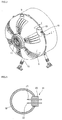
- Fig. 2 is a perspective view of a backside of a tub in a washing machine of the present invention
- Fig. 3 is a sectional view taken along a line I-I' of Fig. 2;
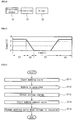
- Fig. 4 is a control block diagram associated with an electrode sensor
- Fig. 5 is a view of a voltage change detected by an electrode sensor
- Fig. 6 is a flowchart of a method of removing a bubble in a washing machine according to the present invention.
- Fig. 7 is a view of the second embodiment according to the present invention.
- Fig. 8 is a view of the third embodiment according to the present invention.
- Fig. 1 is a sectional view of a washing machine of the present invention.
- the drum washing machine includes: an outcase 20; a tub 6 received in the outcase 20; a drum 7 rotating inside the tub 6; a motor 11 disposed at a rear side of the drum 7; and a driving shaft 12 connected with the motor 11 and the drum 7, for providing a driving force.
- the drum washing machine further includes: a water hose 1 through which washing water is supplied from the outside; a detergent insertion member 2 to which the water from the water hose 1 is supplied and detergent received therein is molten and properly supplied; and an insertion pipe 3 connected between the detergent insertion member 2 and the tub 6, for supplying water mixed with the detergent to the tub 6.
- the insertion pipe 3 includes: a 'U'-shaped pipe 4 bent vertically so that air or water may not flow backward from the tub 6; a bellows 5 for preventing vibration of the tub 6 from propagating to the outcase 20; and a water pipe 19 disposed in a connection portion between the bellows 5 and the tub 6.
- the water pipe 19 has an electrode sensor 10 therein so that when a bubble rises along the water pipe 19, the electrode sensor 10 is conducted by conductivity of the bubble itself and thus bubble generation can be detected.
- a detection signal is transferred to a controller of the washing machine, so that the bubble-removal cycle is performed in a predetermined process.
- the drain unit includes: a drain pipe 16 for guiding the water of the tub 6; a drain pump 17 for forcibly discharging the water from the drain pipe 16; and a drain hose 18 for allowing the water to be connected with the outside of the washing machine.
- the tub 6 has a communication pipe 9 formed in an upper side thereof and through which the inner space of the tub 6 communicates with the outside of the tub 6 to allow outside air may flow in freely, and to prevent a child from being choked when the child might enter the inside of the tub 6.
- a door 13 is formed on a front side of the tub 6 to open and close the inside of the tub 6 and receive the laundry.
- a manipulation unit 13 with which a user performs a manipulation is formed on an upper side of the door 13.
- a damper 15 supports the weight of the tub 6 and attenuates vibration produced during rotation of the drum 7.
- the drum 7 has a plurality of holes 8 formed in an outer periphery thereof to allow the washing water to flow in and out to and from the inside of the drum 7.
- the washing water is supplied through the water hose 1 and the insertion pipe 3 first.
- the water can selectively pass through the detergent insertion member 2 so that the water can be mixed with the detergent.
- the drum 7 is rotated by the motor 11, so that the washing cycle is performed.
- the laundry received in the drum 7 is washed by frictional force produced when the laundry collides with the washing water while the laundry falls down in the drum.
- the water in the tub 6 is forcibly sucked by the dram pump 17 and drained to the outside.
- bubbles can be generated due to the collision between the laundry and the washing water.
- the bubbles are constantly produced within the tub 6 and rise along the inner space of the tub 6. When the bubbles rise, they hinder the falling operation of the laundry, so that washing efficiency may deteriorate.
- the bubbles have the electrode sensor 10 formed in the water pipe 19 conduct to each other. When excessive generation of the bubbles is detected by the conduction of the electrode sensor 10, the bubble-removal cycle for reducing the bubble is performed by suspending the washing cycle or supplying the washing water additionally.
- Fig. 2 is a perspective view of a backside of a tub in a washing machine of the present invention.
- the weight of the tub 6 can be supported by a plurality of damper 15 and the motor 11 is installed at the back of the tub 6 so that rotational force can be transferred to the side of the drum 7. Since the motor 11 is directly connected with the back of the tub 6, vibration noise and friction loss are also reduced.
- the communication pipe 9 is formed on the upper end of the tub 6 so that outside air can flow into the tub 6 and inside air can be discharged to the outside. Therefore, the communication pipe 9 can prevent a child from being choked to death when the child enters the inside of the tub 6.
- the water pipe 19 is formed at a position lower than the communication pipe 9 in the outer periphery of the tub 6. The water mixed with the detergent and pure water is supplied through the water pipe 19.
- the electrode sensor 10 is formed in the inside of the water pipe 19 as one characteristic of the present invention.
- the bubble generation can be detected by the electrode sensor 10.
- Forming the electrode sensor 10 in the inside of the water pipe 19 is intended for preventing collision with the laundry to stably mount the electrode sensor 10 and more swiftly detecting the bubble generation to allow the washing machine to start the bubble-removal cycle swiftly. If the electrode sensor 10 is formed at an arbitrary position on the inner surface of tub 6, the installation position of the electrode sensor 10 cannot be maintained stably due to collision with the washing water. Also, if the electrode sensor 10 is formed in the inside of the communication pipe 9, the bubble-removal cycle cannot be properly performed.
- the communication pipe 9 is formed at a lower position of an entire height of the tub 6, the electrode sensor 10 may be formed in the inside of the communication pipe 9. At this point, the communication pipe 9 should be formed at a height such that the water in the tub 6 does not flow backward through the communication pipe 9.
- the electrode sensor 10 can be formed at a pipe formed as a predetermined pipe shape and communicating with the tub 6, and formed at a height such that the washing water is not leaked during the washing cycle.
- the pipe for performing such a function can include the communication pipe 9 and the water pipe 19 provided to a general washing machine.
- the electrode sensor 10 can be also formed in a condensing duct in the case of a condensing type washing machine having a dry function and formed in an exhaust port in the case of an exhaust-type washing machine having a dry function depending on the types of the washing machine.
- Fig. 3 is a sectional view taken along a line I-I' of Fig. 2.
- the electrode sensor 10 is formed in the inside of the water pipe 19.
- the electrode sensor 10 includes: the first electrode 21 and the second electrode 22 projected into the inside of the water pipe 19 and contacting the inner environment of the water pipe 19; and an insulator 23 fit in the water pipe 10, for allowing the position of the electrode sensor 10 to fixed therein and the electrodes 21 and 22 to be insulated to each other.
- the insulator further performs as a sealer for preventing the water or the bubble flowing in the water pipe 19 from leaking out to the outside.
- other type sealing member for performing the sealing function may be further formed.
- the electrodes 21 and 22 are horizontally formed at the same height, so that the bubbles may contact the first and second electrodes 21 and 22 simultaneously when the bubbles rise along the water pipe 19.
- the bubbles can be detected only if the other electrode contacts the bubbles after one electrode contacts the bubbles, so that a time the bubbles are detected is delayed as much as that.
- Fig. 4 is a control block diagram associated with an electrode sensor and Fig. 5 is a view of a voltage change detected by an electrode sensor.
- Figs. 4 and 5 when the bubbles contact the electrode sensor 10, electricity flows between a pair of electrodes 21 and 22 by ion from the detergent contained in the bubbles and conductive ion of the washing water itself.
- the electrode sensor 10 is conducted, a detection signal is transferred to the controller 31 of the washing machine.
- the controller 31 controls the driver 32 of the washing machine to allow the bubble-removal cycle to be performed.
- a water supply unit including the water hose is controlled to supply cool water or the drivr including the motor is controlled to suspense rotation of the drum 7.
- a voltage change of the electrode sensor 10 detected while the bubbles contact the electrode sensor 10 will be descried in detail with reference to Fig. 5.
- a voltage of about 5 volt is formed between two ends of the electrode sensor (refer to a region D1).
- a current flows between the electrodes 21 and 22 through the bubbles from the point when the bubbles fill the inside of the tub 6, rise along the water pipe 19, and contact the electrode sensor 10, the voltage gradually drops down (refer to a region D2). From that point, the washing machine performs the bubble-removal cycle.
- the bubbles contacting the electrodes 21 and 22 is also removed, so that the voltage formed between the two electrodes 21 and 22 is gradually raised (refer to a region D3).
- the washing machine resumes the state of before the bubble-removal cycle has been performed, and continues to perform the washing cycle (refer to a region D4).
- Fig. 6 is a flowchart of a method of removing a bubble in a washing machine according to the present invention.
- the washing cycle starts (st 11)
- the bubbles are generated by collision between the laundry and the washing water.
- the detergent is excessively inserted
- the bubbles are accumulated more and more in the inside of the tub 6 and resultantly rise along the water pipe 19 (st 12).
- the bubbles rising along the water pipe 19 contain ion produced when the detergent is molted in the washing water and ion from the washing water itself and thus form electrolyte. Therefore, when such bubbles contact the electrodes 21 and 22, the electrode sensor is conducted and the voltage drastically drops because there is no resistance between the electrodes 21 and 22 (st 13).
- the washing machine starts the bubble-removal cycle to remove the bubbles in the inside of the tub 6 (st 14). After the bubbles are removed by the bubble-removal cycle, the voltage applied between the electrodes 21 and 22 is recovered to the original voltage. After the voltage is recovered, the washing cycle that has been performed resumes (st 15).
- the electrode sensor 10 As described above, when the bubbles, which is electrolyte, contact the electrode sensor 10 installed in the inside of the water pipe 19, the electrode sensor 10 is conducted. After the bubble generation is detected by conduction of the electrode sensor 10, the driver of the washing machine is controlled to allow the bubble-removal cycle of the washing machine to be performed. After the bubbles are removed, the voltage applied between the both ends of the electrode sensor 10 is recovered. When the voltage is recovered, it is recognized that the bubbles have been removed and the washing machine can resume the previous cycle it has performed.
- the bubble-removal method is performed by an electronic-sensitive method that uses a property that electricity is conducted by ion contained much in the bubbles, operation reliability can be enhanced.
- Fig. 7 is a view of the second embodiment according to the present invention.
- the electrodes 21 and 22 are a bar type and protruded in a predetermined length in the inside of the water pipe 19.
- the bar type electrodes can be stained with foreign substance, so that electricity may not be conducted between the stained electrodes.
- the second embodiment adopts plate-shaped electrodes 24 and 25 having a plate whose contact area is wide, so that the electrodes may be formed over the wide inner wall of the water pipe 19.
- Fig. 8 is a view of the third embodiment according to the present invention. The third embodiment will be described with reference to Fig. 8.
- the wall of the water pipe 19 is punched and the electrode sensor is fit and fixed therein.
- a manufacturing process requires additional process of punching the water pipe 19.
- a plurality of bending portions 28 and 29 are formed in parts extending from the plate-shaped electrodes 26 and 27 so that the electrode sensor 10 may be fixed in the water pipe 19.
- one bending surface forms a stand 28 hooked at the upper end of the water pipe 19 and the surface extending further forms a guide 29 in which the electrode 26 can be inserted.
- the electrodes 26 and 27 are hooked in the inner surface of the water pipe 19 by a user.
- the guide 29 is pulled at the outside of the water pipe 19 to pull the electrode.
- the stand 28 is hooked at the upper end of the water pipe 19, the pulling operation is stopped. If the pulling operation is finished, force grasping the water pipe 19 is produced due to mutual pull force between the guide 29 and the electrode 26, so that the mutual positions of the electrode sensor 10 and the water pipe 19 can be fixed.
- the bellows 5 is fixed thereon, so that the electrode sensor 10 can be firmly fixed.
- the process of installing the electrode sensor 10 and the process of manufacturing the water pipe 19 can be performed in a simpler and more convenient manner. Since the parts not described in the third embodiment have been clearly described in the first and second embodiments, descriptions thereof will be omitted.
- the bubble generation can be reliably detected.
- the reliability of the electrode sensor 10 may be deteriorated.
- the sprint of the present invention can be properly realized even though the electrode sensor is directly installed in the inner periphery of the tub.
- the present invention it is possible to enhance the washing efficiency by detecting the bubble as soon as the bubble is generated during the washing cycle and immediately performing the bubble-removal cycle.
- the present invention can be applied to the open type washing machine where the inner/outer sides of the tub are open, applicability of the bubble detection device can be increased.
- the bubble generation can be detected by the electronic-sensitive method that uses the conductivity in the inside of the bubbles, the operational reliability of the bubble detection device can be improved.
Landscapes
- Engineering & Computer Science (AREA)
- Textile Engineering (AREA)
- Control Of Washing Machine And Dryer (AREA)
- Detail Structures Of Washing Machines And Dryers (AREA)
Applications Claiming Priority (1)
| Application Number | Priority Date | Filing Date | Title |
|---|---|---|---|
| KR1020040089442A KR20060040199A (ko) | 2004-11-04 | 2004-11-04 | 세탁기의 거품감지장치 및 거품감지방법 |
Publications (1)
| Publication Number | Publication Date |
|---|---|
| EP1655407A1 true EP1655407A1 (fr) | 2006-05-10 |
Family
ID=34942419
Family Applications (1)
| Application Number | Title | Priority Date | Filing Date |
|---|---|---|---|
| EP05291296A Withdrawn EP1655407A1 (fr) | 2004-11-04 | 2005-06-16 | Machine à laver, dispositif et procédé pour régler celle-ci |
Country Status (5)
| Country | Link |
|---|---|
| US (1) | US20060090268A1 (fr) |
| EP (1) | EP1655407A1 (fr) |
| KR (1) | KR20060040199A (fr) |
| CN (1) | CN1769574A (fr) |
| AU (1) | AU2005203224A1 (fr) |
Cited By (2)
| Publication number | Priority date | Publication date | Assignee | Title |
|---|---|---|---|---|
| EP2133455A1 (fr) * | 2008-06-12 | 2009-12-16 | BSH Bosch und Siemens Hausgeräte GmbH | Procédé et dispositif de détermination de mousse dans un lave-linge |
| EP2889421A1 (fr) * | 2013-12-26 | 2015-07-01 | Dongbu Daewoo Electronics Corporation | Machine à laver à tambour et son procédé de fonctionnement |
Families Citing this family (14)
| Publication number | Priority date | Publication date | Assignee | Title |
|---|---|---|---|---|
| DE102006060256A1 (de) * | 2006-12-14 | 2008-06-26 | E.G.O. Elektro-Gerätebau GmbH | Verfahren zur Steuerung einer Waschmaschine |
| KR101526968B1 (ko) * | 2008-04-30 | 2015-06-11 | 엘지전자 주식회사 | 드럼 세탁기 및 그 제어방법 |
| EP2716806A4 (fr) * | 2011-05-31 | 2015-01-21 | Lg Electronics Inc | Dispositif de lavage |
| WO2013001681A1 (fr) * | 2011-06-29 | 2013-01-03 | パナソニック株式会社 | Machine à laver à tambour |
| CN104695167B (zh) * | 2013-12-04 | 2018-09-25 | 博西华电器(江苏)有限公司 | 洗衣机中的泡沫消除方法及洗衣机 |
| CN104695176A (zh) * | 2013-12-04 | 2015-06-10 | 博西华电器(江苏)有限公司 | 洗衣机中的泡沫检测方法及洗衣机 |
| JP7009816B2 (ja) * | 2017-07-27 | 2022-02-10 | 青島海爾洗衣机有限公司 | 靴洗浄装置 |
| CN109468798A (zh) * | 2017-09-08 | 2019-03-15 | 青岛海尔滚筒洗衣机有限公司 | 用于衣物处理设备的消泡方法和衣物处理设备 |
| KR102633155B1 (ko) | 2019-04-15 | 2024-02-05 | 엘지전자 주식회사 | 의류 처리 장치 및 그 제어방법 |
| CN111926539B (zh) * | 2019-04-26 | 2023-02-21 | 无锡小天鹅电器有限公司 | 衣物处理装置、泡沫处理方法、装置及可读存储介质 |
| CN111856587A (zh) * | 2019-04-26 | 2020-10-30 | 无锡小天鹅电器有限公司 | 泡沫感知装置、衣物处理装置及感知方法 |
| CN111926537B (zh) * | 2019-04-26 | 2022-03-18 | 无锡小天鹅电器有限公司 | 衣物处理装置、泡沫处理方法、装置及可读存储介质 |
| CN112095298A (zh) * | 2019-06-18 | 2020-12-18 | 青岛海尔滚筒洗衣机有限公司 | 一种气压平衡装置、洗衣机及洗衣机的控制方法 |
| CN120700685A (zh) * | 2024-08-08 | 2025-09-26 | 小米科技(武汉)有限公司 | 洗衣机进水系统及洗衣机 |
Citations (4)
| Publication number | Priority date | Publication date | Assignee | Title |
|---|---|---|---|---|
| JPH04246400A (ja) * | 1991-02-01 | 1992-09-02 | Sharp Corp | ドラム式洗濯機 |
| GB2266898A (en) * | 1992-05-09 | 1993-11-17 | Hotpoint Ltd | Rinsing in washing machines |
| DE19821148A1 (de) * | 1998-05-12 | 1999-11-18 | Aeg Hausgeraete Gmbh | Programmgesteuertes wasserführendes elektrisches Haushaltsgerät |
| JP2003260290A (ja) * | 2002-03-07 | 2003-09-16 | Sanyo Electric Co Ltd | ドラム式洗濯機 |
Family Cites Families (5)
| Publication number | Priority date | Publication date | Assignee | Title |
|---|---|---|---|---|
| US4510778A (en) * | 1983-12-27 | 1985-04-16 | The Maytag Company | Control system for a combined appliance |
| US7000436B2 (en) * | 2001-08-06 | 2006-02-21 | Emerson Electric Co. | Appliance control system with hyperspin mode |
| KR100487342B1 (ko) * | 2002-11-26 | 2005-05-03 | 엘지전자 주식회사 | 세탁기 |
| KR100775831B1 (ko) * | 2005-06-08 | 2007-11-13 | 엘지전자 주식회사 | 드럼세탁기의 거품감지장치 및 이를 구비하는 드럼세탁기 |
| KR101253181B1 (ko) * | 2006-12-26 | 2013-04-10 | 엘지전자 주식회사 | 건조기 및 그 제어방법 |
-
2004
- 2004-11-04 KR KR1020040089442A patent/KR20060040199A/ko not_active Ceased
-
2005
- 2005-06-16 EP EP05291296A patent/EP1655407A1/fr not_active Withdrawn
- 2005-07-13 US US11/181,623 patent/US20060090268A1/en not_active Abandoned
- 2005-07-14 CN CNA2005100833834A patent/CN1769574A/zh active Pending
- 2005-07-15 AU AU2005203224A patent/AU2005203224A1/en not_active Abandoned
Patent Citations (4)
| Publication number | Priority date | Publication date | Assignee | Title |
|---|---|---|---|---|
| JPH04246400A (ja) * | 1991-02-01 | 1992-09-02 | Sharp Corp | ドラム式洗濯機 |
| GB2266898A (en) * | 1992-05-09 | 1993-11-17 | Hotpoint Ltd | Rinsing in washing machines |
| DE19821148A1 (de) * | 1998-05-12 | 1999-11-18 | Aeg Hausgeraete Gmbh | Programmgesteuertes wasserführendes elektrisches Haushaltsgerät |
| JP2003260290A (ja) * | 2002-03-07 | 2003-09-16 | Sanyo Electric Co Ltd | ドラム式洗濯機 |
Non-Patent Citations (2)
| Title |
|---|
| PATENT ABSTRACTS OF JAPAN vol. 017, no. 025 (C - 1017) 18 January 1993 (1993-01-18) * |
| PATENT ABSTRACTS OF JAPAN vol. 2003, no. 12 5 December 2003 (2003-12-05) * |
Cited By (3)
| Publication number | Priority date | Publication date | Assignee | Title |
|---|---|---|---|---|
| EP2133455A1 (fr) * | 2008-06-12 | 2009-12-16 | BSH Bosch und Siemens Hausgeräte GmbH | Procédé et dispositif de détermination de mousse dans un lave-linge |
| EP2889421A1 (fr) * | 2013-12-26 | 2015-07-01 | Dongbu Daewoo Electronics Corporation | Machine à laver à tambour et son procédé de fonctionnement |
| US9809915B2 (en) | 2013-12-26 | 2017-11-07 | Dongbu Daewoo Electronics Corporation | Drum type washing machine and operating method of the same |
Also Published As
| Publication number | Publication date |
|---|---|
| CN1769574A (zh) | 2006-05-10 |
| AU2005203224A1 (en) | 2006-05-18 |
| US20060090268A1 (en) | 2006-05-04 |
| KR20060040199A (ko) | 2006-05-10 |
Similar Documents
| Publication | Publication Date | Title |
|---|---|---|
| US20060090268A1 (en) | Washing machine, apparatus and method of controlling the same | |
| US10934658B2 (en) | Laundry treating apparatus and method for supplying washing agent thereof | |
| EP3385436A1 (fr) | Procédé de drainage d'eau de machine à laver | |
| AU2010249192B2 (en) | Washing machine and washing method | |
| CN101994236B (zh) | 洗衣机 | |
| WO2006129916A1 (fr) | Machine a laver le linge | |
| CN110965278A (zh) | 洗衣机 | |
| WO2016068574A1 (fr) | Machine à laver | |
| EP2889421B1 (fr) | Machine à laver à tambour et son procédé de fonctionnement | |
| JP4600221B2 (ja) | ドラム式洗濯機 | |
| EP3365487B1 (fr) | Machine à laver | |
| CN1609330B (zh) | 洗衣机 | |
| BRPI0604754B1 (pt) | método para lavar uma carga de lavagem de tecido em um aparelho de lavagem | |
| BR102016022920A2 (pt) | Método para controlar uma máquina de lavar e máquina de lavar | |
| CN103443347A (zh) | 操作洗衣机或洗衣干衣机的方法及对应的洗衣机或洗衣干衣机 | |
| CN112424412B (zh) | 洗衣机 | |
| JP2015054108A (ja) | 洗濯機 | |
| JP2021049215A (ja) | ドラム式洗濯機 | |
| JP2007202638A (ja) | ドラム式洗濯機 | |
| CN110741118A (zh) | 衣物处理设备及其控制方法 | |
| JP3046487B2 (ja) | 脱水洗濯機 | |
| JP2014042741A (ja) | 洗濯乾燥機 | |
| JP2022159586A (ja) | 洗濯機 | |
| KR20080014132A (ko) | 스팀발생장치 및 이를 이용한 세탁기 | |
| JP2005013577A (ja) | ドラム式洗濯機 |
Legal Events
| Date | Code | Title | Description |
|---|---|---|---|
| PUAI | Public reference made under article 153(3) epc to a published international application that has entered the european phase |
Free format text: ORIGINAL CODE: 0009012 |
|
| AK | Designated contracting states |
Kind code of ref document: A1 Designated state(s): AT BE BG CH CY CZ DE DK EE ES FI FR GB GR HU IE IS IT LI LT LU MC NL PL PT RO SE SI SK TR |
|
| AX | Request for extension of the european patent |
Extension state: AL BA HR LV MK YU |
|
| 17P | Request for examination filed |
Effective date: 20060907 |
|
| 17Q | First examination report despatched |
Effective date: 20061016 |
|
| AKX | Designation fees paid |
Designated state(s): DE FR GB |
|
| STAA | Information on the status of an ep patent application or granted ep patent |
Free format text: STATUS: THE APPLICATION IS DEEMED TO BE WITHDRAWN |
|
| 18D | Application deemed to be withdrawn |
Effective date: 20070427 |