EP1655448A2 - Verbinder von Abstandshalterprofilleisten zwischen Isolierglasscheiben - Google Patents
Verbinder von Abstandshalterprofilleisten zwischen Isolierglasscheiben Download PDFInfo
- Publication number
- EP1655448A2 EP1655448A2 EP05004645A EP05004645A EP1655448A2 EP 1655448 A2 EP1655448 A2 EP 1655448A2 EP 05004645 A EP05004645 A EP 05004645A EP 05004645 A EP05004645 A EP 05004645A EP 1655448 A2 EP1655448 A2 EP 1655448A2
- Authority
- EP
- European Patent Office
- Prior art keywords
- connector
- plug
- hollow profile
- connector according
- flaps
- Prior art date
- Legal status (The legal status is an assumption and is not a legal conclusion. Google has not performed a legal analysis and makes no representation as to the accuracy of the status listed.)
- Granted
Links
Images


Classifications
-
- E—FIXED CONSTRUCTIONS
- E06—DOORS, WINDOWS, SHUTTERS, OR ROLLER BLINDS IN GENERAL; LADDERS
- E06B—FIXED OR MOVABLE CLOSURES FOR OPENINGS IN BUILDINGS, VEHICLES, FENCES OR LIKE ENCLOSURES IN GENERAL, e.g. DOORS, WINDOWS, BLINDS, GATES
- E06B3/00—Window sashes, door leaves, or like elements for closing wall or like openings; Layout of fixed or moving closures, e.g. windows in wall or like openings; Features of rigidly-mounted outer frames relating to the mounting of wing frames
- E06B3/66—Units comprising two or more parallel glass or like panes permanently secured together
- E06B3/663—Elements for spacing panes
- E06B3/667—Connectors therefor
Definitions
- the invention relates to a plug-in connector, which is a linear or corner connector made of plastic and / or metal, for sections of a hollow profile strip for spacing of insulating glass panes, wherein a Thiokol seal is introduced to the outer edge of the insulating glass panes around the hollow profile strip and wherein the male connector an outer profile has, which corresponds substantially to the inner profile of the hollow profile strips.
- Arrangements of plug-in connectors in hollow spacer profile strips between insulating glass panes are known from DE 195 27 930.
- the male connector has a U- or hollow profile, and the outer surface are provided with ribs or the like, so that a good interference fit is ensured in the hollow profile strips and these do not pull apart on thermal length changes on the connector.
- the glass sheets are attached to the spacer frame with a Thiokol adhesive. However, this is permeable to gas, so that the outer edges of the Hohlprofilverklebung be sealed with a Butylkitt to prevent ingress of moisture in the glass interior and an exit of the high molecular weight gas filling.
- a tightness of the joints of a plug-in connector coupled to each other hollow profile strips, however, is not given, and it requires complex single-sealing measures of the joints.
- the plug-in connector is solid or has a U-shape with the hollow profile strips adapted inside hollow profile shape and carries retaining lamellae, which provide a backing against removal of the hollow profile strips, which, however, is particularly effective only in limited critical shock-sealing area. Dry filler gas can escape from the disk via the abutting area of the spacer ends, and moist air can diffuse through the Thiokol bonding of the disks with the spacers into the interior of the disk, which greatly reduces their insulating function.
- corner connectors from the P 42 35 397 C1 are known, are pushed onto the legs of hollow-profile spacers, each ending at a stepped shoulder of the corner connector, where, however, no secure seal to the interior of the laminated glass arises.
- the male connector on the side facing the Thiokol seal on a central or corner longitudinal region has a shallow depression, at both ends of each mirror image a thin flap is hinged and / or hinged, which is obliquely filled with Butylkitt underfilled and pivoted with deferred hollow profile strip in the recess, this approximately fills, wherein edge of the flaps exiting Butylkitt seals a joint area at the free ends.
- the recess is arranged in an upper surface in the middle of the male connector or adjacent to the stepped heels of the corner connector.
- the push area in the connector center or at the corner of the exiting Butylkitt be achieved when inserting into the hollow profile strips and securely sealed the joint.
- the flaps are flexibly hinged, in particular with a film hinge easily movable in each case attached to the edge of the recess facing the end of the male connector.
- the male connector is so injected that the flaps are initially inclined and the recess is exposed.
- Butylkitt in the recess is such that by inserting the connector in the hollow profile strips and thus pressing down the flaps so much butyl putty exits the recess that the distance between the two hollow profile strips or corner connector stepped paragraph filled with butyl putty safely becomes.
- the position of the male connector between the hollow profile strips is determined by stop webs or the corner piece.
- a stop ridge is located on the bottom surface of the male connector, opposite the gap between the two flaps. Further stop webs are advantageously located on each side of the male connector in the middle on the respective slope of the U-shaped connector.
- the plug-in connector to the edge regions on both sides of the recess or the corner piece in a row slide anti-slip webs and / or nubs, which consist of softer plastic, as the remaining male connector, and which fit with a press fit into the inner profile of the hollow profile strip.
- a further improvement of the seal which is also to be used in combination with the above, is that the flaps are provided with transverse slots, from which the Butylkitt exiting a bond to the respectively deferred there hollow profile strip produced on the inside.
- a third improvement of the seal which is also to be used in combination with one or both of the above, is that the connector has a hollow profile, in whose low side walls in each case a metal strip is mounted injected.
- the metal strip can also undergo U-shaped bottom side.
- the flaps are easily movably attached to the edge of the recess with a film hinge facing the end of the male connector.
- the male connector is sprayed so thin on the folding joints, that the flaps are movable over the recess.
- the plastic of the connector is preferably glass fiber doped so that it has low shrinkage and relatively high stability but limited elasticity. Therefore, only a moderate retention by the basic structure of the connector surfaces, even if it is corrugated, given unfavorable tolerance ratios of the connector and strip cross-section. This offer the anti-slip bars remedy.
- These anti-slip webs are placed in the edge region on both sides in front of and behind the recess perpendicular to the connector surface and have z. B. a height of about 5 mm, a small thickness of at most one millimeter and a height excess to Cross-sectional profile of 0.1 to 0.3 mm.
- These clamping webs are each elastically supported to the nearest end of the connector with a soft plastic, wherein the height of the support decreases with the distance from the clamping web. For example, five clamping webs are formed on each of the four edge regions.
- the one-sided soft plastic support parts give the supports sufficient elasticity when sliding the profile strips and a firm hold against pulling out, the excess of the narrow hard web penetrates when inserted into the profile strip and then partially bulge.
- anti-slip bars are slip-resistant nubs, which are also applied to the edge areas. They are designed as truncated pyramids of soft plastic and each rise from the cross-section of the hollow profile strip closely tolerated edge region by an excess of 0.3 mm to 0.6 mm in the entire cross section.
- the length of the truncated pyramids in the direction of insertion of the connector at the base is about 5 mm, its width about 2 mm and its plateau length about 1 mm.
- transverse slots in the flaps.
- These slots have z. B. a width of 1 - 2 mm and each extend over about 80% of the flap width.
- the male connectors are preferably provided with relatively thick side walls, so that the clamping webs and the clamping knobs are fully supported by them. Also, the bottom wall, which is directed to the interior of the insulating glass pane and connects the side walls over its entire length, is stable and relatively thick, z. B. 1 mm thick, formed.
- Another alternative is to use an elastic, low-doped plastic for the connector and to stabilize the side walls and / or the bottom respectively by inserted thin metal bands, so that also stable connectors for smallest hollow profile dimensions are to be produced.
- Sidewall corrugation with low cross-sectional excess is provided.
- the metal bands are preferably L-shaped angled or corrugated in the longitudinal direction.
- the short L-bar has about a length corresponding to the material thickness, which is about 0.3 - 0.6 mm.
- the short L-legs are directed to the bottom plate of the connector.
- the male connector is an angle-shaped corner connector and has a solid corner body whose outer contour corresponds approximately to the contour of the hollow profile strip, in which extending from the corner body stepped with a Einsteckarme, which have outwardly directed recesses on whose end edges, the flaps are hinged with film hinges whose free ends close to the level, so that the butyl putty located under the flap of the sealing emerges.
- the flaps and the connector are each tapered end.
- the connector is advantageously formed with retaining lamellae or in the manner of the above-described restraints, wherein the insertion arms are supported under the edge groves and on the opposite strip side.
- the corner body forms a step to the Einsteckarmen, so that thereby the hollow profile strip ends abut sealingly there and the granules can not pass through the gap.
- FIG. 9 shows an edge region of an insulating glass pane consisting of two glass panes 10A, 10B, which are held spaced apart by spacer hollow profile strips 8A, 8B with the interposition of a thin butyl putty strip 24.
- an axially continuous plug-in connector made of plastic is introduced, of which only a narrow centering stop bar 5 behind the cut ButylkittstMail and from the connector, the joint area 11th the profile strips leaked, sealing Butylkitt 9 can be seen.
- the hollow profile strips 8A, 8B and the plug-in connector are axially permeable and filled with a powdery absorber means A.
- the inner space 22 between the panes of glass is usually filled with a heavy gas trapped by the sealant 20 introduced into the peripheral area between the panes of glass exteriorly adjacent to the spacers 8A, 8B, only a portion of which is shown in the figure.
- the spacer profile has directed to the seal 20 sloping grooves 23 at the edges, whereby the seal is increased.
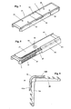
- Figure 1 shows a side view of a male connector 1 prior to installation in a first embodiment.
- the side wall 16 and the bottom 26 are continuous and have centrally a narrow stop web 5, to which the hollow profile strips are pushed from both sides.
- each side ribs 7 are formed profiled.
- the corresponding edge regions of the side walls 16 are each provided with a groove 25.
- the side walls 16 are lowered in each case on both Einsteck Schemeen and occupied with narrow anti-slip webs 12.
- each of softer plastic material web buffer 12 A are introduced, each of which is directed to the connector ends fall off.
- the anti-slip webs 12 protrude beyond the outer profile of the groove 25 and the connector outer side - in the picture above - slightly, so that inserted pushed a press fit to the clear profile of the hollow profile strip.
- a recess 2 In the central connector longitudinal area is a recess 2, which is filled with an excess of butyl putty 9.
- each flaps 3A, 3B are articulated with a film hinge 4.
- Figure 2 shows an end view of the male connector 1, which makes the fairly thick side walls 16, 17 and the continuous bottom 26 clearly.
- FIG. 3 shows a perspective view of the connector 1 according to FIGS. 1 and 2 from the side facing the edge of the pane.
- bridges 27 extend parallel to the bottom 26.
- cover plate 28 containing the shallow recess 2 facing outside, at both ends of which the flaps 3A , 3B hinged to each other and in which the Butylkitt 9 is included in abundance, so that the flap 3A, 3B are slightly pressed upwards inclined before they are inserted into the hollow profile.
- the flaps are each formed in transverse slots 14, 15, so that at a fixed pressing the flaps 3A, 3B to a parallel position to the cover plate 28 of butyl putty 9 from these and from the remaining between the free flap ends gap and to the Side edges emerges and connects to a respective deferred inner wall of the hollow profile strip and glued.
- the spacer strips can be caulked into the slots, providing additional sealing and security against separation. Recesses 80 from caulking are shown on the hollow profile in FIG.
- the lower level of the anti-slip nubble 13 is slightly below the upper edge of the edges of the side walls 16, 17, and the upper plateau of the nubs protrudes by a few tenths of a millimeter in the clear profile of the hollow profile strips 8 B, so that they each show a slight buckling 29 show, thus a very strong hold against retraction arises.
- Figures 4 and 5 show an alternative embodiment of the connector 1 is enlarged, wherein in the perspective view a hollow profile section 8B is partially pushed.
- skid-resistant nubs 13 are molded of soft plastic in this embodiment in addition to the grooves. These nubs 13 are wedge or formed truncated pyramid. They fall to the connector ends each flatter than on the opposite side.
- Figures 6 to 8 show a third embodiment of the male connector 1, wherein the Butylkitt is not yet introduced into the recess 2 and the flaps 3A, 3B still project obliquely.
- Significant difference from the above-described embodiments is the exact fit, in particular of the bottom 26 and the flutes 25 in the clear profile of the hollow profile strips and the dimensional stability of the side walls 16, 17 each containing a steel insert 18, 19, such as the double-enlarged cross-section AA, such as Figure 6 shows.
- the sheet thickness corresponds in the example about a quarter of the side wall thickness. In the bottom region, the metal strip 16, 17 is angled parallel to the bottom 26. The short leg length corresponds approximately to the strip thickness.
- the sheet metal insert also makes it possible to produce very thin, stable side walls which, with small connector cross-sections, leave sufficient space for flow of absorber powder.
- Figure 8 shows the plug-in connector 1 with a plugged up to the stop 5 hollow profile strip 8B and not yet fully pushed bar 8A.
- the flap 3A is already folded down, so that the Butylkitt 9 has leaked into the gap in the joint area and seals it.
- Figure 10 shows a side view of the corner connector 1A as it comes from the injection mold.
- the usually massive corner body 30 which is formed substantially as a cylinder quadrant, extend at right angles to each other two Einsteckarme 31, 32 from the radial surfaces.
- Radially outwardly offset are shorter and thinner flaps 3A, 3B hinged with film hinges at the edges of the quadrant, so that they can be pivoted in each case in the direction of the recess in the outer wall 28 of the adjacent Einsteckarme 31, 32.
- flaps 3A, 3B hinged with film hinges at the edges of the quadrant, so that they can be pivoted in each case in the direction of the recess in the outer wall 28 of the adjacent Einsteckarme 31, 32.
- the Einsteckarme 31, 32 protrude in their longitudinal extent beyond the flaps 3A, 3B and are provided in the protruding areas with retaining louvers 35, 36, which provide a tight fit in the spacer profile.
- the lamellae 35, 36 project beyond the outer walls 28.
- Figure 11 shows a plan view of Figure 10. It can be seen that the Einsteckarme 31, and the flaps 3A, 3B carry at their ends guide slopes.
- the profiles of the corner body 30, the Einsteckarme 31 and the retaining louvers 35 are throaty formed so that they fit to a conventional spacer profile inside or outside.
- the corner body 30 protrudes on all sides with a step 37 beyond the Einsteckarme 31, so that there is a tight stop for the spacer profile is formed. In the local gap sealing the excess of Butylkitt is squeezed, which is introduced under the flap 3A, 3B respectively.
- FIG. 12 shows a variant of a corner connector.
- the flaps 3A, 3B each insertion side of the recess 2 of the Einsteckarme 31, 32 hinged, and the free flap ends reach close to the level 37, 38 which limits the corner body 30.
- the flaps 3A, 3B lie down when pushing the hollow sections over the recess 2 and squeeze Butylkitt in the shock at the stage.
- the one hollow profile end 8 B is shown partially pushed onto the Einsteckarm 32.
Landscapes
- Engineering & Computer Science (AREA)
- Civil Engineering (AREA)
- Structural Engineering (AREA)
- Building Environments (AREA)
- Buffer Packaging (AREA)
- Insulating Bodies (AREA)
Abstract
Description
- Die Erfindung betrifft einen Einsteckverbinder, der ein Linear-oder Eckverbinder aus Kunststoff und/oder Metall ist, für Abschnitte einer Hohlprofilleiste zur Abstandshaltung von Isolierglasscheiben, wobei um die Hohlprofilleiste eine Thiokol-Abdichtung zum Außenrand der Isolierglasscheiben gerichtet eingebracht ist und wobei der Einsteckverbinder ein Außenprofil aufweist, das im wesentlichen dem Innenprofil der Hohlprofilleisten entspricht.
- Anordnungen von Einsteckverbindern in hohlen Abstandshalteprofilleisten zwischen Isolierglasscheiben sind aus der DE 195 27 930 bekannt. Der Einsteckverbinder weist ein U- oder Hohlprofil auf, und die Außenfläche sind mit Rippen oder dergleichen versehen, so daß ein guter Presssitz in den Hohlprofilleisten gewährleistet ist und diese sich bei thermischen Längenveränderungen nicht über den Verbinder auseinanderziehen. Die Glasscheiben werden auf dem Abstandshalterrahmen mit einem Thiokolkleber befestigt. Dieser ist jedoch gasdurchlässig, so daß zur Verhinderung eines Feuchtigkeitseintritts in den Glasscheibeninnenraum und eines Austritts des hochmolekularen Füllgases die äußeren Ränder der Hohlprofilverklebung mit einem Butylkitt abgedichtet werden. Eine Dichtigkeit der Stoßstellen der mit einem Einsteckverbinder aneinander gekoppelten Hohlprofilleisten ist jedoch dadurch nicht gegeben, und es bedarf aufwendiger Einzeldichtmaßnahmen der Stoßstellen.
- Der Einsteckverbinder ist massiv oder weist eine U-Form mit einer den Hohlprofilleisten innen angepaßte Hohlprofilform auf und trägt Rückhaltelamellen, die gegen ein Abziehen der Hohlprofilleisten einen Rückhalt bieten, der jedoch, insbesondere im kritischen Stoß-Abdichtungsbereich, nur beschränkt wirksam ist. Über den Stoßbereich der Abstandshalterenden kann trockenes Füllgas aus der Scheibe entweichen und feuchte Luft durch die Thiokolverklebung der Scheiben mit den Abstandshaltern in den Scheibeninnenraum diffundieren, wodurch deren Isolationsfunktion stark gemindert wird.
- Weiterhin sind Eckverbinder aus der P 42 35 397 C1 bekannt, auf deren Schenkel Hohlprofil-Abstandshalter aufgeschoben werden, die jeweils an einem Stufenabsatz des Eckverbinders enden, wo jedoch keine sichere Abdichtung zum Innenraum der Verbundglasscheibe entsteht.
- Es ist Aufgabe der Erfindung, eine Verbesserung eines Eck- oder Einsteckverbinders zu schaffen, die eine selbsttätige sichere Abdichtung der Stoßstelle zwischen den verbundenen Hohlprofilleisten erbringt.
- Die Lösung besteht darin, daß der Einsteckverbinder an der zur Thiokol-Abdichtung gerichteten Seite auf einem mittleren oder eckseitigen Längsbereich eine flache Vertiefung aufweist, beidendig von welcher jeweils spiegelbildlich eine dünne Klappe biegsam und/oder scharnierartig angelenkt ist, die schräg angestellt mit Butylkitt unterfüllt ist und bei aufgeschobener Hohlprofilleiste in die Vertiefung verschwenkt diese annähernd ausfüllt, wobei randseitig der Klappen austretender Butylkitt einen Stoßbereich an deren freien Enden abdichtet.
- Vorteilhafte Ausführungsformen der Erfindung sind in den Unteransprüchen angegeben.
- Vorteilhafterweise ist die Ausnehmung in einer oberen Fläche in der Mitte des Einsteckverbinders oder neben den Stufenabsätze des Eckverbinders angeordnet. Damit werden beim Einschieben in die Hohlprofilleisten der Stoßbereich in der Verbindermitte oder an der Ecke von dem austretenden Butylkitt erreicht und die Stoßstelle sicher abgedichtet.
- Die Klappen sind biegsam angelenkt, insbesondere mit einem Filmscharnier leicht beweglich jeweils an dem Rand der Ausnehmung befestigt, der zu dem Ende des Einsteckverbinders weist. Dabei ist der Einsteckverbinder so gespritzt, daß die Klappen zunächst schräg stehen und die Ausnehmung frei liegt.
- Die Füllmenge an Butylkitt in der Ausnehmung ist so bemessen, daß durch das Einschieben des Verbinders in die Hohlprofilleisten und damit das Herunterdrücken der Klappen soviel Butylkitt aus der Ausnehmung austritt, daß der Abstand zwischen den beiden Hohlprofilleisten bzw. zum Eckverbinder-Stufenabsatz sicher mit Butylkitt gefüllt wird.
- Die Lage des Einsteckverbinders zwischen den Hohlprofilleisten ist durch Anschlagstege oder das Eckstück bestimmt. Ein Anschlagsteg befindet sich auf der unteren Fläche des Einsteckverbinders, gegenüber dem Spalt zwischen den beiden Klappen. Weitere Anschlagstege befinden sich vorteilhafterweise an jeder Seite des Einsteckverbinders in der Mitte auf der jeweiligen Schräge des U-förmigen Verbinders.
- Vorzugsweise weist in besonderen Ausführungen der Einsteckverbinder zu den Kantenbereichen beidseitig der Vertiefung oder des Eckstückes reihenartig Rutschenhemmstege und/oder Noppen auf, die aus weicherem Kunststoff bestehen, als der übrige Einsteckverbinder, und die mit einem Preßsitz in das Innenprofil der Hohlprofilleiste passen.
- Eine weitere Verbesserung der Abdichtung, die auch in Kombination mit der vorstehenden anzuwenden ist, besteht darin, daß die Klappen mit Querschlitzen versehen sind, aus denen der Butylkitt austretend eine Verklebung zu der jeweils dort aufgeschobenen Hohlprofilleiste innenseitig erzeugt.
- Eine dritte Verbesserung der Abdichtung die auch in Kombination mit einer oder beiden vorstehenden anzuwenden ist, besteht darin, daß der Steckverbinder ein Hohlprofil aufweist, in dessen niedrigen Seitenwänden jeweils ein Metallband eingespritzt gelagert ist. Das Metallband kann auch u-förmig bodenseitig durchlaufen.
- Die Klappen sind mit einem Filmscharnier leicht beweglich jeweils an dem Rand der Ausnehmung befestigt, der zu dem Ende des Einsteckverbinders weist. Dabei ist der Einsteckverbinder an den Klappgelenken so dünn gespritzt, daß die Klappen über der Ausnehmung beweglich sind.
- Um den Halt der Hohlprofilleisten auf dem Einsteckverbinder zu verbessern, damit die Dichtigkeit des Stoßbereiches durch den darin befindlichen Butylkitt langfristig auch bei Belastung, die durch Luftdruckänderungen und thermische Ausdehnungsdifferenzen auftreten, zu sichern, sind die drei vorstehenden Varianten einzeln oder in Kombination anzuwenden.
- Gewöhnlich ist der Kunststoff des Verbinders vorzugsweise glasfaserdotiert, so daß er eine geringe Schrumpfung und relativ große Stabilität, jedoch eine beschränkte Elastizität aufweist. Deshalb ist nur ein mäßiger Rückhalt durch die Grundstruktur der Verbinderoberflächen, auch wenn sie geriffelt ist, bei ungünstigen Toleranzverhältnissen des Verbinder- und Leistenquerschnitts gegeben. Dem bieten die Rutschhemmstege Abhilfe.
- Diese Rutschhemmstege, sind in den Kantenbereich beidseitig vor und hinter der Vertiefung senkrecht zur Verbinderoberfläche gestellt und weisen z. B. eine Höhe von ca. 5 mm, eine geringe Dicke von höchstens einem Millimeter und ein Höhenübermaß zum Querschnittsprofil von 0,1 bis 0,3 mm auf. Diese Klemmstege sind jeweils zu dem nächstliegenden Verbinderende hin gerichtet mit einem Weichkunststoff elastisch abgestützt, wobei die Höhe der Abstützung mit dem Abstand vom Klemmsteg abnimmt. Beispielsweise sind auf jedem der vier Kantenbereiche je fünf Klemmstege ausgebildet. Die einseitigen weichen Kunststoffstützpartien geben den Stützen eine ausreichende Elastizität beim Aufschieben der Profilleisten und einen festen Halt gegen ein Ausziehen, wobei das Übermaßende des schmalen harten Steges beim Einschieben in die Profilleiste eindringt und diese dann partiell ausbeult.
- Eine Alternative zu den Rutschhemmstegen sind Rutschhemmnoppen, die ebenso auf die Kantenbereiche aufgebracht werden. Sie sind als Pyramidenstümpfe aus Weichkunststoff ausgebildet und erheben sich jeweils von dem im Querschnitt der Hohlprofilleiste eng tolerierten Kantenbereich um ein Übermaß von 0,3 mm bis 0,6 mm in den gesamten Querschnitt hinein. Z. B. ist die Länge der Pyramidenstümpfe in Einschubrichtung des Verbinders an der Basis etwa 5 mm, ihre Breite ca. 2 mm und ihre Plateaulänge ca. 1 mm.
- Eine weitere Alternative zur Haftverbesserung des Steckverbinders ist die Einbringung von Querschlitzen in die Klappen. Diese Schlitze haben z. B. eine Breite von 1 - 2 mm und reichen jeweils über ca. 80 % der Klappenbreite. Es sind zwei bis drei Schlitze pro Klappe vorgesehen, und die sich gegenüberliegenden Klappenkanten haben einen Abstand von z. B. 3 - 5 mm, so daß auch dort der Butylkitt an den im Stoßbereich etwa 0,5 - 1 mm weit beabstandeten Hohlprofilleisten randseitig einen Halt gibt.
- Beim Zudrücken des Klappen preßt sich Butylkitt durch die Klappenschlitze und in den Spalt zwischen dem Abstandshalter und dem Verbinder und sorgt so für eine zusätzliche Verklebung.
- Die Einsteckverbinder sind vorzugsweise mit relativ dicken Seitenwänden versehen, so daß die Klemmstege und die Klemmnoppen voll durch sie unterstützt sind. Auch die Bodenwandung, die zum Innenraum der Isolierglasscheibe gerichtet ist und die Seitenwände auf ganzer Länge durchgehend verbindet, ist stabil und relativ dick, z. B. 1 mm dick, ausgebildet.
- Eine weitere Alternative besteht darin, einen elastischen, gering dotierten Kunststoff für den Verbinder einzusetzen und die Seitenwände und/oder dem Boden jeweils durch eingelegte dünne Metallbänder zu stabilisieren, so daß auch stabile Verbinder für kleinste Hohlprofilabmessungen herzustellen sind. Eine Seitenwandriffelung mit geringem Querschnitt-Übermaß ist vorgesehen. Die Metallbänder sind vorzugsweise L-förmig gewinkelt oder in Längsrichtung gewellt. Der kurze L-Steg hat etwa eine Länge, die der Materialdicke entspricht, die etwa 0,3 - 0,6 mm beträgt. Die kurzen L-Schenkel sind zur Bodenplatte des Verbinders gerichtet.
- Außer der Wandung, in der die flache Vertiefung ausgebildet ist, die den Längs-Mittenbereich des Verbinders einnimmt, sind weitere Querverbinder in den Endbereichen der thiokolabgedichteten Seite eingeformt, die eine zusätzliche Stabilisierung des Abstandes der Seitenwände bewirken. Diese Verbinderwand kann auch gänzlich durchgehend ausgebildet sein.
- Eine weitere Variante besteht darin, daß der Einsteckverbinder ein winkelförmiger Eckverbinder ist und einen massiven Eckkörper aufweist, dessen äußere Kontur etwa der Kontur der Hohlprofilleiste entspricht, in die sich von dem Eckkörper mit einer Stufe abgesetzte Einsteckarme erstrecken, die nach außen gerichtete Vertiefungen aufweisen, an deren endseitigen Kanten die Klappen mit Folienscharnieren angelenkt sind, deren freien Enden nahe der Stufe enden, so daß der unter der Klappe befindliche Butylkitt der abdichtend austritt.
- Zum Erleichtern des Einsteckens sind die Klappen und der Verbinder jeweils endseitig verjüngt ausgebildet.
- Der Verbinder ist vorteilhaft mit Rückhaltelamellen oder nach Art der vorbeschriebenen Rückhaltungen ausgebildet, wobei die Einsteckarme sich unter den Randkehlen und auf der gegenüberliegenden Leistenseite abstützen. Der Eckkörper bildet eine Stufe zu den Einsteckarmen, so daß dadurch die Hohlprofilleistenenden dort abdichtend anstoßen und das Granulat den Spalt nicht passieren kann.
- Vorteilhafte Ausgestaltungen sind in den Figuren 1 bis 12 mit vergrößertem Maßstab beschrieben:
- Figur 1
- zeigt eine Seitenansicht einer ersten Verbinderart;
- Figur 2
- zeigt eine Seitenansicht zu Figur 1;
- Figur 3
- zeigt eine Perspektive zu Figur 1;
- Figur 4
- zeigt eine Seitenansicht einer zweiten Verbinderart;
- Figur 5
- zeigt eine Perspektive zu Figur 4;
- Figur 6
- zeigt einen Querschnitt einer dritten Variante;
- Figur 7
- zeigt eine Seitenansicht zu Figur 6;
- Figur 8
- zeigt eine Perspektive vor dem Schluß des Stoßes;
- Figur 9
- zeigt einen Ausschnitt einer Isolierglasscheibe;
- Figur 10
- zeigt eine Seitenansicht eines Eckverbinders vor dem Einbau;
- Figur 11
- zeigt eine Draufsicht auf den Verbinder vor dem Einbau;
- Figur 12
- zeigt eine Variante eines Eckverbinders.
- Figur 9 zeigt einen Randbereich einer aus zwei Glasscheiben 10A, 10B bestehenden Isolierglasscheibe, die mit Abstandshalte-Hohlprofilleisten 8A, 8B unter Zwischenlage von einem dünnen Butylkittband 24 beabstandet gehalten sind. Zwischen den Enden der Hohlprofile ist ein axial durchgängiger Einsteckverbinder aus Kunststoff eingebracht, von dem nur ein schmaler zentrierender Anschlagsteg 5 hinter dem ausgeschnittenen Butylkittstreifen sowie aus dem Verbinder, den Stoßbereich 11 der Profilleisten ausgetretener, abdichtender Butylkitt 9 zu sehen ist. Die Hohlprofilleisten 8A, 8B sowie der Einsteckverbinder sind axial durchlässig und mit einem pulverförmigen Absorbermittel A gefüllt. Der Innenraum 22 zwischen den Glasscheiben ist gewöhnlich mit einem schweren Gas gefüllt, das durch das Dichtmittel 20 eingeschlossen ist, das in den Randbereich zwischen den Glasscheiben außen anschließend an den Abstandshalter 8A, 8B eingebracht ist, von dem im Bild nur ein Abschnitt gezeigt ist.
Das Abstandshalterprofil hat zur Dichtung 20 gerichtete abfallende Kehlen 23 an den Kanten, wodurch die Abdichtung noch gesteigert ist. - Figur 1 zeigt eine Seitenansicht eines Einsteckverbinders 1 vor dem Einbau in einer ersten Ausführung. Die Seitenwand 16 und der Boden 26 sind durchgehend und weisen mittig einen schmalen Anschlagsteg 5 auf, bis zu dem die Hohlprofilleisten von beiden Seiten aufgeschoben werden. In den beiden Einsteckbereichen sind jeweils Seitenrippen 7 profiliert ausgebildet. Angepaßt an die Profilkehlen des Hohlprofils sind, wie Figur 3 zeigt, auch die entsprechenden Kantenbereiche der Seitenwände 16 jeweils mit einer Hohlkehle 25 versehen. Dort sind jeweils auf beiden Einsteckbereichen die Seitenwände 16 abgesenkt und mit schmalen Rutschhemmstegen 12 besetzt. Zwischen diesen sind jeweils aus weicherem Kunststoffmaterial Stegpuffer 12A eingebracht, die jeweils zu den Verbinderenden gerichtet abfallen. Die Rutschhemmstege 12 ragen über das Außenprofil der Hohlkehle 25 und der Verbinderaußenseite - im Bild oben - geringfügig hinaus, so daß eingeschoben eine Preßpassung zum lichten Profil der Hohlprofilleiste entsteht. Im mittleren Verbinderlängsbereich befindet sich eine Vertiefung 2, die mit einem Übermaß an Butylkitt 9 ausgefüllt ist. Beidendig der Vertiefung 2 sind jeweils Klappen 3A, 3B mit einem Filmscharnier 4 angelenkt.
- Figur 2 zeigt eine Stirnansicht des Einsteckverbinders 1, die die recht dicken Seitenwände 16, 17 und den durchgehenden Boden 26 deutlich macht.
- Figur 3 zeigt eine Perspektivansicht zum Verbinder 1 gemäß Figur 1 und 2 von der dem Scheibenrand zugewandten Seite. Zwischen den Seitenwänden 16, 17 erstrecken sich nahe an den Einsteckenden Brücken 27 parallel zum Boden 26. Im Mittenbereich spannt sich von Hohlkehle 25 zu Hohlkehle 25 eine Deckplatte 28, die die flache Vertiefung 2 zur Außenseite gerichtet enthält, an deren beiden Enden die Klappen 3A, 3B zueinander gerichtet angelenkt sind und in der der Butylkitt 9 im Überfluß enthalten ist, so daß die Klappe 3A, 3B leicht angedrückt nach oben geneigt stehen, bevor sie in das Hohlprofil eingeschoben sind.
- Im vorliegenden Beispiel sind in die Klappen jeweils in Querschlitze 14, 15 eingeformt, so daß bei einem festen Andrücken der Klappen 3A, 3B bis in eine Parallelstellung zur Deckplatte 28 der Butylkitt 9 aus diesen und aus dem zwischen den freien Klappenden verbleibenden Zwischenraum sowie an den Seitenrändern austritt und sich mit einer jeweils aufgeschobenen Innenwandung der Hohlprofilleiste verbindet und verklebt. Zusätzlich können die Abstandshalteleisten in die Schlitze hinein verstemmt werden, wodurch eine zusätzliche Abdichtung und eine absolute Auszugssicherheit erbracht wird. Vertiefungen 80 vom Verstemmen sind auf dem Hohlprofil in Figur 8 gezeigt.
- Das untere Niveau der Rutschhemmnoppen 13 liegt etwas unter der Oberkante der Ränder der Seitenwände 16, 17, und das obere Plateau der Noppen ragt um einige Zehntelmillimeter in das lichte Profil der Hohlprofilleisten 8B, so das sie aufgeschoben jeweils eine leichte Ausbeulung 29 zeigen, wodurch ein sehr zugfester Halt gegen ein Zurückziehen entsteht.
- Figur 4 und 5 zeigen eine alternative Ausführung des Steckverbinders 1 vergrößert, wobei in der Perspektivansicht ein Hohlprofilabschnitt 8B teilweise aufgeschoben ist. Auf den Seitenwänden 16, 17 sind bei dieser Ausführung neben den Hohlkehlen 25 Rutschhemmnoppen 13 aus weichem Kunststoff aufgespritzt. Diese Noppen 13 sind keil- oder pyramidenstumpfförmig ausgebildet. Sie fallen zu den Verbinderenden hin jeweils flacher als auf der entgegengesetzten Seite ab.
- Figur 6 bis 8 zeigen eine dritte Ausführung des Einsteckverbinders 1, bei dem der Butylkitt noch nicht in die Vertiefung 2 eingebracht ist und die Klappen 3A, 3B noch schräg abstehen. Wesentlicher Unterschied zu den vorbeschriebenen Ausführungen ist die genaue Paßform, insbesondere des Bodens 26 und der Hohlkehlen 25 in das lichte Profil der Hohlprofilleisten und die Formstabilität der Seitenwände 16, 17 die jeweils eine Stahlblecheinlage 18, 19 enthalten, wie der doppelt vergrößerte Querschnitt A-A, wie Figur 6 zeigt. Die Blechdicke entspricht im Beispiel etwa einem Viertel der Seitenwanddicke. Im Bodenbereich ist das Metallband 16, 17 parallel zum Boden 26 abgewinkelt. Die kurze Schenkellänge entspricht etwa der Banddicke. Die Blecheinlage ermöglicht auch, sehr dünne stabile Seitenwände zu erzeugen, die bei kleinen Verbinderquerschnitten ausreichend Raum zum Durchfluß von Absorberpulver belassen.
- Figur 8 zeigt den Einsteckverbinder 1 mit einer bis zum Anschlag 5 aufgesteckter Hohlprofilleiste 8B und einer noch nicht vollständig aufgeschobenen Leiste 8A. Die Klappe 3A ist bereits heruntergeklappt, so daß der Butylkitt 9 in den Spalt im Stoßbereich ausgetreten ist und ihn abdichtet.
- Figur 10 zeigt eine Seitenansicht des Eckverbinders 1A so wie er aus dem Spritzwerkzeug kommt. Von dem gewöhnlich massiven Eckkörper 30, der im wesentlichen als ein Zylinderquadrant ausgebildet ist, erstrecken sich im rechten Winkel zueinander zwei Einsteckarme 31, 32 aus den radialen Flächen. Radial nach außen versetzt sind kürzere und dünnere Klappen 3A, 3B mit Folienscharnieren an den Kanten des Quadranten angelenkt, so daß sie jeweils in Richtung auf die Vertiefung in der Außenwandung 28 der benachbarten Einsteckarme 31, 32 verschwenkt werden können. Wenn sie auf diese Weise parallel zum Einsteckarm (31, 32) stehen, sind sie unterfüllt mit Dichtungsmittel zu dieser leicht beabstandet.
- Die Einsteckarme 31, 32 ragen in ihrer Längserstreckung über die Klappen 3A, 3B hinaus und sind in den überstehenden Bereichen mit Rückhaltelamellen 35, 36 versehen, die im Abstandshalteprofil einen festen Sitz erbringen. Die Lamellen 35, 36 überragen die Außenwandungen 28.
- Figur 11 zeigt eine Draufsicht zu Figur 10. Es ist ersichtlich, daß die Einsteckarme 31, sowie die Klappen 3A, 3B an ihren Enden Führungsschrägen tragen. Die Profile des Eckkörpers 30, der Einsteckarme 31 und der Rückhaltelamellen 35 sind kehlig ausgebildet, so daß sie zu einem üblichen Abstandshalteprofil innen bzw. außen passen. Der Eckkörper 30 ragt allseitig mit einer Stufe 37 über die Einsteckarme 31 hinaus, so daß dort ein dichter Anschlag für das Abstandshalteprofil ausgebildet ist. In den dortigen Spalt wird abdichtend das Übermaß an Butylkitt gequetscht, das unter der Klappe 3A, 3B jeweils eingebracht ist.
- Figur 12 zeigt eine Variante eines Eckverbinders. Bei diesem sind die Klappen 3A, 3B jeweils einsteckseitig der Vertiefung 2 der Einsteckarme 31, 32 angelenkt, und die freien Klappenden reichen bis nahe an die Stufe 37, 38, die den Eckkörper 30 begrenzt. Die Klappen 3A, 3B legen sich beim Aufschieben der Hohlprofile über die Vertiefung 2 und quetschen Butylkitt in den Stoß an der Stufe. Das eine Hohlprofilende 8B ist teilweise auf den Einsteckarm 32 aufgeschoben gezeigt.
-
- A
- Absorbergranulat
- 1
- Einsteckverbinder
- 1A
- Eckverbinder
- 2
- Vertiefung
- 3A, 3B
- Klappen
- 4
- Filmscharnier
- 5
- Anschlagsteg
- 7
- Seitenrippen
- 8A, 8B
- Hohlprofilleisten
- 9
- Butylkitt
- 10
- Außenwandung
- 10A, 10B
- Glasscheiben
- 11
- Stoßbereich
- 12
- Rutschhemmstege
- 12A
- Stegpuffer
- 13
- Rutschhemmnoppen
- 14, 15
- Querschlitze
- 16, 17
- Seitenwände
- 18, 19
- Metallband
- 20
- Butylabdichtung
- 22
- Scheibenzwischenraum
- 23
- Profikehlen in 8A, 8B
- 24
- Butylband
- 25
- Hohlkehle in 1
- 26
- Boden
- 27
- Brücken
- 28
- Deckplatte
- 29
- Ausbeulung
- 30
- Eckkörper
- 31, 32
- Einsteckarme
- 35, 36
- Rückhaltelamellen
- 37, 38
- Stufe
- 80
- Vertiefungen in 8A, 8B
Claims (17)
- Einsteckverbinder, der ein Linear- oder Eckverbinder aus Kunststoff und/oder Metall ist, für Abschnitte einer Hohlprofilleiste (8A, 8B) zur Abstandshaltung von Isolierglasscheiben (10A, 10B), wobei um die Hohlprofilleisten eine Dichtung (20) zum Außenrand der Isolierglasscheiben (10A, 10B) gerichtet eingebracht ist und wobei der Einsteckverbinder (1, 1A) ein Außenprofil aufweist, das im wesentlichen dem Innenprofil der Hohlprofilleisten (8A, 8B) entspricht, dadurch gekennzeichnet, daß der Einsteckverbinder (1, 1A) an der zur Dichtung (20) gerichteten Seite auf einem mittleren oder eckseitigen Längsbereich eine flache Vertiefung (2) aufweist, beidendig von welcher jeweils spiegelbildlich eine dünne Klappe (3A, 3B) biegsam und/oder scharnierartig angelenkt ist, die jeweils schräg angestellt mit Butylkitt (9) unterfüllt ist und bei aufgeschobener Hohlprofilleiste (8A, 8B) in die Vertiefung (2) verschwenkt diese annähernd ausfüllt, wobei randseitig der Klappen (3A, 3B) austretender Butylkitt (9) einen Stoßbereich an deren freien Ende abdichtet.
- Einsteckverbinder nach Anspruch 1, dadurch gekennzeichnet, daß der Einsteckverbinder (1, 1A) zu den Kantenbereichen beidseitig der Vertiefung (2) reihenartig Rutschhemmstege (12, 12A) und/oder -noppen (13) trägt, die aus weicherem Kunststoff bestehen, als der übrige Einsteckverbinder (1) aufweist, und die mit einem Preßsitz in das Innenprofil der Hohlprofilleisten (8A, 8B) passen.
- Einsteckverbinder nach Anspruch 1, dadurch gekennnzeichnet, daß die Klappen (3A, 3B) mit Querschlitzen (14, 15) versehen sind, aus denen der ausgetretene Butylkitt (9) die jeweils dort aufgeschobenen Hohlprofilleisten (8A, 8B) innenseitig verklebt.
- Einsteckverbinder nach Anspruch 1, dadurch gekennzeichnet, daß der Steckverbinder (1) ein Hohlprofil aufweist, in dessen niedrigen Seitenwänden (16, 17) und/oder Boden (26) ein Metallband (18, 19) eingespritzt eingelagert ist.
- Einsteckverbinder nach einem der vorstehenden Ansprüche, dadurch gekennzeichnet, daß die Klappen (3A, 3B) jeweils an gegenüberliegenden Enden der Vertiefung (2) mit einem Filmscharnier (4) angelenkt ist.
- Einsteckverbinder nach einem der vorstehenden Ansprüche, dadurch gekennzeichnet, daß er ein axial durchlässiger Hohlkörper ist, mit einer Bodenplatte (26), die eingebaut zu einem Isolierglasscheibeninnenraum (22) gerichtet ist, mit rechtwinklig daran angespritzten Seitenwänden (16, 17) und mit einer Deckplatte (28), die die Vertiefung (2) enthält und die Klappen (3A, 3B) trägt.
- Einsteckverbinder nach Anspruch 6, dadurch gekennzeichnet, daß die Seitenwände (16, 17) an ihren Übergängen zur Deckplatte (28) Hohlkehlen (25) aufweisen, die in einen lichten Profil der Hohlprofilleisten im Bereich von Profilkehlen (23) passen, die der Aufnahme der Thiokol-Abdichtung (20) dienen.
- Einsteckverbinder nach Anspruch 6, dadurch gekennzeichnet, daß auf den Seitenwänden (16, 17) sich senkrecht von der Bodenplatte (26) Seitenrippen (7) erstrecken und längsmittig im Stoßbereich (11) ein schmaler Anschlagsteg (5) auf dem Boden (26) und/oder den Seitenwänden (16, 17) durchlaufend ausgebildet ist.
- Einsteckverbinder nach Anspruch 6, dadurch gekennzeichnet, daß die Seitenwände (16, 17) jeweils eine Dicke aufweisen, die etwa einem Viertel einer Verbinderbreite entspricht.
- Einsteckverbinder nach Anspruch 2, dadurch gekennzeichnet, daß die Rutschhemmstege (12) jeweils auf einem abgesenkten Seitenwandbereich als quer zur Einsteckrichtung verlaufende schmale Lamellen ausgebildet sind, zwischen denen jeweils Stegpuffer (12A) aus relativ weichem Kunststoff ausgebildet sind.
- Einsteckverbinder nach Anspruch 10, dadurch gekennzeichnet, daß die Stegpuffer (12A) jeweils zum nächstliegenden Ende des Einsteckverbinders (1) gerichtet verjüngt sind.
- Einsteckverbinder nach Anspruch 10, dadurch gekennzeichnet, daß die Rutschhemmstege (12) sich unter einer benachbarten Hohlkehle (25) erstrecken.
- Einsteckverbinder nach Anspruch 2, dadurch gekennzeichnet, daß die Rutschhemmnoppen (13) als Keile oder als Pyramidenstümpfe ausgebildet sind.
- Einsteckverbinder nach Anspruch 13, dadurch gekennzeichnet, daß die Rutschhemmnoppen (13) in Richtung auf das nächstliegende Ende des Einsteckverbinders (1) flacher geneigt sind als an der entgegengesetzten Seite.
- Einsteckverbinder nach Anspruch 1, dadurch gekennzeichnet, daß der Einsteckverbinder (1A) ein winkelförmiger Eckverbinder ist und einen massiven oder durchgehend hohlen Eckkörper (30) aufweist, dessen äußere Kontur etwa der Kontur der Hohlprofilleisten (8A, 8B) einschließlich der eingesteckten Klappen (3A, 3B) entspricht, und von dem Eckkörper (30) sich Einsteckarme (31, 32) jeweils in die Hohlprofilleistenenden (8A, 8B) erstrecken und jeweils die Klappen (3A, 3B) mit einem Biegebereich oder mit einem Filmscharnier (4) an dem Eckkörper (30) oder mit ihrem freien Ende zu diesem gerichtet angelenkt sind und sich jeweils beabstandet über der Vertiefung (2) der Einsteckarme (31, 32) erstrecken.
- Einsteckverbinder nach Anspruch 15, dadurch gekennzeichnet, daß die Einsteckarme (31, 32) Rückhaltelamellen (35, 36) tragen, die sich jeweils an der Seitenwand (16, 17) abstützen.
- Einsteckverbinder nach Anspruch 15, dadurch gekennzeichnet, daß der Eckkörper (30) im wesentlichen prismatisch als ein Zylinderquadrant oder mit dreieckigem Querschnitt ausgebildet ist.
Applications Claiming Priority (4)
| Application Number | Priority Date | Filing Date | Title |
|---|---|---|---|
| DE200410054019 DE102004054019B4 (de) | 2004-03-04 | 2004-11-05 | Eckverbinder von Abstandshalteprofilleisten zwischen Isolierglasscheiben |
| DE200420017398 DE202004017398U1 (de) | 2004-11-09 | 2004-11-09 | Eckverbinder für Abstandshalteprofil von Isolierglasscheiben |
| DE200410054602 DE102004054602B3 (de) | 2004-11-11 | 2004-11-11 | Verbinder für Abstandshalterprofilleisten zwischen Isolierglasscheiben |
| DE200510007230 DE102005007230A1 (de) | 2004-11-11 | 2005-02-17 | Verbinder für Abstandshalterprofilleisten zwischen Isolierglasscheiben |
Publications (3)
| Publication Number | Publication Date |
|---|---|
| EP1655448A2 true EP1655448A2 (de) | 2006-05-10 |
| EP1655448A3 EP1655448A3 (de) | 2006-12-27 |
| EP1655448B1 EP1655448B1 (de) | 2009-06-10 |
Family
ID=34982467
Family Applications (1)
| Application Number | Title | Priority Date | Filing Date |
|---|---|---|---|
| EP05004645A Expired - Lifetime EP1655448B1 (de) | 2004-11-05 | 2005-03-03 | Verbinder von Abstandshalterprofilleisten zwischen Isolierglasscheiben |
Country Status (3)
| Country | Link |
|---|---|
| EP (1) | EP1655448B1 (de) |
| AT (1) | ATE433532T1 (de) |
| DE (1) | DE502005007450D1 (de) |
Cited By (1)
| Publication number | Priority date | Publication date | Assignee | Title |
|---|---|---|---|---|
| US9432362B2 (en) | 2006-05-09 | 2016-08-30 | Interdigital Technology Corporation | Secure time functionality for a wireless device |
Family Cites Families (2)
| Publication number | Priority date | Publication date | Assignee | Title |
|---|---|---|---|---|
| GB9501349D0 (en) * | 1995-01-24 | 1995-03-15 | Equator Wheels & Sections Ltd | Spacer bars and connectors |
| DE29914919U1 (de) * | 1998-09-10 | 1999-11-25 | Kronenberg, Max, 42657 Solingen | Steckverbinder mit Dichtmittel |
-
2005
- 2005-03-03 EP EP05004645A patent/EP1655448B1/de not_active Expired - Lifetime
- 2005-03-03 DE DE502005007450T patent/DE502005007450D1/de not_active Expired - Lifetime
- 2005-03-03 AT AT05004645T patent/ATE433532T1/de active
Cited By (2)
| Publication number | Priority date | Publication date | Assignee | Title |
|---|---|---|---|---|
| US9432362B2 (en) | 2006-05-09 | 2016-08-30 | Interdigital Technology Corporation | Secure time functionality for a wireless device |
| US9774457B2 (en) | 2006-05-09 | 2017-09-26 | Interdigital Technology Corporation | Secure time functionality for a wireless device |
Also Published As
| Publication number | Publication date |
|---|---|
| DE502005007450D1 (de) | 2009-07-23 |
| EP1655448A3 (de) | 2006-12-27 |
| EP1655448B1 (de) | 2009-06-10 |
| ATE433532T1 (de) | 2009-06-15 |
Similar Documents
| Publication | Publication Date | Title |
|---|---|---|
| DE69310392T2 (de) | Isolierverglasung | |
| DE10023541C2 (de) | Isolierglasscheibe mit Einzelscheiben und mit einem Abstandhalterprofil | |
| DE3327366C2 (de) | ||
| EP1554455B1 (de) | Abstandhalter für scheiben von mehrfachisoliergläsern | |
| EP0569986B1 (de) | Verbindung für winklig aneinanderstossende Hohlprofilstäbe | |
| DE2523244A1 (de) | Bausatz fuer gebaeude | |
| WO1999015753A1 (de) | Abstandhalterprofil für isolierscheibeneinheit | |
| EP0610674A1 (de) | Eckverbindung auf Gehrung geschnittener Hohlprofile eines Rahmens für Fenster, Türen oder Fassaden (II) | |
| DE2556167A1 (de) | Flanschverbindung zum gegenseitigen befestigen von im querschnitt im wesentlichen rechteckigen kanalteilstuecken aus blech, insbesondere fuer lufttechnische hochdruckanlagen | |
| DE2625993A1 (de) | Abstandhalterrahmen fuer mehrfach- isolierglasscheiben | |
| DE102005007230A1 (de) | Verbinder für Abstandshalterprofilleisten zwischen Isolierglasscheiben | |
| EP1659254B1 (de) | Flügel für ein Fenster oder eine Tür | |
| DE202012103904U1 (de) | Steckverbinder | |
| DE2619707C3 (de) | Verbundprofil, bestehend aus zwei parallelen Metallteilen und einem Isolationsprofil | |
| EP0033490A1 (de) | Bausatz für die Herstellung von Zargen für Korpusse | |
| DE3300599A1 (de) | Verbundprofil | |
| EP1655448A2 (de) | Verbinder von Abstandshalterprofilleisten zwischen Isolierglasscheiben | |
| DE3202346A1 (de) | Strangfoermige klemmdichtung | |
| DE202011050843U1 (de) | Steckverbinder | |
| DE3343538A1 (de) | Lamellenfenster | |
| DE202005020587U1 (de) | Verbinder für Abstandshalterprofilleisten zwischen Isolierglasscheiben | |
| EP1531229A1 (de) | Steckverbinder für Hohlprofile | |
| DE4421867C1 (de) | Verglasungsdichtung | |
| DE69004381T2 (de) | Profildichtung aus Elastomer für Tunnelgewölbe. | |
| EP0100558B1 (de) | Kantenschutz für Isolierglas |
Legal Events
| Date | Code | Title | Description |
|---|---|---|---|
| PUAI | Public reference made under article 153(3) epc to a published international application that has entered the european phase |
Free format text: ORIGINAL CODE: 0009012 |
|
| AK | Designated contracting states |
Kind code of ref document: A2 Designated state(s): AT BE BG CH CY CZ DE DK EE ES FI FR GB GR HU IE IS IT LI LT LU MC NL PL PT RO SE SI SK TR |
|
| AX | Request for extension of the european patent |
Extension state: AL BA HR LV MK YU |
|
| PUAL | Search report despatched |
Free format text: ORIGINAL CODE: 0009013 |
|
| AK | Designated contracting states |
Kind code of ref document: A3 Designated state(s): AT BE BG CH CY CZ DE DK EE ES FI FR GB GR HU IE IS IT LI LT LU MC NL PL PT RO SE SI SK TR |
|
| AX | Request for extension of the european patent |
Extension state: AL BA HR LV MK YU |
|
| RIC1 | Information provided on ipc code assigned before grant |
Ipc: E06B 3/667 20060101AFI20061123BHEP |
|
| 17P | Request for examination filed |
Effective date: 20070105 |
|
| 17Q | First examination report despatched |
Effective date: 20070216 |
|
| AKX | Designation fees paid |
Designated state(s): AT BE BG CH CY CZ DE DK EE ES FI FR GB GR HU IE IS IT LI LT LU MC NL PL PT RO SE SI SK TR |
|
| GRAP | Despatch of communication of intention to grant a patent |
Free format text: ORIGINAL CODE: EPIDOSNIGR1 |
|
| GRAS | Grant fee paid |
Free format text: ORIGINAL CODE: EPIDOSNIGR3 |
|
| GRAA | (expected) grant |
Free format text: ORIGINAL CODE: 0009210 |
|
| AK | Designated contracting states |
Kind code of ref document: B1 Designated state(s): AT BE BG CH CY CZ DE DK EE ES FI FR GB GR HU IE IS IT LI LT LU MC NL PL PT RO SE SI SK TR |
|
| REG | Reference to a national code |
Ref country code: GB Ref legal event code: FG4D Free format text: NOT ENGLISH |
|
| REG | Reference to a national code |
Ref country code: CH Ref legal event code: EP |
|
| REG | Reference to a national code |
Ref country code: IE Ref legal event code: FG4D Free format text: LANGUAGE OF EP DOCUMENT: GERMAN |
|
| REF | Corresponds to: |
Ref document number: 502005007450 Country of ref document: DE Date of ref document: 20090723 Kind code of ref document: P |
|
| PG25 | Lapsed in a contracting state [announced via postgrant information from national office to epo] |
Ref country code: LT Free format text: LAPSE BECAUSE OF FAILURE TO SUBMIT A TRANSLATION OF THE DESCRIPTION OR TO PAY THE FEE WITHIN THE PRESCRIBED TIME-LIMIT Effective date: 20090610 Ref country code: FI Free format text: LAPSE BECAUSE OF FAILURE TO SUBMIT A TRANSLATION OF THE DESCRIPTION OR TO PAY THE FEE WITHIN THE PRESCRIBED TIME-LIMIT Effective date: 20090610 |
|
| NLV1 | Nl: lapsed or annulled due to failure to fulfill the requirements of art. 29p and 29m of the patents act | ||
| PG25 | Lapsed in a contracting state [announced via postgrant information from national office to epo] |
Ref country code: NL Free format text: LAPSE BECAUSE OF FAILURE TO SUBMIT A TRANSLATION OF THE DESCRIPTION OR TO PAY THE FEE WITHIN THE PRESCRIBED TIME-LIMIT Effective date: 20090610 Ref country code: SE Free format text: LAPSE BECAUSE OF FAILURE TO SUBMIT A TRANSLATION OF THE DESCRIPTION OR TO PAY THE FEE WITHIN THE PRESCRIBED TIME-LIMIT Effective date: 20090910 Ref country code: SI Free format text: LAPSE BECAUSE OF FAILURE TO SUBMIT A TRANSLATION OF THE DESCRIPTION OR TO PAY THE FEE WITHIN THE PRESCRIBED TIME-LIMIT Effective date: 20090610 Ref country code: PL Free format text: LAPSE BECAUSE OF FAILURE TO SUBMIT A TRANSLATION OF THE DESCRIPTION OR TO PAY THE FEE WITHIN THE PRESCRIBED TIME-LIMIT Effective date: 20090610 |
|
| REG | Reference to a national code |
Ref country code: IE Ref legal event code: FD4D |
|
| PG25 | Lapsed in a contracting state [announced via postgrant information from national office to epo] |
Ref country code: ES Free format text: LAPSE BECAUSE OF FAILURE TO SUBMIT A TRANSLATION OF THE DESCRIPTION OR TO PAY THE FEE WITHIN THE PRESCRIBED TIME-LIMIT Effective date: 20090921 Ref country code: IS Free format text: LAPSE BECAUSE OF FAILURE TO SUBMIT A TRANSLATION OF THE DESCRIPTION OR TO PAY THE FEE WITHIN THE PRESCRIBED TIME-LIMIT Effective date: 20091010 Ref country code: IE Free format text: LAPSE BECAUSE OF FAILURE TO SUBMIT A TRANSLATION OF THE DESCRIPTION OR TO PAY THE FEE WITHIN THE PRESCRIBED TIME-LIMIT Effective date: 20090610 Ref country code: CZ Free format text: LAPSE BECAUSE OF FAILURE TO SUBMIT A TRANSLATION OF THE DESCRIPTION OR TO PAY THE FEE WITHIN THE PRESCRIBED TIME-LIMIT Effective date: 20090610 Ref country code: RO Free format text: LAPSE BECAUSE OF FAILURE TO SUBMIT A TRANSLATION OF THE DESCRIPTION OR TO PAY THE FEE WITHIN THE PRESCRIBED TIME-LIMIT Effective date: 20090610 Ref country code: EE Free format text: LAPSE BECAUSE OF FAILURE TO SUBMIT A TRANSLATION OF THE DESCRIPTION OR TO PAY THE FEE WITHIN THE PRESCRIBED TIME-LIMIT Effective date: 20090610 |
|
| PG25 | Lapsed in a contracting state [announced via postgrant information from national office to epo] |
Ref country code: SK Free format text: LAPSE BECAUSE OF FAILURE TO SUBMIT A TRANSLATION OF THE DESCRIPTION OR TO PAY THE FEE WITHIN THE PRESCRIBED TIME-LIMIT Effective date: 20090610 |
|
| PG25 | Lapsed in a contracting state [announced via postgrant information from national office to epo] |
Ref country code: BG Free format text: LAPSE BECAUSE OF FAILURE TO SUBMIT A TRANSLATION OF THE DESCRIPTION OR TO PAY THE FEE WITHIN THE PRESCRIBED TIME-LIMIT Effective date: 20090910 Ref country code: PT Free format text: LAPSE BECAUSE OF FAILURE TO SUBMIT A TRANSLATION OF THE DESCRIPTION OR TO PAY THE FEE WITHIN THE PRESCRIBED TIME-LIMIT Effective date: 20091010 |
|
| PLBE | No opposition filed within time limit |
Free format text: ORIGINAL CODE: 0009261 |
|
| STAA | Information on the status of an ep patent application or granted ep patent |
Free format text: STATUS: NO OPPOSITION FILED WITHIN TIME LIMIT |
|
| PG25 | Lapsed in a contracting state [announced via postgrant information from national office to epo] |
Ref country code: DK Free format text: LAPSE BECAUSE OF FAILURE TO SUBMIT A TRANSLATION OF THE DESCRIPTION OR TO PAY THE FEE WITHIN THE PRESCRIBED TIME-LIMIT Effective date: 20090610 |
|
| 26N | No opposition filed |
Effective date: 20100311 |
|
| PG25 | Lapsed in a contracting state [announced via postgrant information from national office to epo] |
Ref country code: MC Free format text: LAPSE BECAUSE OF NON-PAYMENT OF DUE FEES Effective date: 20100331 Ref country code: GR Free format text: LAPSE BECAUSE OF FAILURE TO SUBMIT A TRANSLATION OF THE DESCRIPTION OR TO PAY THE FEE WITHIN THE PRESCRIBED TIME-LIMIT Effective date: 20090911 |
|
| REG | Reference to a national code |
Ref country code: FR Ref legal event code: ST Effective date: 20101130 |
|
| PG25 | Lapsed in a contracting state [announced via postgrant information from national office to epo] |
Ref country code: FR Free format text: LAPSE BECAUSE OF NON-PAYMENT OF DUE FEES Effective date: 20100331 |
|
| PG25 | Lapsed in a contracting state [announced via postgrant information from national office to epo] |
Ref country code: IT Free format text: LAPSE BECAUSE OF FAILURE TO SUBMIT A TRANSLATION OF THE DESCRIPTION OR TO PAY THE FEE WITHIN THE PRESCRIBED TIME-LIMIT Effective date: 20090610 |
|
| PG25 | Lapsed in a contracting state [announced via postgrant information from national office to epo] |
Ref country code: CY Free format text: LAPSE BECAUSE OF FAILURE TO SUBMIT A TRANSLATION OF THE DESCRIPTION OR TO PAY THE FEE WITHIN THE PRESCRIBED TIME-LIMIT Effective date: 20090610 |
|
| PG25 | Lapsed in a contracting state [announced via postgrant information from national office to epo] |
Ref country code: LU Free format text: LAPSE BECAUSE OF NON-PAYMENT OF DUE FEES Effective date: 20100303 Ref country code: HU Free format text: LAPSE BECAUSE OF FAILURE TO SUBMIT A TRANSLATION OF THE DESCRIPTION OR TO PAY THE FEE WITHIN THE PRESCRIBED TIME-LIMIT Effective date: 20091211 |
|
| PG25 | Lapsed in a contracting state [announced via postgrant information from national office to epo] |
Ref country code: TR Free format text: LAPSE BECAUSE OF FAILURE TO SUBMIT A TRANSLATION OF THE DESCRIPTION OR TO PAY THE FEE WITHIN THE PRESCRIBED TIME-LIMIT Effective date: 20090610 |
|
| PGFP | Annual fee paid to national office [announced via postgrant information from national office to epo] |
Ref country code: GB Payment date: 20130320 Year of fee payment: 9 Ref country code: CH Payment date: 20130322 Year of fee payment: 9 |
|
| PGFP | Annual fee paid to national office [announced via postgrant information from national office to epo] |
Ref country code: BE Payment date: 20130328 Year of fee payment: 9 |
|
| REG | Reference to a national code |
Ref country code: CH Ref legal event code: PL |
|
| GBPC | Gb: european patent ceased through non-payment of renewal fee |
Effective date: 20140303 |
|
| PG25 | Lapsed in a contracting state [announced via postgrant information from national office to epo] |
Ref country code: LI Free format text: LAPSE BECAUSE OF NON-PAYMENT OF DUE FEES Effective date: 20140331 Ref country code: CH Free format text: LAPSE BECAUSE OF NON-PAYMENT OF DUE FEES Effective date: 20140331 Ref country code: GB Free format text: LAPSE BECAUSE OF NON-PAYMENT OF DUE FEES Effective date: 20140303 |
|
| REG | Reference to a national code |
Ref country code: DE Ref legal event code: R082 Ref document number: 502005007450 Country of ref document: DE Representative=s name: FIEDLER, OSTERMANN & SCHNEIDER, DE |
|
| PGFP | Annual fee paid to national office [announced via postgrant information from national office to epo] |
Ref country code: AT Payment date: 20160318 Year of fee payment: 12 |
|
| PG25 | Lapsed in a contracting state [announced via postgrant information from national office to epo] |
Ref country code: BE Free format text: LAPSE BECAUSE OF NON-PAYMENT OF DUE FEES Effective date: 20140331 |
|
| REG | Reference to a national code |
Ref country code: AT Ref legal event code: MM01 Ref document number: 433532 Country of ref document: AT Kind code of ref document: T Effective date: 20170303 |
|
| PG25 | Lapsed in a contracting state [announced via postgrant information from national office to epo] |
Ref country code: AT Free format text: LAPSE BECAUSE OF NON-PAYMENT OF DUE FEES Effective date: 20170303 |
|
| PGFP | Annual fee paid to national office [announced via postgrant information from national office to epo] |
Ref country code: DE Payment date: 20220225 Year of fee payment: 18 |
|
| REG | Reference to a national code |
Ref country code: DE Ref legal event code: R119 Ref document number: 502005007450 Country of ref document: DE |
|
| PG25 | Lapsed in a contracting state [announced via postgrant information from national office to epo] |
Ref country code: DE Free format text: LAPSE BECAUSE OF NON-PAYMENT OF DUE FEES Effective date: 20231003 |