EP1655448A2 - Connecteur pour éléments espacant vitres - Google Patents
Connecteur pour éléments espacant vitres Download PDFInfo
- Publication number
- EP1655448A2 EP1655448A2 EP05004645A EP05004645A EP1655448A2 EP 1655448 A2 EP1655448 A2 EP 1655448A2 EP 05004645 A EP05004645 A EP 05004645A EP 05004645 A EP05004645 A EP 05004645A EP 1655448 A2 EP1655448 A2 EP 1655448A2
- Authority
- EP
- European Patent Office
- Prior art keywords
- connector
- plug
- hollow profile
- connector according
- flaps
- Prior art date
- Legal status (The legal status is an assumption and is not a legal conclusion. Google has not performed a legal analysis and makes no representation as to the accuracy of the status listed.)
- Granted
Links
Images


Classifications
-
- E—FIXED CONSTRUCTIONS
- E06—DOORS, WINDOWS, SHUTTERS, OR ROLLER BLINDS IN GENERAL; LADDERS
- E06B—FIXED OR MOVABLE CLOSURES FOR OPENINGS IN BUILDINGS, VEHICLES, FENCES OR LIKE ENCLOSURES IN GENERAL, e.g. DOORS, WINDOWS, BLINDS, GATES
- E06B3/00—Window sashes, door leaves, or like elements for closing wall or like openings; Layout of fixed or moving closures, e.g. windows in wall or like openings; Features of rigidly-mounted outer frames relating to the mounting of wing frames
- E06B3/66—Units comprising two or more parallel glass or like panes permanently secured together
- E06B3/663—Elements for spacing panes
- E06B3/667—Connectors therefor
Definitions
- the invention relates to a plug-in connector, which is a linear or corner connector made of plastic and / or metal, for sections of a hollow profile strip for spacing of insulating glass panes, wherein a Thiokol seal is introduced to the outer edge of the insulating glass panes around the hollow profile strip and wherein the male connector an outer profile has, which corresponds substantially to the inner profile of the hollow profile strips.
- Arrangements of plug-in connectors in hollow spacer profile strips between insulating glass panes are known from DE 195 27 930.
- the male connector has a U- or hollow profile, and the outer surface are provided with ribs or the like, so that a good interference fit is ensured in the hollow profile strips and these do not pull apart on thermal length changes on the connector.
- the glass sheets are attached to the spacer frame with a Thiokol adhesive. However, this is permeable to gas, so that the outer edges of the Hohlprofilverklebung be sealed with a Butylkitt to prevent ingress of moisture in the glass interior and an exit of the high molecular weight gas filling.
- a tightness of the joints of a plug-in connector coupled to each other hollow profile strips, however, is not given, and it requires complex single-sealing measures of the joints.
- the plug-in connector is solid or has a U-shape with the hollow profile strips adapted inside hollow profile shape and carries retaining lamellae, which provide a backing against removal of the hollow profile strips, which, however, is particularly effective only in limited critical shock-sealing area. Dry filler gas can escape from the disk via the abutting area of the spacer ends, and moist air can diffuse through the Thiokol bonding of the disks with the spacers into the interior of the disk, which greatly reduces their insulating function.
- corner connectors from the P 42 35 397 C1 are known, are pushed onto the legs of hollow-profile spacers, each ending at a stepped shoulder of the corner connector, where, however, no secure seal to the interior of the laminated glass arises.
- the male connector on the side facing the Thiokol seal on a central or corner longitudinal region has a shallow depression, at both ends of each mirror image a thin flap is hinged and / or hinged, which is obliquely filled with Butylkitt underfilled and pivoted with deferred hollow profile strip in the recess, this approximately fills, wherein edge of the flaps exiting Butylkitt seals a joint area at the free ends.
- the recess is arranged in an upper surface in the middle of the male connector or adjacent to the stepped heels of the corner connector.
- the push area in the connector center or at the corner of the exiting Butylkitt be achieved when inserting into the hollow profile strips and securely sealed the joint.
- the flaps are flexibly hinged, in particular with a film hinge easily movable in each case attached to the edge of the recess facing the end of the male connector.
- the male connector is so injected that the flaps are initially inclined and the recess is exposed.
- Butylkitt in the recess is such that by inserting the connector in the hollow profile strips and thus pressing down the flaps so much butyl putty exits the recess that the distance between the two hollow profile strips or corner connector stepped paragraph filled with butyl putty safely becomes.
- the position of the male connector between the hollow profile strips is determined by stop webs or the corner piece.
- a stop ridge is located on the bottom surface of the male connector, opposite the gap between the two flaps. Further stop webs are advantageously located on each side of the male connector in the middle on the respective slope of the U-shaped connector.
- the plug-in connector to the edge regions on both sides of the recess or the corner piece in a row slide anti-slip webs and / or nubs, which consist of softer plastic, as the remaining male connector, and which fit with a press fit into the inner profile of the hollow profile strip.
- a further improvement of the seal which is also to be used in combination with the above, is that the flaps are provided with transverse slots, from which the Butylkitt exiting a bond to the respectively deferred there hollow profile strip produced on the inside.
- a third improvement of the seal which is also to be used in combination with one or both of the above, is that the connector has a hollow profile, in whose low side walls in each case a metal strip is mounted injected.
- the metal strip can also undergo U-shaped bottom side.
- the flaps are easily movably attached to the edge of the recess with a film hinge facing the end of the male connector.
- the male connector is sprayed so thin on the folding joints, that the flaps are movable over the recess.
- the plastic of the connector is preferably glass fiber doped so that it has low shrinkage and relatively high stability but limited elasticity. Therefore, only a moderate retention by the basic structure of the connector surfaces, even if it is corrugated, given unfavorable tolerance ratios of the connector and strip cross-section. This offer the anti-slip bars remedy.
- These anti-slip webs are placed in the edge region on both sides in front of and behind the recess perpendicular to the connector surface and have z. B. a height of about 5 mm, a small thickness of at most one millimeter and a height excess to Cross-sectional profile of 0.1 to 0.3 mm.
- These clamping webs are each elastically supported to the nearest end of the connector with a soft plastic, wherein the height of the support decreases with the distance from the clamping web. For example, five clamping webs are formed on each of the four edge regions.
- the one-sided soft plastic support parts give the supports sufficient elasticity when sliding the profile strips and a firm hold against pulling out, the excess of the narrow hard web penetrates when inserted into the profile strip and then partially bulge.
- anti-slip bars are slip-resistant nubs, which are also applied to the edge areas. They are designed as truncated pyramids of soft plastic and each rise from the cross-section of the hollow profile strip closely tolerated edge region by an excess of 0.3 mm to 0.6 mm in the entire cross section.
- the length of the truncated pyramids in the direction of insertion of the connector at the base is about 5 mm, its width about 2 mm and its plateau length about 1 mm.
- transverse slots in the flaps.
- These slots have z. B. a width of 1 - 2 mm and each extend over about 80% of the flap width.
- the male connectors are preferably provided with relatively thick side walls, so that the clamping webs and the clamping knobs are fully supported by them. Also, the bottom wall, which is directed to the interior of the insulating glass pane and connects the side walls over its entire length, is stable and relatively thick, z. B. 1 mm thick, formed.
- Another alternative is to use an elastic, low-doped plastic for the connector and to stabilize the side walls and / or the bottom respectively by inserted thin metal bands, so that also stable connectors for smallest hollow profile dimensions are to be produced.
- Sidewall corrugation with low cross-sectional excess is provided.
- the metal bands are preferably L-shaped angled or corrugated in the longitudinal direction.
- the short L-bar has about a length corresponding to the material thickness, which is about 0.3 - 0.6 mm.
- the short L-legs are directed to the bottom plate of the connector.
- the male connector is an angle-shaped corner connector and has a solid corner body whose outer contour corresponds approximately to the contour of the hollow profile strip, in which extending from the corner body stepped with a Einsteckarme, which have outwardly directed recesses on whose end edges, the flaps are hinged with film hinges whose free ends close to the level, so that the butyl putty located under the flap of the sealing emerges.
- the flaps and the connector are each tapered end.
- the connector is advantageously formed with retaining lamellae or in the manner of the above-described restraints, wherein the insertion arms are supported under the edge groves and on the opposite strip side.
- the corner body forms a step to the Einsteckarmen, so that thereby the hollow profile strip ends abut sealingly there and the granules can not pass through the gap.
- FIG. 9 shows an edge region of an insulating glass pane consisting of two glass panes 10A, 10B, which are held spaced apart by spacer hollow profile strips 8A, 8B with the interposition of a thin butyl putty strip 24.
- an axially continuous plug-in connector made of plastic is introduced, of which only a narrow centering stop bar 5 behind the cut ButylkittstMail and from the connector, the joint area 11th the profile strips leaked, sealing Butylkitt 9 can be seen.
- the hollow profile strips 8A, 8B and the plug-in connector are axially permeable and filled with a powdery absorber means A.
- the inner space 22 between the panes of glass is usually filled with a heavy gas trapped by the sealant 20 introduced into the peripheral area between the panes of glass exteriorly adjacent to the spacers 8A, 8B, only a portion of which is shown in the figure.
- the spacer profile has directed to the seal 20 sloping grooves 23 at the edges, whereby the seal is increased.
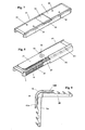
- Figure 1 shows a side view of a male connector 1 prior to installation in a first embodiment.
- the side wall 16 and the bottom 26 are continuous and have centrally a narrow stop web 5, to which the hollow profile strips are pushed from both sides.
- each side ribs 7 are formed profiled.
- the corresponding edge regions of the side walls 16 are each provided with a groove 25.
- the side walls 16 are lowered in each case on both Einsteck Schemeen and occupied with narrow anti-slip webs 12.
- each of softer plastic material web buffer 12 A are introduced, each of which is directed to the connector ends fall off.
- the anti-slip webs 12 protrude beyond the outer profile of the groove 25 and the connector outer side - in the picture above - slightly, so that inserted pushed a press fit to the clear profile of the hollow profile strip.
- a recess 2 In the central connector longitudinal area is a recess 2, which is filled with an excess of butyl putty 9.
- each flaps 3A, 3B are articulated with a film hinge 4.
- Figure 2 shows an end view of the male connector 1, which makes the fairly thick side walls 16, 17 and the continuous bottom 26 clearly.
- FIG. 3 shows a perspective view of the connector 1 according to FIGS. 1 and 2 from the side facing the edge of the pane.
- bridges 27 extend parallel to the bottom 26.
- cover plate 28 containing the shallow recess 2 facing outside, at both ends of which the flaps 3A , 3B hinged to each other and in which the Butylkitt 9 is included in abundance, so that the flap 3A, 3B are slightly pressed upwards inclined before they are inserted into the hollow profile.
- the flaps are each formed in transverse slots 14, 15, so that at a fixed pressing the flaps 3A, 3B to a parallel position to the cover plate 28 of butyl putty 9 from these and from the remaining between the free flap ends gap and to the Side edges emerges and connects to a respective deferred inner wall of the hollow profile strip and glued.
- the spacer strips can be caulked into the slots, providing additional sealing and security against separation. Recesses 80 from caulking are shown on the hollow profile in FIG.
- the lower level of the anti-slip nubble 13 is slightly below the upper edge of the edges of the side walls 16, 17, and the upper plateau of the nubs protrudes by a few tenths of a millimeter in the clear profile of the hollow profile strips 8 B, so that they each show a slight buckling 29 show, thus a very strong hold against retraction arises.
- Figures 4 and 5 show an alternative embodiment of the connector 1 is enlarged, wherein in the perspective view a hollow profile section 8B is partially pushed.
- skid-resistant nubs 13 are molded of soft plastic in this embodiment in addition to the grooves. These nubs 13 are wedge or formed truncated pyramid. They fall to the connector ends each flatter than on the opposite side.
- Figures 6 to 8 show a third embodiment of the male connector 1, wherein the Butylkitt is not yet introduced into the recess 2 and the flaps 3A, 3B still project obliquely.
- Significant difference from the above-described embodiments is the exact fit, in particular of the bottom 26 and the flutes 25 in the clear profile of the hollow profile strips and the dimensional stability of the side walls 16, 17 each containing a steel insert 18, 19, such as the double-enlarged cross-section AA, such as Figure 6 shows.
- the sheet thickness corresponds in the example about a quarter of the side wall thickness. In the bottom region, the metal strip 16, 17 is angled parallel to the bottom 26. The short leg length corresponds approximately to the strip thickness.
- the sheet metal insert also makes it possible to produce very thin, stable side walls which, with small connector cross-sections, leave sufficient space for flow of absorber powder.
- Figure 8 shows the plug-in connector 1 with a plugged up to the stop 5 hollow profile strip 8B and not yet fully pushed bar 8A.
- the flap 3A is already folded down, so that the Butylkitt 9 has leaked into the gap in the joint area and seals it.
- Figure 10 shows a side view of the corner connector 1A as it comes from the injection mold.
- the usually massive corner body 30 which is formed substantially as a cylinder quadrant, extend at right angles to each other two Einsteckarme 31, 32 from the radial surfaces.
- Radially outwardly offset are shorter and thinner flaps 3A, 3B hinged with film hinges at the edges of the quadrant, so that they can be pivoted in each case in the direction of the recess in the outer wall 28 of the adjacent Einsteckarme 31, 32.
- flaps 3A, 3B hinged with film hinges at the edges of the quadrant, so that they can be pivoted in each case in the direction of the recess in the outer wall 28 of the adjacent Einsteckarme 31, 32.
- the Einsteckarme 31, 32 protrude in their longitudinal extent beyond the flaps 3A, 3B and are provided in the protruding areas with retaining louvers 35, 36, which provide a tight fit in the spacer profile.
- the lamellae 35, 36 project beyond the outer walls 28.
- Figure 11 shows a plan view of Figure 10. It can be seen that the Einsteckarme 31, and the flaps 3A, 3B carry at their ends guide slopes.
- the profiles of the corner body 30, the Einsteckarme 31 and the retaining louvers 35 are throaty formed so that they fit to a conventional spacer profile inside or outside.
- the corner body 30 protrudes on all sides with a step 37 beyond the Einsteckarme 31, so that there is a tight stop for the spacer profile is formed. In the local gap sealing the excess of Butylkitt is squeezed, which is introduced under the flap 3A, 3B respectively.
- FIG. 12 shows a variant of a corner connector.
- the flaps 3A, 3B each insertion side of the recess 2 of the Einsteckarme 31, 32 hinged, and the free flap ends reach close to the level 37, 38 which limits the corner body 30.
- the flaps 3A, 3B lie down when pushing the hollow sections over the recess 2 and squeeze Butylkitt in the shock at the stage.
- the one hollow profile end 8 B is shown partially pushed onto the Einsteckarm 32.
Landscapes
- Engineering & Computer Science (AREA)
- Civil Engineering (AREA)
- Structural Engineering (AREA)
- Building Environments (AREA)
- Buffer Packaging (AREA)
- Insulating Bodies (AREA)
Applications Claiming Priority (4)
| Application Number | Priority Date | Filing Date | Title |
|---|---|---|---|
| DE200410054019 DE102004054019B4 (de) | 2004-03-04 | 2004-11-05 | Eckverbinder von Abstandshalteprofilleisten zwischen Isolierglasscheiben |
| DE200420017398 DE202004017398U1 (de) | 2004-11-09 | 2004-11-09 | Eckverbinder für Abstandshalteprofil von Isolierglasscheiben |
| DE200410054602 DE102004054602B3 (de) | 2004-11-11 | 2004-11-11 | Verbinder für Abstandshalterprofilleisten zwischen Isolierglasscheiben |
| DE200510007230 DE102005007230A1 (de) | 2004-11-11 | 2005-02-17 | Verbinder für Abstandshalterprofilleisten zwischen Isolierglasscheiben |
Publications (3)
| Publication Number | Publication Date |
|---|---|
| EP1655448A2 true EP1655448A2 (fr) | 2006-05-10 |
| EP1655448A3 EP1655448A3 (fr) | 2006-12-27 |
| EP1655448B1 EP1655448B1 (fr) | 2009-06-10 |
Family
ID=34982467
Family Applications (1)
| Application Number | Title | Priority Date | Filing Date |
|---|---|---|---|
| EP05004645A Expired - Lifetime EP1655448B1 (fr) | 2004-11-05 | 2005-03-03 | Connecteur pour éléments espacant vitres |
Country Status (3)
| Country | Link |
|---|---|
| EP (1) | EP1655448B1 (fr) |
| AT (1) | ATE433532T1 (fr) |
| DE (1) | DE502005007450D1 (fr) |
Cited By (1)
| Publication number | Priority date | Publication date | Assignee | Title |
|---|---|---|---|---|
| US9432362B2 (en) | 2006-05-09 | 2016-08-30 | Interdigital Technology Corporation | Secure time functionality for a wireless device |
Family Cites Families (2)
| Publication number | Priority date | Publication date | Assignee | Title |
|---|---|---|---|---|
| GB9501349D0 (en) * | 1995-01-24 | 1995-03-15 | Equator Wheels & Sections Ltd | Spacer bars and connectors |
| DE29914919U1 (de) * | 1998-09-10 | 1999-11-25 | Kronenberg, Max, 42657 Solingen | Steckverbinder mit Dichtmittel |
-
2005
- 2005-03-03 EP EP05004645A patent/EP1655448B1/fr not_active Expired - Lifetime
- 2005-03-03 DE DE502005007450T patent/DE502005007450D1/de not_active Expired - Lifetime
- 2005-03-03 AT AT05004645T patent/ATE433532T1/de active
Cited By (2)
| Publication number | Priority date | Publication date | Assignee | Title |
|---|---|---|---|---|
| US9432362B2 (en) | 2006-05-09 | 2016-08-30 | Interdigital Technology Corporation | Secure time functionality for a wireless device |
| US9774457B2 (en) | 2006-05-09 | 2017-09-26 | Interdigital Technology Corporation | Secure time functionality for a wireless device |
Also Published As
| Publication number | Publication date |
|---|---|
| DE502005007450D1 (de) | 2009-07-23 |
| EP1655448A3 (fr) | 2006-12-27 |
| EP1655448B1 (fr) | 2009-06-10 |
| ATE433532T1 (de) | 2009-06-15 |
Similar Documents
| Publication | Publication Date | Title |
|---|---|---|
| DE69310392T2 (de) | Isolierverglasung | |
| DE10023541C2 (de) | Isolierglasscheibe mit Einzelscheiben und mit einem Abstandhalterprofil | |
| DE3327366C2 (fr) | ||
| EP1554455B1 (fr) | Element pour espacer des vitres de vitrages isolants multiples | |
| EP0569986B1 (fr) | Pièce d'assemblage pour profilés creux se raccordant sous un angle | |
| DE2523244A1 (de) | Bausatz fuer gebaeude | |
| WO1999015753A1 (fr) | Profile d'ecartement pour ensemble vitrage isolant | |
| EP0610674A1 (fr) | Joint d'angle à onglet de profilés creux pour cadres de fenêtres, portes ou façades | |
| DE2556167A1 (de) | Flanschverbindung zum gegenseitigen befestigen von im querschnitt im wesentlichen rechteckigen kanalteilstuecken aus blech, insbesondere fuer lufttechnische hochdruckanlagen | |
| DE2625993A1 (de) | Abstandhalterrahmen fuer mehrfach- isolierglasscheiben | |
| DE102005007230A1 (de) | Verbinder für Abstandshalterprofilleisten zwischen Isolierglasscheiben | |
| EP1659254B1 (fr) | Vantail de porte ou fenêtre | |
| DE202012103904U1 (de) | Steckverbinder | |
| DE2619707C3 (de) | Verbundprofil, bestehend aus zwei parallelen Metallteilen und einem Isolationsprofil | |
| EP0033490A1 (fr) | Ensemble de construction pour la fabrication de cadres fixes pour des corps | |
| DE3300599A1 (de) | Verbundprofil | |
| EP1655448A2 (fr) | Connecteur pour éléments espacant vitres | |
| DE3202346A1 (de) | Strangfoermige klemmdichtung | |
| DE202011050843U1 (de) | Steckverbinder | |
| DE3343538A1 (de) | Lamellenfenster | |
| DE202005020587U1 (de) | Verbinder für Abstandshalterprofilleisten zwischen Isolierglasscheiben | |
| EP1531229A1 (fr) | Connecteur enfilable pour profils creux | |
| DE4421867C1 (de) | Verglasungsdichtung | |
| DE69004381T2 (de) | Profildichtung aus Elastomer für Tunnelgewölbe. | |
| EP0100558B1 (fr) | Protection des bords pour vitrage isolant |
Legal Events
| Date | Code | Title | Description |
|---|---|---|---|
| PUAI | Public reference made under article 153(3) epc to a published international application that has entered the european phase |
Free format text: ORIGINAL CODE: 0009012 |
|
| AK | Designated contracting states |
Kind code of ref document: A2 Designated state(s): AT BE BG CH CY CZ DE DK EE ES FI FR GB GR HU IE IS IT LI LT LU MC NL PL PT RO SE SI SK TR |
|
| AX | Request for extension of the european patent |
Extension state: AL BA HR LV MK YU |
|
| PUAL | Search report despatched |
Free format text: ORIGINAL CODE: 0009013 |
|
| AK | Designated contracting states |
Kind code of ref document: A3 Designated state(s): AT BE BG CH CY CZ DE DK EE ES FI FR GB GR HU IE IS IT LI LT LU MC NL PL PT RO SE SI SK TR |
|
| AX | Request for extension of the european patent |
Extension state: AL BA HR LV MK YU |
|
| RIC1 | Information provided on ipc code assigned before grant |
Ipc: E06B 3/667 20060101AFI20061123BHEP |
|
| 17P | Request for examination filed |
Effective date: 20070105 |
|
| 17Q | First examination report despatched |
Effective date: 20070216 |
|
| AKX | Designation fees paid |
Designated state(s): AT BE BG CH CY CZ DE DK EE ES FI FR GB GR HU IE IS IT LI LT LU MC NL PL PT RO SE SI SK TR |
|
| GRAP | Despatch of communication of intention to grant a patent |
Free format text: ORIGINAL CODE: EPIDOSNIGR1 |
|
| GRAS | Grant fee paid |
Free format text: ORIGINAL CODE: EPIDOSNIGR3 |
|
| GRAA | (expected) grant |
Free format text: ORIGINAL CODE: 0009210 |
|
| AK | Designated contracting states |
Kind code of ref document: B1 Designated state(s): AT BE BG CH CY CZ DE DK EE ES FI FR GB GR HU IE IS IT LI LT LU MC NL PL PT RO SE SI SK TR |
|
| REG | Reference to a national code |
Ref country code: GB Ref legal event code: FG4D Free format text: NOT ENGLISH |
|
| REG | Reference to a national code |
Ref country code: CH Ref legal event code: EP |
|
| REG | Reference to a national code |
Ref country code: IE Ref legal event code: FG4D Free format text: LANGUAGE OF EP DOCUMENT: GERMAN |
|
| REF | Corresponds to: |
Ref document number: 502005007450 Country of ref document: DE Date of ref document: 20090723 Kind code of ref document: P |
|
| PG25 | Lapsed in a contracting state [announced via postgrant information from national office to epo] |
Ref country code: LT Free format text: LAPSE BECAUSE OF FAILURE TO SUBMIT A TRANSLATION OF THE DESCRIPTION OR TO PAY THE FEE WITHIN THE PRESCRIBED TIME-LIMIT Effective date: 20090610 Ref country code: FI Free format text: LAPSE BECAUSE OF FAILURE TO SUBMIT A TRANSLATION OF THE DESCRIPTION OR TO PAY THE FEE WITHIN THE PRESCRIBED TIME-LIMIT Effective date: 20090610 |
|
| NLV1 | Nl: lapsed or annulled due to failure to fulfill the requirements of art. 29p and 29m of the patents act | ||
| PG25 | Lapsed in a contracting state [announced via postgrant information from national office to epo] |
Ref country code: NL Free format text: LAPSE BECAUSE OF FAILURE TO SUBMIT A TRANSLATION OF THE DESCRIPTION OR TO PAY THE FEE WITHIN THE PRESCRIBED TIME-LIMIT Effective date: 20090610 Ref country code: SE Free format text: LAPSE BECAUSE OF FAILURE TO SUBMIT A TRANSLATION OF THE DESCRIPTION OR TO PAY THE FEE WITHIN THE PRESCRIBED TIME-LIMIT Effective date: 20090910 Ref country code: SI Free format text: LAPSE BECAUSE OF FAILURE TO SUBMIT A TRANSLATION OF THE DESCRIPTION OR TO PAY THE FEE WITHIN THE PRESCRIBED TIME-LIMIT Effective date: 20090610 Ref country code: PL Free format text: LAPSE BECAUSE OF FAILURE TO SUBMIT A TRANSLATION OF THE DESCRIPTION OR TO PAY THE FEE WITHIN THE PRESCRIBED TIME-LIMIT Effective date: 20090610 |
|
| REG | Reference to a national code |
Ref country code: IE Ref legal event code: FD4D |
|
| PG25 | Lapsed in a contracting state [announced via postgrant information from national office to epo] |
Ref country code: ES Free format text: LAPSE BECAUSE OF FAILURE TO SUBMIT A TRANSLATION OF THE DESCRIPTION OR TO PAY THE FEE WITHIN THE PRESCRIBED TIME-LIMIT Effective date: 20090921 Ref country code: IS Free format text: LAPSE BECAUSE OF FAILURE TO SUBMIT A TRANSLATION OF THE DESCRIPTION OR TO PAY THE FEE WITHIN THE PRESCRIBED TIME-LIMIT Effective date: 20091010 Ref country code: IE Free format text: LAPSE BECAUSE OF FAILURE TO SUBMIT A TRANSLATION OF THE DESCRIPTION OR TO PAY THE FEE WITHIN THE PRESCRIBED TIME-LIMIT Effective date: 20090610 Ref country code: CZ Free format text: LAPSE BECAUSE OF FAILURE TO SUBMIT A TRANSLATION OF THE DESCRIPTION OR TO PAY THE FEE WITHIN THE PRESCRIBED TIME-LIMIT Effective date: 20090610 Ref country code: RO Free format text: LAPSE BECAUSE OF FAILURE TO SUBMIT A TRANSLATION OF THE DESCRIPTION OR TO PAY THE FEE WITHIN THE PRESCRIBED TIME-LIMIT Effective date: 20090610 Ref country code: EE Free format text: LAPSE BECAUSE OF FAILURE TO SUBMIT A TRANSLATION OF THE DESCRIPTION OR TO PAY THE FEE WITHIN THE PRESCRIBED TIME-LIMIT Effective date: 20090610 |
|
| PG25 | Lapsed in a contracting state [announced via postgrant information from national office to epo] |
Ref country code: SK Free format text: LAPSE BECAUSE OF FAILURE TO SUBMIT A TRANSLATION OF THE DESCRIPTION OR TO PAY THE FEE WITHIN THE PRESCRIBED TIME-LIMIT Effective date: 20090610 |
|
| PG25 | Lapsed in a contracting state [announced via postgrant information from national office to epo] |
Ref country code: BG Free format text: LAPSE BECAUSE OF FAILURE TO SUBMIT A TRANSLATION OF THE DESCRIPTION OR TO PAY THE FEE WITHIN THE PRESCRIBED TIME-LIMIT Effective date: 20090910 Ref country code: PT Free format text: LAPSE BECAUSE OF FAILURE TO SUBMIT A TRANSLATION OF THE DESCRIPTION OR TO PAY THE FEE WITHIN THE PRESCRIBED TIME-LIMIT Effective date: 20091010 |
|
| PLBE | No opposition filed within time limit |
Free format text: ORIGINAL CODE: 0009261 |
|
| STAA | Information on the status of an ep patent application or granted ep patent |
Free format text: STATUS: NO OPPOSITION FILED WITHIN TIME LIMIT |
|
| PG25 | Lapsed in a contracting state [announced via postgrant information from national office to epo] |
Ref country code: DK Free format text: LAPSE BECAUSE OF FAILURE TO SUBMIT A TRANSLATION OF THE DESCRIPTION OR TO PAY THE FEE WITHIN THE PRESCRIBED TIME-LIMIT Effective date: 20090610 |
|
| 26N | No opposition filed |
Effective date: 20100311 |
|
| PG25 | Lapsed in a contracting state [announced via postgrant information from national office to epo] |
Ref country code: MC Free format text: LAPSE BECAUSE OF NON-PAYMENT OF DUE FEES Effective date: 20100331 Ref country code: GR Free format text: LAPSE BECAUSE OF FAILURE TO SUBMIT A TRANSLATION OF THE DESCRIPTION OR TO PAY THE FEE WITHIN THE PRESCRIBED TIME-LIMIT Effective date: 20090911 |
|
| REG | Reference to a national code |
Ref country code: FR Ref legal event code: ST Effective date: 20101130 |
|
| PG25 | Lapsed in a contracting state [announced via postgrant information from national office to epo] |
Ref country code: FR Free format text: LAPSE BECAUSE OF NON-PAYMENT OF DUE FEES Effective date: 20100331 |
|
| PG25 | Lapsed in a contracting state [announced via postgrant information from national office to epo] |
Ref country code: IT Free format text: LAPSE BECAUSE OF FAILURE TO SUBMIT A TRANSLATION OF THE DESCRIPTION OR TO PAY THE FEE WITHIN THE PRESCRIBED TIME-LIMIT Effective date: 20090610 |
|
| PG25 | Lapsed in a contracting state [announced via postgrant information from national office to epo] |
Ref country code: CY Free format text: LAPSE BECAUSE OF FAILURE TO SUBMIT A TRANSLATION OF THE DESCRIPTION OR TO PAY THE FEE WITHIN THE PRESCRIBED TIME-LIMIT Effective date: 20090610 |
|
| PG25 | Lapsed in a contracting state [announced via postgrant information from national office to epo] |
Ref country code: LU Free format text: LAPSE BECAUSE OF NON-PAYMENT OF DUE FEES Effective date: 20100303 Ref country code: HU Free format text: LAPSE BECAUSE OF FAILURE TO SUBMIT A TRANSLATION OF THE DESCRIPTION OR TO PAY THE FEE WITHIN THE PRESCRIBED TIME-LIMIT Effective date: 20091211 |
|
| PG25 | Lapsed in a contracting state [announced via postgrant information from national office to epo] |
Ref country code: TR Free format text: LAPSE BECAUSE OF FAILURE TO SUBMIT A TRANSLATION OF THE DESCRIPTION OR TO PAY THE FEE WITHIN THE PRESCRIBED TIME-LIMIT Effective date: 20090610 |
|
| PGFP | Annual fee paid to national office [announced via postgrant information from national office to epo] |
Ref country code: GB Payment date: 20130320 Year of fee payment: 9 Ref country code: CH Payment date: 20130322 Year of fee payment: 9 |
|
| PGFP | Annual fee paid to national office [announced via postgrant information from national office to epo] |
Ref country code: BE Payment date: 20130328 Year of fee payment: 9 |
|
| REG | Reference to a national code |
Ref country code: CH Ref legal event code: PL |
|
| GBPC | Gb: european patent ceased through non-payment of renewal fee |
Effective date: 20140303 |
|
| PG25 | Lapsed in a contracting state [announced via postgrant information from national office to epo] |
Ref country code: LI Free format text: LAPSE BECAUSE OF NON-PAYMENT OF DUE FEES Effective date: 20140331 Ref country code: CH Free format text: LAPSE BECAUSE OF NON-PAYMENT OF DUE FEES Effective date: 20140331 Ref country code: GB Free format text: LAPSE BECAUSE OF NON-PAYMENT OF DUE FEES Effective date: 20140303 |
|
| REG | Reference to a national code |
Ref country code: DE Ref legal event code: R082 Ref document number: 502005007450 Country of ref document: DE Representative=s name: FIEDLER, OSTERMANN & SCHNEIDER, DE |
|
| PGFP | Annual fee paid to national office [announced via postgrant information from national office to epo] |
Ref country code: AT Payment date: 20160318 Year of fee payment: 12 |
|
| PG25 | Lapsed in a contracting state [announced via postgrant information from national office to epo] |
Ref country code: BE Free format text: LAPSE BECAUSE OF NON-PAYMENT OF DUE FEES Effective date: 20140331 |
|
| REG | Reference to a national code |
Ref country code: AT Ref legal event code: MM01 Ref document number: 433532 Country of ref document: AT Kind code of ref document: T Effective date: 20170303 |
|
| PG25 | Lapsed in a contracting state [announced via postgrant information from national office to epo] |
Ref country code: AT Free format text: LAPSE BECAUSE OF NON-PAYMENT OF DUE FEES Effective date: 20170303 |
|
| PGFP | Annual fee paid to national office [announced via postgrant information from national office to epo] |
Ref country code: DE Payment date: 20220225 Year of fee payment: 18 |
|
| REG | Reference to a national code |
Ref country code: DE Ref legal event code: R119 Ref document number: 502005007450 Country of ref document: DE |
|
| PG25 | Lapsed in a contracting state [announced via postgrant information from national office to epo] |
Ref country code: DE Free format text: LAPSE BECAUSE OF NON-PAYMENT OF DUE FEES Effective date: 20231003 |