EP1655456A2 - Installation de production d'énergie à turbine à gaz - Google Patents
Installation de production d'énergie à turbine à gaz Download PDFInfo
- Publication number
- EP1655456A2 EP1655456A2 EP05024100A EP05024100A EP1655456A2 EP 1655456 A2 EP1655456 A2 EP 1655456A2 EP 05024100 A EP05024100 A EP 05024100A EP 05024100 A EP05024100 A EP 05024100A EP 1655456 A2 EP1655456 A2 EP 1655456A2
- Authority
- EP
- European Patent Office
- Prior art keywords
- liquid fuel
- fuel
- gas
- gaseous fuel
- mixing chamber
- Prior art date
- Legal status (The legal status is an assumption and is not a legal conclusion. Google has not performed a legal analysis and makes no representation as to the accuracy of the status listed.)
- Granted
Links
Images




Classifications
-
- F—MECHANICAL ENGINEERING; LIGHTING; HEATING; WEAPONS; BLASTING
- F23—COMBUSTION APPARATUS; COMBUSTION PROCESSES
- F23R—GENERATING COMBUSTION PRODUCTS OF HIGH PRESSURE OR HIGH VELOCITY, e.g. GAS-TURBINE COMBUSTION CHAMBERS
- F23R3/00—Continuous combustion chambers using liquid or gaseous fuel
- F23R3/28—Continuous combustion chambers using liquid or gaseous fuel characterised by the fuel supply
- F23R3/36—Supply of different fuels
-
- F—MECHANICAL ENGINEERING; LIGHTING; HEATING; WEAPONS; BLASTING
- F01—MACHINES OR ENGINES IN GENERAL; ENGINE PLANTS IN GENERAL; STEAM ENGINES
- F01D—NON-POSITIVE DISPLACEMENT MACHINES OR ENGINES, e.g. STEAM TURBINES
- F01D15/00—Adaptations of machines or engines for special use; Combinations of engines with devices driven thereby
- F01D15/10—Adaptations for driving, or combinations with, electric generators
-
- F—MECHANICAL ENGINEERING; LIGHTING; HEATING; WEAPONS; BLASTING
- F02—COMBUSTION ENGINES; HOT-GAS OR COMBUSTION-PRODUCT ENGINE PLANTS
- F02C—GAS-TURBINE PLANTS; AIR INTAKES FOR JET-PROPULSION PLANTS; CONTROLLING FUEL SUPPLY IN AIR-BREATHING JET-PROPULSION PLANTS
- F02C3/00—Gas-turbine plants characterised by the use of combustion products as the working fluid
- F02C3/20—Gas-turbine plants characterised by the use of combustion products as the working fluid using a special fuel, oxidant, or dilution fluid to generate the combustion products
-
- F—MECHANICAL ENGINEERING; LIGHTING; HEATING; WEAPONS; BLASTING
- F02—COMBUSTION ENGINES; HOT-GAS OR COMBUSTION-PRODUCT ENGINE PLANTS
- F02C—GAS-TURBINE PLANTS; AIR INTAKES FOR JET-PROPULSION PLANTS; CONTROLLING FUEL SUPPLY IN AIR-BREATHING JET-PROPULSION PLANTS
- F02C3/00—Gas-turbine plants characterised by the use of combustion products as the working fluid
- F02C3/20—Gas-turbine plants characterised by the use of combustion products as the working fluid using a special fuel, oxidant, or dilution fluid to generate the combustion products
- F02C3/22—Gas-turbine plants characterised by the use of combustion products as the working fluid using a special fuel, oxidant, or dilution fluid to generate the combustion products the fuel or oxidant being gaseous at standard temperature and pressure
-
- F—MECHANICAL ENGINEERING; LIGHTING; HEATING; WEAPONS; BLASTING
- F02—COMBUSTION ENGINES; HOT-GAS OR COMBUSTION-PRODUCT ENGINE PLANTS
- F02C—GAS-TURBINE PLANTS; AIR INTAKES FOR JET-PROPULSION PLANTS; CONTROLLING FUEL SUPPLY IN AIR-BREATHING JET-PROPULSION PLANTS
- F02C3/00—Gas-turbine plants characterised by the use of combustion products as the working fluid
- F02C3/20—Gas-turbine plants characterised by the use of combustion products as the working fluid using a special fuel, oxidant, or dilution fluid to generate the combustion products
- F02C3/24—Gas-turbine plants characterised by the use of combustion products as the working fluid using a special fuel, oxidant, or dilution fluid to generate the combustion products the fuel or oxidant being liquid at standard temperature and pressure
-
- F—MECHANICAL ENGINEERING; LIGHTING; HEATING; WEAPONS; BLASTING
- F23—COMBUSTION APPARATUS; COMBUSTION PROCESSES
- F23R—GENERATING COMBUSTION PRODUCTS OF HIGH PRESSURE OR HIGH VELOCITY, e.g. GAS-TURBINE COMBUSTION CHAMBERS
- F23R3/00—Continuous combustion chambers using liquid or gaseous fuel
- F23R3/28—Continuous combustion chambers using liquid or gaseous fuel characterised by the fuel supply
- F23R3/34—Feeding into different combustion zones
- F23R3/343—Pilot flames, i.e. fuel nozzles or injectors using only a very small proportion of the total fuel to insure continuous combustion
Definitions
- the present invention relates to a gas turbine power generating machine. More particularly, the present invention relates to a gas turbine power generating machine which is installed near gas fields or oil fields and which transmits generated electricity to a consuming area through a power transmission system.
- Natural gas produced in a gas field is transported to a consuming area, for example, by a method of liquefying the natural gas with a liquefaction facility near the gas field and transporting the liquefied natural gas to the consuming area by land or sea, or by a method of transporting the natural gas, as it is, to the consuming area through pipelines.
- the pipelines include several booster stations for boosting the pressure of natural gas to compensate for a pressure loss caused while the natural gas flows through the pipelines. The interval between the booster stations is, e.g., several tens to several hundreds kilometers. Constructions of general gas-turbine power generating machine are disclosed in, e.g., Patent Document 1 (JP,A 2003-166428) and Patent Reference 2 (JP,A 2002-327629).
- the related art requires a great deal of initial investment for the gas liquefaction facility, the pipelines, etc. Also, in medium- or small-scaled gas fields and in gas fields that have become overage with the progress of gas extraction, outturn is relatively small and a profit is no longer expected because of an increase in cost of the fuel transporting system relative to the outturn. For that reason, the natural gas (gaseous fuel) extracted from the medium- or small-scaled gas fields and the overage gas fields has not been transported to the consuming area and hence has not been effectively utilized.
- liquid fuel such as associated oil produced concurrently during the extraction of natural gas and condensates (hydrocarbons being liquid at room temperature and atmospheric pressure) generated in the refining process of natural gas
- it is hard to ensure a profit because of an increase in the fuel transporting cost as in the above-mentioned case. Therefore, that liquid fuel has not also been effectively utilized.
- liquid fuel such as associated oil produced concurrently during the extraction of natural gas and condensates (hydrocarbons being liquid at room temperature and atmospheric pressure) generated in the refining process of natural gas
- it is hard to ensure a profit because of an increase in the fuel transporting cost as in the above-mentioned case. Therefore, that liquid fuel has not also been effectively utilized.
- medium- or small-scaled oil fields and overage oil fields it is similarly hard to ensure a profit because of an increase in the fuel transporting cost as in the above-mentioned gas fields.
- an object of the present invention is to provide a gas turbine power generating machine which can effectively utilize natural gas extracted from medium- or small-scaled gas fields and overage gas fields, liquid fuel produced during the extraction and refining process of the natural gas, as well as liquid fuel and gaseous fuel, such as associated gas, produced in medium- or small-scaled oil fields and overage oil fields.
- the present invention provides a gas turbine power generating machine installed near a gas field and/or an oil field and transmitting generated electricity to a consuming area through a power transmission system, the gas turbine power generating machine comprising a gaseous fuel processing apparatus for pre-processing natural gas produced in the gas field and/or gaseous fuel, including associated gas, produced in the oil field; a liquid fuel processing apparatus for pre-processing liquid fuel obtained during extraction and a refining process of the natural gas and/or liquid fuel produced in the oil field; and a gas turbine comprising a compressor for generating compressed air, a combustor for mixing the compressed air from the compressor with one or both of the gaseous fuel pre-processed by the gaseous fuel processing apparatus and the liquid fuel pre-processed by the liquid fuel processing apparatus, and for burning a gas mixture, and a turbine for driving a generator by combustion gases supplied from the combustor.
- a gaseous fuel processing apparatus for pre-processing natural gas produced in the gas field and/or gaseous fuel,
- the gas turbine power generating machine is installed near, e.g., a medium- or small-scaled gas field or an overage gas field.
- the gaseous fuel and the liquid fuel are pre-processed respectively by the gaseous fuel processing apparatus and the liquid fuel processing apparatus.
- the gas turbine generates electric power by using one or both of the pre-processed gaseous fuel and liquid fuel, and the generated electric power is transmitted to the consuming area through the power transmission system.
- the cost is cut with elimination of not only pipelines for transporting the gaseous fuel, but also liquefaction equipment, transportation equipment, etc. for liquefying and transporting the gaseous fuel, whereby the gaseous fuel and the liquid fuel both having been left unused in the past can be effectively utilized. It is therefore possible to effectively utilize natural gas extracted from medium- or small-scaled gas fields and overage gas fields, and liquid fuel produced during the extraction and refining process of the natural gas.
- the gas turbine power generating machine further comprises an amount-of-produced gaseous fuel sensor for detecting an amount of the gaseous fuel produced and pre-processed by the gaseous fuel processing apparatus; an amount-of-produced liquid fuel sensor for detecting an amount of the liquid fuel produced and pre-processed by the liquid fuel processing apparatus; an exhaust gas temperature sensor for detecting a temperature of exhaust gas of the turbine; a power output sensor for detecting a power output generated by the generator; and a fuel supply control unit for controlling supply of the gaseous fuel and the liquid fuel to the combustor depending on results detected by the sensors.
- an amount-of-produced gaseous fuel sensor for detecting an amount of the gaseous fuel produced and pre-processed by the gaseous fuel processing apparatus
- an amount-of-produced liquid fuel sensor for detecting an amount of the liquid fuel produced and pre-processed by the liquid fuel processing apparatus
- an exhaust gas temperature sensor for detecting a temperature of exhaust gas of the turbine
- a power output sensor for detecting a power output generated
- the fuel supply control unit controls respective amounts of the gaseous fuel and the liquid fuel supplied to the combustor such that the exhaust gas temperature detected by the exhaust gas temperature sensor does not exceed a predetermined upper limit value.
- the fuel supply control unit executes control such that only the gaseous fuel is supplied to the combustor until the power output detected by the power output sensor reaches a predetermined intermediate output, and such that the gaseous fuel and the liquid fuel are both supplied to the combustor after the power output detected by the power output sensor exceeds the predetermined intermediate output.
- the fuel supply control unit executes control such that the gaseous fuel is supplied to the combustor at a maximum limit of the amount of the produced gaseous fuel, which is detected by the amount-of-produced gaseous fuel sensor, and such that the liquid fuel is supplied to the combustor in amount to compensate for a deficiency in amount of the supplied gaseous fuel.
- the combustor comprises a liquid fuel atomizer for atomization of the liquid fuel; a mixing chamber wall having a hollow conical shape gradually spreading in the direction of the atomization of the liquid fuel atomizer and defining a mixing chamber therein with the liquid fuel atomizer disposed at a center of the mixing chamber wall; a plurality of air inlet holes bored in the mixing chamber wall and introducing the compressed air supplied from the compressor such that angles at which the compressed air is introduced to the mixing chamber are deviated at least toward the circumferential direction of the mixing chamber; and a plurality of gaseous fuel nozzles disposed on the outer side of the mixing chamber wall in opposed relation to the air inlet holes and ejecting the gaseous fuel in directions substantially coaxial with respective axes of the air inlet holes.
- the combustor comprises a pilot burner and a plurality of main burners disposed around the pilot burner, each of the pilot burner and the main burners comprising a liquid fuel atomizer for atomization of the liquid fuel; a mixing chamber wall having a hollow conical shape gradually spreading in the direction of the atomization of the liquid fuel atomizer and defining a mixing chamber therein with the liquid fuel atomizer disposed at a center of the mixing chamber wall; a plurality of air inlet holes bored in the mixing chamber wall and introducing the compressed air supplied from the compressor such that angles at which the compressed air is introduced to the mixing chamber are deviated at least toward the circumferential direction of the mixing chamber; and a plurality of gaseous fuel nozzles disposed on the outer side of the mixing chamber wall in opposed relation to the air inlet holes and ejecting the gaseous fuel in directions substantially coaxial with respective axes of the air inlet holes.
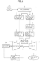
- Fig. 1 is a block diagram showing an overall construction of the gas turbine power generating machine according to the first embodiment. Note that this first embodiment is described, by way of example, in connection with the case using natural gas (gaseous fuel) extracted from gas fields and liquid fuel produced during the extraction and refining process of the natural gas.
- natural gas gaseous fuel
- the gas turbine power generating machine is installed near a gas field 1.
- the gas turbine power generating machine comprises a fuel separator 2 for separating natural gas (gaseous fuel) from liquid gas, such as associated oil produced concurrently during extraction of the natural, a gaseous fuel processing apparatus 3 for pre-processing the natural gas separated by the fuel separator 2 to be ready for combustion, a gaseous fuel supply apparatus 5 for supplying the gaseous fuel pre-processed by the gaseous fuel processing apparatus 3 to a combustor 4 (described in detail later), a liquid fuel processing apparatus 6 for pre-processing liquid fuel, such as condensates generated in the refining process of natural gas and associated oil separated by the fuel separator 2 to be ready for combustion, a liquid fuel reservoir 7 for storing the liquid fuel pre-processed by the liquid fuel processing apparatus 6, a liquid fuel supply apparatus 8 for supplying the liquid fuel from the liquid fuel reservoir 7 to the combustor 4, a gas turbine 9 driven by using the gaseous fuel and the liquid fuel supplied
- the gas turbine 9 comprises a compressor 13 for generating compressed air, the combustor 4 for mixing the gaseous fuel and the liquid fuel supplied respectively from the gaseous fuel supply apparatus 5 and the liquid fuel processing apparatus 8 (or one of the gaseous fuel and the liquid fuel) with the compressed air from the compressor 13 and for burning the mixture, and a turbine 14 driven by combustion gases supplied from the combustor 4.
- the compressor 13 and the generator 10 are coaxially coupled to the turbine 14 so that the compressor 13 and the generator 10 are driven with the operation of the turbine 14 and the generator 10 generates electric power.
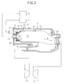
- Fig. 2 is a side sectional view showing a principal structure of the combustor 4
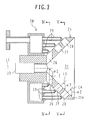
- Fig. 3 is a side sectional view showing a detailed structure of a burner (described later)
- Fig. 4 is a sectional view taken along the line IV-IV in Fig. 3
- Fig. 5 is a sectional view taken along the line V-V in Fig. 3.
- the combustor 4 is disposed in plural at substantially equal angular intervals around the compressor 13.
- a casing of the combustor 4 comprises an outer casing 15 and an liner 16 each having a substantially cylindrical shape, and an end cover 17 disposed at one end (left side as viewed in Fig. 2) of the outer casing 15.
- the liner 16 is disposed inside the outer casing 15 with a gap left between them, and the gap defines a channel 18 for the compressed air supplied from the compressor 13.
- An inner space of the liner 16 defines a combustion chamber 19 for burning the compressed air and the fuel therein.
- a burner 20 is disposed which ejects the fuel for mixing of the fuel with the compressed air (indicated by arrow A in Fig. 2) supplied through the compressed gas channel 18.
- the gas mixture from the burner 20 is introduced to the combustion chamber 19 inside the liner 16.
- the combustion chamber 19 inside the liner 16 is provided with an igniter 21 for igniting the gas mixture.
- the gas mixture is burnt to produce the combustion gases that are supplied to the turbine 14 through a transition piece 22 (as indicated by an arrow B in Fig. 2).
- the burner 20 comprises a liquid fuel atomizer 23 for atomization of the liquid fuel, and a mixing chamber wall 25 having a hollow conical shape gradually spreading toward the combustion chamber 19 (to the right as viewed in Figs. 2 and 3) and defining a mixing chamber 24 therein with the liquid fuel atomizer 23 disposed at a center (apex of the conical shape) of the mixing chamber wall 25.
- the liquid fuel atomizer 23 atomizes the liquid fuel in a direction substantially coaxial with an axis L1 of the mixing chamber wall 25.
- Air inlet holes 26, 27 and 28 for introducing, to the mixing chamber 24, the compressed air supplied through the compressed air channel 18 are bored in the mixing chamber wall 25 in plural stages (three in this embodiment) in the direction of the axis L1 and in plural points (six in this embodiment) in the circumferential direction per stage such that those air inlet holes 26, 27 and 28 are arranged successively in this order from the upstream side (i.e., from the left side as viewed in Fig. 3). Further, a plurality of gaseous fuel nozzles 29 are disposed on the outer side of the mixing chamber wall 25 in opposed relation to the air inlet holes 26, 27 and 28, respectively.
- the gaseous fuel nozzles 29 eject the gaseous fuel in directions substantially coaxial with respective axes L2, L3 and L4 of the air inlet holes 26, 27 and 28. Additionally, the liquid fuel is supplied to the liquid fuel atomizer 23 from the liquid fuel supply apparatus 8, and the gaseous fuel is supplied to the plurality of gaseous fuel nozzles 29 from the gaseous fuel supply apparatus 5.
- the air inlet holes 26, 27 and 28 are bored in the mixing chamber wall 25 such that angles at which the compressed air is introduced through those air inlet holes are deviated at least toward the circumferential direction of the mixing chamber wall 25.
- X represents the offset distance between the axis L2, L4 of the air inlet hole 26, 28 and the axis L1 of the mixing chamber wall 25 (i.e., the length of a segment connecting the axis L2, L4 and the axis L1 in perpendicular relation)
- D represents the inner diameter of the mixing chamber wall 25 at each axial position where the air inlet hole 26, 28 is bored.
- the air inlet holes 26, 27 and 28 in the mixing chamber wall 25 are formed such that X/D increases as an axial position approaches the downstream side (to the right as viewed in Fig. 3).
- X/D takes a smaller value at the air inlet hole 26 in the upstream stage.
- the compressed air flows in toward the vicinity of the axis L1 of the mixing chamber wall 25 (i.e., the vicinity of the position where the liquid fuel is atomized from the liquid fuel atomizer 23).
- X/D takes a larger value at the air inlet hole 28 in the downstream stage. Therefore, the compressed air flows in substantially along an inner circumferential surface 25a of the mixing chamber wall 25, as indicated by an arrow A2 in Fig. 5.
- angles at which the axes L2, L3 and L4 of the air inlet holes 26, 27 and 28 extend are also changed depending on positions in the direction of the axis L1. More specifically, as shown in Fig. 3, the air inlet hole 26 in the upstream stage has a relatively large angle ⁇ 1 between its axis L2 and the inner circumferential surface 25a of the mixing chamber wall 25 (e.g., such an angle as causing a plane including the axis L2 of the air inlet hole 26 to intersect the axis L1 substantially at a right angle).
- the air inlet holes 27, 28 in the intermediate and downstream stages have a relatively small angle ⁇ 2 (e.g., about 90°) between their axes L3, L4 and the inner circumferential surface 25a of the mixing chamber wall 25.
- ⁇ 2 e.g., about 90°
- the compressed air ejected from the air inlet hole 26 in the upstream stage flows into the mixing chamber 24 substantially at a right angle relative to the axis L1 of the mixing chamber wall 25 (i.e., to the liquid fuel atomized from the liquid fuel atomizer 23).
- the gas turbine power generating machine of this embodiment is installed near, e.g., a medium- or small-scaled gas field or an overage gas field.
- the fuel separator 2 separates natural gas (gaseous fuel) from liquid fuel, such as associated oil produced concurrently during extraction of the natural gas.
- the gaseous fuel processing apparatus 3 pre-processes the natural gas separated by the fuel separator 2.
- the liquid fuel processing apparatus 6 pre-processes the liquid fuel, such as condensates generated in the refining process of natural gas and associated oil separated by the fuel separator 2.
- the gas turbine 9 is driven by using the pre-processed gaseous fuel and liquid fuel (or one of them), and the generator 10 generates electric power.
- the generated electric power is transmitted to the consuming area 11 through the power transmission system 12.
- the cost is cut with elimination of not only pipelines for transporting the gaseous fuel, but also liquefaction equipment, transportation equipment, etc. for liquefying and transporting the gaseous fuel, whereby the gaseous fuel and the liquid fuel both having been left unused in the past can be effectively utilized. It is hence possible to effectively utilize natural gas extracted from medium- or small-scaled gas fields and overage gas fields, and liquid fuel produced during the extraction and refining process of the natural gas.
- liquid fuel often contains heavy metals causing high temperature gas corrosion, e.g., vanadium, and the content of heavy metals with respect to the amount of fuel supplied to the combustor 4 (i.e., the total amount of heat generated) is specified for the purpose of suppressing the high temperature gas corrosion. Accordingly, if the content of heavy metals exceeds the specified value, the heavy metals have to be removed from the liquid fuel, thus resulting in an increase of the cost.
- the combustor 4 in this embodiment is capable of burning both of the gaseous fuel and the liquid fuel, the combustion ratio of the liquid fuel can be reduced so that the content of heavy metals with respect to the total amount of heat generated is kept below the specified value. As a result, the necessity of removing the heavy metals in the liquid fuel is eliminated and the cost is cut correspondingly. In addition, the equipment cost can also be cut because of no need of preparing separate combustors for the gaseous fuel and the liquid fuel.
- the mixing chamber wall 25 having a hollow conical shape and a small reflectance is disposed in the inlet portion of the combustor 4 serving as the other reflecting end, the pressure wave is damped by the mixing chamber wall 25 when it impinges upon the mixing chamber wall 25, whereby the generation of the combustion driven oscillation can be suppressed.
- a second embodiment of the present invention will be described below with reference to Figs. 6-9.
- This second embodiment is intended to control respective amounts of the gaseous fuel and the liquid fuel supplied to the combustor 4.
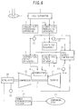
- Fig. 6 is a block diagram showing an overall construction of a gas turbine power generating machine according to the second embodiment. Components in Fig. 6 identical to those in the first embodiment are denoted by the same symbols and a duplicate description of those components is omitted here.
- the gas turbine power generating machine additionally comprises an amount-of-produced gaseous fuel sensor 31 for detecting the amount of the gaseous fuel produced and pre-processed by the gaseous fuel processing apparatus 3, an amount-of-produced liquid fuel sensor 32 for detecting the amount of the liquid fuel produced and pre-processed by the liquid fuel processing apparatus 6, an exhaust gas temperature sensor 33 for detecting the temperature of exhaust gas of the turbine 14, a power output sensor 34 for detecting the power output generated by the generator 10, and a fuel supply controller (fuel supply control means) 35 for controlling the amounts of the gaseous fuel and the liquid fuel supplied to the combustor 4 depending on the results detected by the sensors 31-34.
- an amount-of-produced gaseous fuel sensor 31 for detecting the amount of the gaseous fuel produced and pre-processed by the gaseous fuel processing apparatus 3
- an amount-of-produced liquid fuel sensor 32 for detecting the amount of the liquid fuel produced and pre-processed by the liquid fuel processing apparatus 6
- an exhaust gas temperature sensor 33 for detecting the temperature of exhaust
- the fuel supply controller 35 receives detected signals from the sensors 31-34 and executes predetermined arithmetic and logical operations to generate control signals.
- the control signals are outputted to the gaseous fuel supply apparatus 5 and the liquid fuel supply apparatus 8, thereby controlling the amount of the gaseous fuel supplied to the combustor 4 by the gaseous fuel supply apparatus 5 and the amount of the liquid fuel supplied to the combustor 4 by the fluid fuel supply apparatus 8.
- the fuel supply controller 35 controls the amounts of the supplied gaseous fuel and liquid fuel with respect to the flow rate of the compressed air so that the exhaust gas temperature detected by the exhaust gas temperature sensor 33 does not exceed a predetermined upper limit temperature, which has been set and stored in advance.
- the fuel supply controller 35 controls the amounts of the supplied gaseous fuel and liquid fuel so as to adjust the power output of the generator 10 within the range where the exhaust gas temperature does not exceed the predetermined upper limit temperature.
- the fuel supply controller 35 can control the amounts of the supplied gaseous fuel and liquid fuel by changing both of those amounts, it is preferable to execute the control by changing one of the amounts of the supplied gaseous fuel and liquid fuel from the viewpoint of avoiding a complicated control process.
- the fuel supply control executed by the fuel supply controller 35 will be described in detail below.
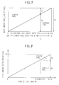
- Fig. 7 is a characteristic graph showing the relationship between a gaseous-fuel/liquid-fuel supply ratio and heat amounts supplied by the gaseous fuel and the liquid fuel in rated-load operation of the gas turbine 9.
- the horizontal axis represents the gaseous-fuel/liquid-fuel supply ratio, i.e., respective supply rates of the gaseous fuel and the liquid fuel
- the vertical axis represents the heat amount supplied by the gaseous fuel (on the side below a slope line in Fig. 7) and the heat amount supplied by the liquid fuel (on the side above the slope line in Fig. 7).
- the supply rate of the gaseous fuel is increased from 0% to 100% toward the right along the horizontal axis, and the heat amount supply by the gaseous fuel is monotonously increased as the supply rate of the gaseous fuel increases.
- the supply rate of the liquid fuel is increased from 0% to 100% toward the left along the horizontal axis, and the heat amount supplied by the liquid fuel is monotonously increased as the supply rate of the liquid fuel increases. Then, at each point on the horizontal axis, the sum of the supply rates of the gaseous fuel and the liquid fuel is 100%, and a total supplied heat amount given as the sum of the heat amounts supplied by the gaseous fuel and the liquid fuel is set to a predetermined value Q T required for the rated-load operation of the gas turbine 9.
- the fuel supply controller 35 is capable of not only changing the gaseous-fuel/liquid-fuel supply ratio from the supply rate 100% of the gaseous fuel to the supply rate 100% of the liquid fuel, but also setting the gaseous-fuel/liquid-fuel supply ratio to any desired value within the range where the exhaust gas temperature does not exceed the predetermined upper limit temperature. For example, when the gaseous-fuel/liquid-fuel supply ratio is set to a value indicated by a point C on the horizontal axis in Fig. 7, the heat amounts supplied by the gaseous fuel and the liquid fuel are Q V , Q L , respectively.
- One example of the fuel supply control executed by the fuel supply controller 35 from the startup of the gas turbine 9 to the rated-load operation will be described below with reference to Fig. 8.
- the horizontal axis represents the load of the gas turbine 9
- the vertical axis represents the respective heat amounts supplied by the gaseous fuel and the liquid fuel.
- the total heat amount supplied by the gaseous fuel and the liquid fuel is monotonously increased depending on the load of the gas turbine 9.
- the fuel supply controller 35 executes the fuel supply control as follows. Until the load (e.g., the load converted from the power output detected by the power output sensor 34) of the gas turbine 9 reaches a predetermined intermediate load, only the gaseous fuel is supplied and the heat amount supplied by the gaseous fuel is monotonously increased depending on the load.
- the heat amount supplied by the liquid fuel is monotonously increased while the heat amount supplied by the gaseous fuel is monotonously reduced depending on the load. Then, when the gas turbine 9 is brought into the rated-load operation, the heat amounts supplied by the gaseous fuel and the liquid fuel are given as, e.g., Q V and Q L , respectively (see Fig. 7).
- Fig. 9 is a characteristic graph showing changes with time of the heat amounts supplied by the gaseous fuel and the liquid fuel in the rated-load operation of the gas turbine 9.
- the horizontal axis represents time
- the vertical axis represents the respective heat amounts supplied by the gaseous fuel and the liquid fuel.
- the fuel supply controller 35 executes the fuel supply control such that the gaseous fuel is supplied to the combustor 4 at a maximum limit of the amount of the produced gaseous fuel, which is detected by the amount-of-produced gaseous fuel sensor 31. Under such control, the heat amount supplied by the gaseous fuel is changed with time in some cases.
- the gas turbine power generating machine can be adapted for the case where the amounts of the gaseous fuel and the liquid fuel produced in the medium- or small-scaled gas fields and the overage gas fields are changed, and can stably supply electric power to the consuming area 11.
- the second embodiment is also able to effectively utilize natural gas extracted from medium- or small-scaled gas fields and overage gas fields, and liquid fuel produced during the extraction and refining process of the natural gas.
- the present invention is not limited to such a process.
- a liquid-fuel storage amount sensor for detecting the amount of the liquid fuel stored in the liquid fuel reservoir 7 may be disposed, and a detected signal from that sensor may be inputted to the fuel supply controller 35 to execute the predetermined arithmetic and logical operations.
- This modification can also provide similar advantages to those described above.
- Fig. 10 is a side sectional view showing a principal structure of a combustor according to the modification
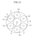
- Fig. 11 is a sectional view taken along the line XI-XI in Fig. 10.
- Components in Figs. 10 and 11 identical to those in the above embodiments are denoted by the same symbols and a duplicate description of those components is omitted here.
- a combustor 36 comprises a pilot burner 37 and a plurality of main burners 38A-38F disposed around the pilot burner 37. Gas mixtures ejected from these burners 37 and 38A-38F are introduced to a combustion chamber 19 defined in an liner 16. A plate 39 is disposed between an outlet of the pilot burner 37 and outlets of the main burners 38A-38F to assist stable combustion.
- the burners 37 and 38A-38F are each of a similar structure to that of the burner 20 in the above-described embodiments though differing in size.
- Liquid fuel is supplied from a first liquid fuel supply apparatus 40 to a liquid fuel atomizer 23 of the pilot burner 37, and gaseous fuel is supplied from a first gaseous fuel supply apparatus 41 to a gaseous fuel injector 29 of the pilot burner 37. Also, liquid fuel is supplied from a second liquid fuel supply apparatus 42 to liquid fuel atomizers 23 of the main burners 38A-38F, and gaseous fuel is supplied from a second gaseous fuel supply apparatus 43 to gaseous fuel injectors 29 of the main burners 38A-38F.
- Supply ratios between the gaseous fuel and the liquid fuel supplied to the pilot burner 37 and the main burners 38A-38F may be set to different values or the same value. Also, a fuel supply method may be modified, for example, such that only the liquid fuel is supplied to any of the pilot burner 37 and the main burners 38A-38F, and only the gaseous fuel is supplied to the others.
- the gas turbine power generating machine may be installed near an oil field and may employ liquid fuel extracted from the oil field (e.g., petroleum and residual oil obtained in the refining process thereof), and gaseous fuel, such as associated gas, produced concurrently with the extraction of oil.
- liquid fuel extracted from the oil field e.g., petroleum and residual oil obtained in the refining process thereof
- gaseous fuel such as associated gas
- the gas turbine and other associated equipment may be assembled in a packaged structure so that a power generating machine can be easily conveyed by transporting means, such as a trailer.
- transporting means such as a trailer.
- the equipment cost can be cut in that case.
Landscapes
- Engineering & Computer Science (AREA)
- Mechanical Engineering (AREA)
- General Engineering & Computer Science (AREA)
- Chemical & Material Sciences (AREA)
- Combustion & Propulsion (AREA)
- Engine Equipment That Uses Special Cycles (AREA)
Applications Claiming Priority (1)
| Application Number | Priority Date | Filing Date | Title |
|---|---|---|---|
| JP2004320976A JP4509742B2 (ja) | 2004-11-04 | 2004-11-04 | ガスタービン発電設備 |
Publications (3)
| Publication Number | Publication Date |
|---|---|
| EP1655456A2 true EP1655456A2 (fr) | 2006-05-10 |
| EP1655456A3 EP1655456A3 (fr) | 2012-02-29 |
| EP1655456B1 EP1655456B1 (fr) | 2013-03-27 |
Family
ID=35385643
Family Applications (1)
| Application Number | Title | Priority Date | Filing Date |
|---|---|---|---|
| EP05024100A Expired - Lifetime EP1655456B1 (fr) | 2004-11-04 | 2005-11-04 | Installation de production d'énergie à turbine à gaz |
Country Status (4)
| Country | Link |
|---|---|
| US (1) | US7581379B2 (fr) |
| EP (1) | EP1655456B1 (fr) |
| JP (1) | JP4509742B2 (fr) |
| CN (1) | CN1769655B (fr) |
Cited By (11)
| Publication number | Priority date | Publication date | Assignee | Title |
|---|---|---|---|---|
| RU2461766C2 (ru) * | 2010-12-27 | 2012-09-20 | Общество С Ограниченной Ответственностью "Газпром Трансгаз Краснодар" | Байпасная линия для установки турбинных источников электропитания или иных устройств |
| EP2551470A1 (fr) * | 2011-07-26 | 2013-01-30 | Siemens Aktiengesellschaft | Procédé de démarrage d'une turbine à gaz stationnaire |
| WO2016023987A1 (fr) * | 2014-08-13 | 2016-02-18 | Siemens Aktiengesellschaft | Centrale électrique équipée d'un système de combustible d'urgence |
| US9377202B2 (en) | 2013-03-15 | 2016-06-28 | General Electric Company | System and method for fuel blending and control in gas turbines |
| US9382850B2 (en) | 2013-03-21 | 2016-07-05 | General Electric Company | System and method for controlled fuel blending in gas turbines |
| EP3135880A1 (fr) * | 2015-08-25 | 2017-03-01 | General Electric Technology GmbH | Turbine à gaz avec un agencement à combustion séquentielle et contrôle de composition de carburant |
| EP2423600A3 (fr) * | 2010-08-27 | 2017-10-25 | Mitsubishi Hitachi Power Systems, Ltd. | Chambre de combustion de turbine à gaz |
| EP4227507A1 (fr) * | 2022-02-15 | 2023-08-16 | Rolls-Royce plc | Système de moteur et son procédé de fonctionnement |
| EP4227506A1 (fr) * | 2022-02-15 | 2023-08-16 | Rolls-Royce plc | Système de moteur et son procédé de fonctionnement |
| USRE50109E1 (en) | 2009-09-11 | 2024-09-03 | Halliburton Energy Services, Inc. | Electric or natural gas fired small footprint fracturing fluid blending and pumping equipment |
| US12292008B2 (en) | 2022-02-15 | 2025-05-06 | Rolls-Royce Plc | Engine system and method of operating the same |
Families Citing this family (99)
| Publication number | Priority date | Publication date | Assignee | Title |
|---|---|---|---|---|
| JP4626251B2 (ja) * | 2004-10-06 | 2011-02-02 | 株式会社日立製作所 | 燃焼器及び燃焼器の燃焼方法 |
| JP4959620B2 (ja) | 2007-04-26 | 2012-06-27 | 株式会社日立製作所 | 燃焼器及び燃焼器の燃料供給方法 |
| ITMI20072291A1 (it) * | 2007-12-06 | 2009-06-07 | Itea Spa | Processo di combustione |
| JP5244827B2 (ja) * | 2010-01-14 | 2013-07-24 | 株式会社日立製作所 | ガスタービン |
| US20120129111A1 (en) * | 2010-05-21 | 2012-05-24 | Fives North America Combustion, Inc. | Premix for non-gaseous fuel delivery |
| US9151180B2 (en) * | 2010-06-15 | 2015-10-06 | Hamilton Sundstrand Corporation | Lubrication driven gas turbine engine actuation system |
| EP2469167A1 (fr) * | 2010-12-22 | 2012-06-27 | Siemens Aktiengesellschaft | Système d'aération de carburant liquide avec du gaz pour turbine à gaz et procédé d'aération de carburant liquide avec du gaz pour turbine à gaz |
| CN102229360B (zh) * | 2011-04-05 | 2012-07-11 | 北京航空航天大学 | 一种航空煤油高温燃气流发生装置 |
| US11708752B2 (en) | 2011-04-07 | 2023-07-25 | Typhon Technology Solutions (U.S.), Llc | Multiple generator mobile electric powered fracturing system |
| US11255173B2 (en) | 2011-04-07 | 2022-02-22 | Typhon Technology Solutions, Llc | Mobile, modular, electrically powered system for use in fracturing underground formations using liquid petroleum gas |
| MX389079B (es) | 2011-04-07 | 2025-03-20 | Typhon Tech Solutions Llc | Sistema modular móvil eléctricamente accionado para el uso en la fractura de formaciones subterráneas. |
| US9140110B2 (en) | 2012-10-05 | 2015-09-22 | Evolution Well Services, Llc | Mobile, modular, electrically powered system for use in fracturing underground formations using liquid petroleum gas |
| JP5380488B2 (ja) * | 2011-05-20 | 2014-01-08 | 株式会社日立製作所 | 燃焼器 |
| ITMI20111576A1 (it) * | 2011-09-02 | 2013-03-03 | Alstom Technology Ltd | Metodo per commutare un dispositivo di combustione |
| JP5452634B2 (ja) * | 2012-01-06 | 2014-03-26 | 株式会社日立製作所 | 高湿分空気利用ガスタービンに設置されるガスタービン燃焼器の燃料制御方法及び燃料制御装置 |
| US20130239543A1 (en) * | 2012-03-16 | 2013-09-19 | Solar Turbine Incorporated | Gas turbine engine control system with gas monitor |
| US10254732B2 (en) | 2012-11-16 | 2019-04-09 | U.S. Well Services, Inc. | Monitoring and control of proppant storage from a datavan |
| US9970278B2 (en) | 2012-11-16 | 2018-05-15 | U.S. Well Services, LLC | System for centralized monitoring and control of electric powered hydraulic fracturing fleet |
| US9893500B2 (en) | 2012-11-16 | 2018-02-13 | U.S. Well Services, LLC | Switchgear load sharing for oil field equipment |
| US11476781B2 (en) | 2012-11-16 | 2022-10-18 | U.S. Well Services, LLC | Wireline power supply during electric powered fracturing operations |
| US9995218B2 (en) | 2012-11-16 | 2018-06-12 | U.S. Well Services, LLC | Turbine chilling for oil field power generation |
| US9650879B2 (en) | 2012-11-16 | 2017-05-16 | Us Well Services Llc | Torsional coupling for electric hydraulic fracturing fluid pumps |
| US10036238B2 (en) | 2012-11-16 | 2018-07-31 | U.S. Well Services, LLC | Cable management of electric powered hydraulic fracturing pump unit |
| US10119381B2 (en) | 2012-11-16 | 2018-11-06 | U.S. Well Services, LLC | System for reducing vibrations in a pressure pumping fleet |
| US10020711B2 (en) | 2012-11-16 | 2018-07-10 | U.S. Well Services, LLC | System for fueling electric powered hydraulic fracturing equipment with multiple fuel sources |
| US10526882B2 (en) | 2012-11-16 | 2020-01-07 | U.S. Well Services, LLC | Modular remote power generation and transmission for hydraulic fracturing system |
| US9745840B2 (en) | 2012-11-16 | 2017-08-29 | Us Well Services Llc | Electric powered pump down |
| US11449018B2 (en) | 2012-11-16 | 2022-09-20 | U.S. Well Services, LLC | System and method for parallel power and blackout protection for electric powered hydraulic fracturing |
| US9410410B2 (en) | 2012-11-16 | 2016-08-09 | Us Well Services Llc | System for pumping hydraulic fracturing fluid using electric pumps |
| US10407990B2 (en) | 2012-11-16 | 2019-09-10 | U.S. Well Services, LLC | Slide out pump stand for hydraulic fracturing equipment |
| US11959371B2 (en) | 2012-11-16 | 2024-04-16 | Us Well Services, Llc | Suction and discharge lines for a dual hydraulic fracturing unit |
| US10232332B2 (en) | 2012-11-16 | 2019-03-19 | U.S. Well Services, Inc. | Independent control of auger and hopper assembly in electric blender system |
| US9869305B1 (en) | 2013-03-14 | 2018-01-16 | Tucson Embedded Systems, Inc. | Pump-engine controller |
| JP6190670B2 (ja) * | 2013-08-30 | 2017-08-30 | 三菱日立パワーシステムズ株式会社 | ガスタービン燃焼システム |
| US10228137B2 (en) * | 2013-08-30 | 2019-03-12 | United Technologies Corporation | Dual fuel nozzle with swirling axial gas injection for a gas turbine engine |
| JP6210810B2 (ja) * | 2013-09-20 | 2017-10-11 | 三菱日立パワーシステムズ株式会社 | デュアル燃料焚きガスタービン燃焼器 |
| JP6395363B2 (ja) * | 2013-10-11 | 2018-09-26 | 川崎重工業株式会社 | ガスタービンの燃料噴射装置 |
| JP6325930B2 (ja) * | 2014-07-24 | 2018-05-16 | 三菱日立パワーシステムズ株式会社 | ガスタービン燃焼器 |
| CA2908276C (fr) | 2014-10-14 | 2022-11-01 | Us Well Services Llc | Alimentation parallele et protection contre une panne totale pour la fracturation hydraulique electrique |
| HUE061407T2 (hu) | 2014-12-19 | 2023-06-28 | Typhon Tech Solutions Llc | Mobil elektromos áramgenerálás felszín alatti giológiai alakzatok hidraulikus repesztésére |
| US10094566B2 (en) * | 2015-02-04 | 2018-10-09 | General Electric Company | Systems and methods for high volumetric oxidant flow in gas turbine engine with exhaust gas recirculation |
| CN104864415A (zh) * | 2015-05-29 | 2015-08-26 | 陈文煜 | 一种适用于多种燃料的微型燃气轮机发电系统 |
| CN105090938A (zh) * | 2015-09-14 | 2015-11-25 | 中国能源建设集团广东省电力设计研究院有限公司 | 多燃料燃机的燃料处理及供应方法 |
| US12078110B2 (en) * | 2015-11-20 | 2024-09-03 | Us Well Services, Llc | System for gas compression on electric hydraulic fracturing fleets |
| US12027831B2 (en) | 2016-04-15 | 2024-07-02 | U.S. Well Services, LLC | Switchgear load sharing for oil field equipment |
| JP6779097B2 (ja) * | 2016-10-24 | 2020-11-04 | 三菱パワー株式会社 | ガスタービン燃焼器及びその運転方法 |
| US11181107B2 (en) | 2016-12-02 | 2021-11-23 | U.S. Well Services, LLC | Constant voltage power distribution system for use with an electric hydraulic fracturing system |
| US10280724B2 (en) | 2017-07-07 | 2019-05-07 | U.S. Well Services, Inc. | Hydraulic fracturing equipment with non-hydraulic power |
| CN107525097A (zh) * | 2017-09-26 | 2017-12-29 | 大连派思透平动力科技有限公司 | 立式圆筒双燃料燃烧器 |
| US11067481B2 (en) | 2017-10-05 | 2021-07-20 | U.S. Well Services, LLC | Instrumented fracturing slurry flow system and method |
| CA3078879A1 (fr) | 2017-10-13 | 2019-04-18 | U.S. Well Services, LLC | Systeme et procede de fracturation automatique |
| WO2019084283A1 (fr) | 2017-10-25 | 2019-05-02 | U.S. Well Services, LLC | Système et procédé de fracturation intelligente |
| WO2019113147A1 (fr) | 2017-12-05 | 2019-06-13 | U.S. Well Services, Inc. | Pompes à pistons multiples et systèmes d'entraînement associés |
| US10648311B2 (en) | 2017-12-05 | 2020-05-12 | U.S. Well Services, LLC | High horsepower pumping configuration for an electric hydraulic fracturing system |
| US11114857B2 (en) | 2018-02-05 | 2021-09-07 | U.S. Well Services, LLC | Microgrid electrical load management |
| US11035207B2 (en) | 2018-04-16 | 2021-06-15 | U.S. Well Services, LLC | Hybrid hydraulic fracturing fleet |
| WO2019241783A1 (fr) | 2018-06-15 | 2019-12-19 | U.S. Well Services, Inc. | Unité d'alimentation mobile intégrée pour fracturation hydraulique |
| WO2020056258A1 (fr) | 2018-09-14 | 2020-03-19 | U.S. Well Services, LLC | Support de colonne montante pour sites de puits |
| CA3115669A1 (fr) | 2018-10-09 | 2020-04-16 | U.S. Well Services, LLC | Systeme de commutation modulaire et distribution d'energie pour equipement electrique de champ petrolifere |
| US11578577B2 (en) | 2019-03-20 | 2023-02-14 | U.S. Well Services, LLC | Oversized switchgear trailer for electric hydraulic fracturing |
| CN110173714B (zh) * | 2019-03-28 | 2023-11-17 | 万荣金坦能源科技有限公司 | 一种用于冬季取暖、夏季制冷的液态燃料膨化裂变器系统 |
| CN113748256B (zh) | 2019-05-01 | 2024-01-26 | 泰福恩技术解决方案有限责任公司 | 单个运输机式移动发电设备 |
| US11512632B2 (en) | 2019-05-01 | 2022-11-29 | Typhon Technology Solutions (U.S.), Llc | Single-transport mobile electric power generation |
| US11728709B2 (en) | 2019-05-13 | 2023-08-15 | U.S. Well Services, LLC | Encoderless vector control for VFD in hydraulic fracturing applications |
| WO2021022048A1 (fr) | 2019-08-01 | 2021-02-04 | U.S. Well Services, LLC | Système de stockage d'énergie à haute capacité pour fracturation hydraulique électrique |
| CA3092859A1 (fr) | 2019-09-13 | 2021-03-13 | Bj Energy Solutions, Llc | Carburant, communications, systemes d`alimentation et methodes connexes |
| US12338772B2 (en) | 2019-09-13 | 2025-06-24 | Bj Energy Solutions, Llc | Systems, assemblies, and methods to enhance intake air flow to a gas turbine engine of a hydraulic fracturing unit |
| CA3191280A1 (fr) * | 2019-09-13 | 2021-03-13 | Bj Energy Solutions, Llc | Methodes et systemes d`alimentation de turbines a gaz en carburant |
| CA3092863C (fr) | 2019-09-13 | 2023-07-18 | Bj Energy Solutions, Llc | Carburant, communications, systemes d`alimentation et methodes connexes |
| CA3092865C (fr) | 2019-09-13 | 2023-07-04 | Bj Energy Solutions, Llc | Sources d`alimentation et reseaux de transmission pour du materiel auxiliaire a bord d`unites de fracturation hydraulique et methodes connexes |
| US10961914B1 (en) | 2019-09-13 | 2021-03-30 | BJ Energy Solutions, LLC Houston | Turbine engine exhaust duct system and methods for noise dampening and attenuation |
| US11002189B2 (en) | 2019-09-13 | 2021-05-11 | Bj Energy Solutions, Llc | Mobile gas turbine inlet air conditioning system and associated methods |
| US11015594B2 (en) | 2019-09-13 | 2021-05-25 | Bj Energy Solutions, Llc | Systems and method for use of single mass flywheel alongside torsional vibration damper assembly for single acting reciprocating pump |
| US12065968B2 (en) | 2019-09-13 | 2024-08-20 | BJ Energy Solutions, Inc. | Systems and methods for hydraulic fracturing |
| US10815764B1 (en) | 2019-09-13 | 2020-10-27 | Bj Energy Solutions, Llc | Methods and systems for operating a fleet of pumps |
| US10895202B1 (en) | 2019-09-13 | 2021-01-19 | Bj Energy Solutions, Llc | Direct drive unit removal system and associated methods |
| US11009162B1 (en) | 2019-12-27 | 2021-05-18 | U.S. Well Services, LLC | System and method for integrated flow supply line |
| US11708829B2 (en) | 2020-05-12 | 2023-07-25 | Bj Energy Solutions, Llc | Cover for fluid systems and related methods |
| US10968837B1 (en) | 2020-05-14 | 2021-04-06 | Bj Energy Solutions, Llc | Systems and methods utilizing turbine compressor discharge for hydrostatic manifold purge |
| US11428165B2 (en) | 2020-05-15 | 2022-08-30 | Bj Energy Solutions, Llc | Onboard heater of auxiliary systems using exhaust gases and associated methods |
| US11208880B2 (en) | 2020-05-28 | 2021-12-28 | Bj Energy Solutions, Llc | Bi-fuel reciprocating engine to power direct drive turbine fracturing pumps onboard auxiliary systems and related methods |
| US11208953B1 (en) | 2020-06-05 | 2021-12-28 | Bj Energy Solutions, Llc | Systems and methods to enhance intake air flow to a gas turbine engine of a hydraulic fracturing unit |
| US11109508B1 (en) | 2020-06-05 | 2021-08-31 | Bj Energy Solutions, Llc | Enclosure assembly for enhanced cooling of direct drive unit and related methods |
| US10954770B1 (en) | 2020-06-09 | 2021-03-23 | Bj Energy Solutions, Llc | Systems and methods for exchanging fracturing components of a hydraulic fracturing unit |
| US11066915B1 (en) | 2020-06-09 | 2021-07-20 | Bj Energy Solutions, Llc | Methods for detection and mitigation of well screen out |
| US11939853B2 (en) | 2020-06-22 | 2024-03-26 | Bj Energy Solutions, Llc | Systems and methods providing a configurable staged rate increase function to operate hydraulic fracturing units |
| US11933153B2 (en) | 2020-06-22 | 2024-03-19 | Bj Energy Solutions, Llc | Systems and methods to operate hydraulic fracturing units using automatic flow rate and/or pressure control |
| US11028677B1 (en) | 2020-06-22 | 2021-06-08 | Bj Energy Solutions, Llc | Stage profiles for operations of hydraulic systems and associated methods |
| US11125066B1 (en) | 2020-06-22 | 2021-09-21 | Bj Energy Solutions, Llc | Systems and methods to operate a dual-shaft gas turbine engine for hydraulic fracturing |
| US11466680B2 (en) | 2020-06-23 | 2022-10-11 | Bj Energy Solutions, Llc | Systems and methods of utilization of a hydraulic fracturing unit profile to operate hydraulic fracturing units |
| US11473413B2 (en) | 2020-06-23 | 2022-10-18 | Bj Energy Solutions, Llc | Systems and methods to autonomously operate hydraulic fracturing units |
| US11149533B1 (en) | 2020-06-24 | 2021-10-19 | Bj Energy Solutions, Llc | Systems to monitor, detect, and/or intervene relative to cavitation and pulsation events during a hydraulic fracturing operation |
| US11220895B1 (en) | 2020-06-24 | 2022-01-11 | Bj Energy Solutions, Llc | Automated diagnostics of electronic instrumentation in a system for fracturing a well and associated methods |
| US11326521B2 (en) * | 2020-06-30 | 2022-05-10 | General Electric Company | Methods of igniting liquid fuel in a turbomachine |
| US11193361B1 (en) | 2020-07-17 | 2021-12-07 | Bj Energy Solutions, Llc | Methods, systems, and devices to enhance fracturing fluid delivery to subsurface formations during high-pressure fracturing operations |
| US11639654B2 (en) | 2021-05-24 | 2023-05-02 | Bj Energy Solutions, Llc | Hydraulic fracturing pumps to enhance flow of fracturing fluid into wellheads and related methods |
| US12378864B2 (en) | 2021-10-25 | 2025-08-05 | Bj Energy Solutions, Llc | Systems and methods to reduce acoustic resonance or disrupt standing wave formation in a fluid manifold of a high-pressure fracturing system |
| US11725582B1 (en) | 2022-04-28 | 2023-08-15 | Typhon Technology Solutions (U.S.), Llc | Mobile electric power generation system |
| US11955782B1 (en) | 2022-11-01 | 2024-04-09 | Typhon Technology Solutions (U.S.), Llc | System and method for fracturing of underground formations using electric grid power |
Family Cites Families (24)
| Publication number | Priority date | Publication date | Assignee | Title |
|---|---|---|---|---|
| JPS5326481Y2 (fr) * | 1973-06-05 | 1978-07-06 | ||
| US4160479A (en) * | 1978-04-24 | 1979-07-10 | Richardson Reginald D | Heavy oil recovery process |
| US4754607A (en) * | 1986-12-12 | 1988-07-05 | Allied-Signal Inc. | Power generating system |
| US5241818A (en) * | 1989-07-13 | 1993-09-07 | Sundstrand Corporation | Fuel injector for a gas turbine engine |
| CH680467A5 (fr) * | 1989-12-22 | 1992-08-31 | Asea Brown Boveri | |
| GB2272756B (en) * | 1992-11-24 | 1995-05-31 | Rolls Royce Plc | Fuel injection apparatus |
| JPH06341330A (ja) * | 1993-05-31 | 1994-12-13 | Mitsubishi Heavy Ind Ltd | ガスタービンの燃料制御方法 |
| JPH0712314A (ja) * | 1993-06-23 | 1995-01-17 | Nippon Sanso Kk | ガスバーナー |
| US5685155A (en) * | 1993-12-09 | 1997-11-11 | Brown; Charles V. | Method for energy conversion |
| JP3183053B2 (ja) * | 1994-07-20 | 2001-07-03 | 株式会社日立製作所 | ガスタービン燃焼器及びガスタービン |
| JP3673009B2 (ja) * | 1996-03-28 | 2005-07-20 | 株式会社東芝 | ガスタービン燃焼器 |
| JPH11324714A (ja) * | 1998-05-11 | 1999-11-26 | Toshiba Corp | ガスタービンプラントおよびその運転方法 |
| US6161386A (en) * | 1998-12-23 | 2000-12-19 | Membrane Technology And Research, Inc. | Power generation method including membrane separation |
| JP3457907B2 (ja) * | 1998-12-24 | 2003-10-20 | 三菱重工業株式会社 | デュアルフュエルノズル |
| JP3063001B1 (ja) * | 1998-12-28 | 2000-07-12 | 川崎重工業株式会社 | 燃焼方法および燃焼装置 |
| JP2002327629A (ja) | 2001-04-27 | 2002-11-15 | Toshiba Corp | ガスタービン発電装置およびガスタービン発電装置に適用するガス燃料昇圧装置 |
| US6813889B2 (en) | 2001-08-29 | 2004-11-09 | Hitachi, Ltd. | Gas turbine combustor and operating method thereof |
| JP2003166428A (ja) | 2001-11-30 | 2003-06-13 | Toshiba Corp | ガスタービン発電装置およびガスタービン発電装置に適用するガス燃料昇圧装置 |
| WO2003049122A2 (fr) * | 2001-12-03 | 2003-06-12 | Clean Energy Systems, Inc. | Systemes de production alimente en charbon et en gaz de synthese a emission atmospherique zero |
| US6779333B2 (en) * | 2002-05-21 | 2004-08-24 | Conocophillips Company | Dual fuel power generation system |
| JP3702266B2 (ja) * | 2002-11-13 | 2005-10-05 | 三菱重工業株式会社 | デュアル燃料型一軸コンバインドプラントにおける蒸気タービン出力推定装置 |
| JP3940705B2 (ja) * | 2003-06-19 | 2007-07-04 | 株式会社日立製作所 | ガスタービン燃焼器及びその燃料供給方法 |
| JP4068546B2 (ja) * | 2003-10-30 | 2008-03-26 | 株式会社日立製作所 | ガスタービン発電設備及びその運用方法 |
| JP4581563B2 (ja) * | 2004-08-31 | 2010-11-17 | 株式会社日立製作所 | コンバインドサイクル発電設備,蒸気火力発電設備 |
-
2004
- 2004-11-04 JP JP2004320976A patent/JP4509742B2/ja not_active Expired - Lifetime
-
2005
- 2005-11-03 CN CN200510117389.9A patent/CN1769655B/zh not_active Expired - Lifetime
- 2005-11-03 US US11/265,190 patent/US7581379B2/en not_active Expired - Lifetime
- 2005-11-04 EP EP05024100A patent/EP1655456B1/fr not_active Expired - Lifetime
Cited By (21)
| Publication number | Priority date | Publication date | Assignee | Title |
|---|---|---|---|---|
| USRE50109E1 (en) | 2009-09-11 | 2024-09-03 | Halliburton Energy Services, Inc. | Electric or natural gas fired small footprint fracturing fluid blending and pumping equipment |
| USRE50536E1 (en) | 2009-09-11 | 2025-08-19 | Halliburton Energy Services, Inc. | Methods of performing fracturing operations using an on-site electric power supply |
| USRE50233E1 (en) | 2009-09-11 | 2024-12-10 | Halliburton Energy Services, Inc. | Methods of performing fracturing operations using field gas |
| USRE50166E1 (en) | 2009-09-11 | 2024-10-08 | Halliburton Energy Services, Inc. | Methods of providing or using a storage unit for a fracturing operation |
| EP2423600A3 (fr) * | 2010-08-27 | 2017-10-25 | Mitsubishi Hitachi Power Systems, Ltd. | Chambre de combustion de turbine à gaz |
| RU2461766C2 (ru) * | 2010-12-27 | 2012-09-20 | Общество С Ограниченной Ответственностью "Газпром Трансгаз Краснодар" | Байпасная линия для установки турбинных источников электропитания или иных устройств |
| EP2551470A1 (fr) * | 2011-07-26 | 2013-01-30 | Siemens Aktiengesellschaft | Procédé de démarrage d'une turbine à gaz stationnaire |
| WO2013014176A1 (fr) * | 2011-07-26 | 2013-01-31 | Siemens Aktiengesellschaft | Procédé de démarrage d'une turbine à gaz stationnaire |
| US9464574B2 (en) | 2011-07-26 | 2016-10-11 | Siemens Aktiengesellschaft | Method for running up a stationary gas turbine |
| US9377202B2 (en) | 2013-03-15 | 2016-06-28 | General Electric Company | System and method for fuel blending and control in gas turbines |
| US9382850B2 (en) | 2013-03-21 | 2016-07-05 | General Electric Company | System and method for controlled fuel blending in gas turbines |
| US10590861B2 (en) | 2014-08-13 | 2020-03-17 | Siemens Aktiengesellschaft | Power plant with emergency fuel system |
| CN106574513B (zh) * | 2014-08-13 | 2018-07-20 | 西门子公司 | 具有应急燃料系统的发电站设备 |
| CN106574513A (zh) * | 2014-08-13 | 2017-04-19 | 西门子公司 | 具有应急燃料系统的发电站设备 |
| WO2016023987A1 (fr) * | 2014-08-13 | 2016-02-18 | Siemens Aktiengesellschaft | Centrale électrique équipée d'un système de combustible d'urgence |
| EP3135880A1 (fr) * | 2015-08-25 | 2017-03-01 | General Electric Technology GmbH | Turbine à gaz avec un agencement à combustion séquentielle et contrôle de composition de carburant |
| EP4227507A1 (fr) * | 2022-02-15 | 2023-08-16 | Rolls-Royce plc | Système de moteur et son procédé de fonctionnement |
| EP4227506A1 (fr) * | 2022-02-15 | 2023-08-16 | Rolls-Royce plc | Système de moteur et son procédé de fonctionnement |
| US12031493B2 (en) | 2022-02-15 | 2024-07-09 | Rolls-Royce Plc | Engine system and method of operating the same |
| US12292008B2 (en) | 2022-02-15 | 2025-05-06 | Rolls-Royce Plc | Engine system and method of operating the same |
| US12601303B2 (en) | 2022-02-15 | 2026-04-14 | Rolls-Royce Plc | Engine system and method of operating the same |
Also Published As
| Publication number | Publication date |
|---|---|
| EP1655456A3 (fr) | 2012-02-29 |
| US7581379B2 (en) | 2009-09-01 |
| JP4509742B2 (ja) | 2010-07-21 |
| JP2006132401A (ja) | 2006-05-25 |
| US20090173057A1 (en) | 2009-07-09 |
| EP1655456B1 (fr) | 2013-03-27 |
| CN1769655B (zh) | 2010-06-16 |
| CN1769655A (zh) | 2006-05-10 |
Similar Documents
| Publication | Publication Date | Title |
|---|---|---|
| US7581379B2 (en) | Gas turbine power generating machine | |
| EP3434883B1 (fr) | Ensemble de chambre de combustion à faibles émissions pour turbine à gaz | |
| EP2385299A2 (fr) | Buse de fuel liquide pour chambre de combustion à gaz et procédé de reconstruction d'une turbine à gaz | |
| US7610759B2 (en) | Combustor and combustion method for combustor | |
| US5375995A (en) | Burner for operating an internal combustion engine, a combustion chamber of a gas turbine group or firing installation | |
| CA2122829C (fr) | Procede et appareillage utilisant un dispositif de combustion pulse pour atomiser les liquides et les boues | |
| US5345768A (en) | Dual-fuel pre-mixing burner assembly | |
| EP0898117A2 (fr) | Atomisation pour deux carburants avec empêchement de refoulement | |
| US20040168442A1 (en) | Torch igniter | |
| EP2481985B1 (fr) | Ensemble d'injecteur de carburant | |
| EP4113009B1 (fr) | Torche d'allumage pour un moteur de turbine à gaz | |
| US7082765B2 (en) | Methods and apparatus for reducing gas turbine engine emissions | |
| SE1951168A1 (en) | Combustion chamber of a gas turbine, gas turbine and method for operating the same | |
| JP2009024669A (ja) | ガスタービンエンジン燃焼器のミキサ組立体への燃料流量を能動的に制御するための装置 | |
| JP2007064625A (ja) | ガスタービン燃焼器及びその燃料供給方法 | |
| US20260063298A1 (en) | Co-firing combustor with gas fuel and liquid ammonia | |
| EP4678902A1 (fr) | Procédé d'alimentation en carburant d'une chambre de combustion pour un moteur à turbine | |
| US7249460B2 (en) | Fuel injection system for a turbine engine | |
| EP2154433A2 (fr) | Éjecteur liquide |
Legal Events
| Date | Code | Title | Description |
|---|---|---|---|
| PUAI | Public reference made under article 153(3) epc to a published international application that has entered the european phase |
Free format text: ORIGINAL CODE: 0009012 |
|
| AK | Designated contracting states |
Kind code of ref document: A2 Designated state(s): AT BE BG CH CY CZ DE DK EE ES FI FR GB GR HU IE IS IT LI LT LU LV MC NL PL PT RO SE SI SK TR |
|
| AX | Request for extension of the european patent |
Extension state: AL BA HR MK YU |
|
| 17P | Request for examination filed |
Effective date: 20080328 |
|
| PUAL | Search report despatched |
Free format text: ORIGINAL CODE: 0009013 |
|
| AK | Designated contracting states |
Kind code of ref document: A3 Designated state(s): AT BE BG CH CY CZ DE DK EE ES FI FR GB GR HU IE IS IT LI LT LU LV MC NL PL PT RO SE SI SK TR |
|
| AX | Request for extension of the european patent |
Extension state: AL BA HR MK YU |
|
| RIC1 | Information provided on ipc code assigned before grant |
Ipc: F02C 3/22 20060101ALI20120120BHEP Ipc: F23R 3/28 20060101ALI20120120BHEP Ipc: F02C 3/24 20060101ALI20120120BHEP Ipc: F01D 15/10 20060101AFI20120120BHEP Ipc: F02C 3/20 20060101ALI20120120BHEP Ipc: F23R 3/34 20060101ALI20120120BHEP |
|
| REG | Reference to a national code |
Ref country code: DE Ref legal event code: R079 Ref document number: 602005038731 Country of ref document: DE Free format text: PREVIOUS MAIN CLASS: F01D0015100000 Ipc: F23R0003360000 |
|
| GRAP | Despatch of communication of intention to grant a patent |
Free format text: ORIGINAL CODE: EPIDOSNIGR1 |
|
| RIC1 | Information provided on ipc code assigned before grant |
Ipc: F23R 3/34 20060101ALI20120920BHEP Ipc: F02C 3/20 20060101ALI20120920BHEP Ipc: F01D 15/10 20060101ALI20120920BHEP Ipc: F23R 3/36 20060101AFI20120920BHEP Ipc: F23R 3/28 20060101ALI20120920BHEP Ipc: F02C 3/24 20060101ALI20120920BHEP Ipc: F02C 3/22 20060101ALI20120920BHEP |
|
| AKX | Designation fees paid |
Designated state(s): DE FR GB |
|
| GRAS | Grant fee paid |
Free format text: ORIGINAL CODE: EPIDOSNIGR3 |
|
| GRAA | (expected) grant |
Free format text: ORIGINAL CODE: 0009210 |
|
| AK | Designated contracting states |
Kind code of ref document: B1 Designated state(s): DE FR GB |
|
| REG | Reference to a national code |
Ref country code: GB Ref legal event code: FG4D |
|
| RIN1 | Information on inventor provided before grant (corrected) |
Inventor name: HIRATA, YOSHITAKA, Inventor name: YOSHIDA, SHOUHEI, Inventor name: INOUE, HIROSHI, Inventor name: KOBAYASHI, NARIYOSHI, |
|
| REG | Reference to a national code |
Ref country code: DE Ref legal event code: R096 Ref document number: 602005038731 Country of ref document: DE Effective date: 20130529 |
|
| PLBE | No opposition filed within time limit |
Free format text: ORIGINAL CODE: 0009261 |
|
| STAA | Information on the status of an ep patent application or granted ep patent |
Free format text: STATUS: NO OPPOSITION FILED WITHIN TIME LIMIT |
|
| 26N | No opposition filed |
Effective date: 20140103 |
|
| REG | Reference to a national code |
Ref country code: DE Ref legal event code: R097 Ref document number: 602005038731 Country of ref document: DE Effective date: 20140103 |
|
| REG | Reference to a national code |
Ref country code: DE Ref legal event code: R082 Ref document number: 602005038731 Country of ref document: DE Representative=s name: MERH-IP MATIAS ERNY REICHL HOFFMANN, DE |
|
| REG | Reference to a national code |
Ref country code: DE Ref legal event code: R081 Ref document number: 602005038731 Country of ref document: DE Owner name: MITSUBISHI HITACHI POWER SYSTEMS, LTD., YOKOHA, JP Free format text: FORMER OWNER: HITACHI, LTD., TOKYO, JP Effective date: 20130327 Ref country code: DE Ref legal event code: R081 Ref document number: 602005038731 Country of ref document: DE Owner name: MITSUBISHI HITACHI POWER SYSTEMS, LTD., YOKOHA, JP Free format text: FORMER OWNER: HITACHI , LTD., TOKIO/TOKYO, JP Effective date: 20140716 Ref country code: DE Ref legal event code: R082 Ref document number: 602005038731 Country of ref document: DE Representative=s name: MERH-IP MATIAS ERNY REICHL HOFFMANN, DE Effective date: 20140716 Ref country code: DE Ref legal event code: R082 Ref document number: 602005038731 Country of ref document: DE Representative=s name: MERH-IP MATIAS ERNY REICHL HOFFMANN PATENTANWA, DE Effective date: 20140716 Ref country code: DE Ref legal event code: R081 Ref document number: 602005038731 Country of ref document: DE Owner name: MITSUBISHI HITACHI POWER SYSTEMS, LTD., YOKOHA, JP Free format text: FORMER OWNER: HITACHI, LTD., TOKIO/TOKYO, JP Effective date: 20140716 |
|
| REG | Reference to a national code |
Ref country code: FR Ref legal event code: TP Owner name: MITSUBISHI HITACHI POWER SYSTEMS, LTD., JP Effective date: 20141124 |
|
| REG | Reference to a national code |
Ref country code: GB Ref legal event code: 732E Free format text: REGISTERED BETWEEN 20150528 AND 20150603 |
|
| REG | Reference to a national code |
Ref country code: FR Ref legal event code: PLFP Year of fee payment: 11 |
|
| REG | Reference to a national code |
Ref country code: FR Ref legal event code: PLFP Year of fee payment: 12 |
|
| REG | Reference to a national code |
Ref country code: FR Ref legal event code: PLFP Year of fee payment: 13 |
|
| REG | Reference to a national code |
Ref country code: FR Ref legal event code: PLFP Year of fee payment: 14 |
|
| REG | Reference to a national code |
Ref country code: DE Ref legal event code: R082 Ref document number: 602005038731 Country of ref document: DE Representative=s name: MERH-IP MATIAS ERNY REICHL HOFFMANN PATENTANWA, DE Ref country code: DE Ref legal event code: R081 Ref document number: 602005038731 Country of ref document: DE Owner name: MITSUBISHI POWER, LTD., JP Free format text: FORMER OWNER: MITSUBISHI HITACHI POWER SYSTEMS, LTD., YOKOHAMA-SHI, KANAGAWA, JP |
|
| PGFP | Annual fee paid to national office [announced via postgrant information from national office to epo] |
Ref country code: DE Payment date: 20241001 Year of fee payment: 20 |
|
| PGFP | Annual fee paid to national office [announced via postgrant information from national office to epo] |
Ref country code: GB Payment date: 20241001 Year of fee payment: 20 |
|
| PGFP | Annual fee paid to national office [announced via postgrant information from national office to epo] |
Ref country code: FR Payment date: 20241001 Year of fee payment: 20 |
|
| REG | Reference to a national code |
Ref country code: DE Ref legal event code: R071 Ref document number: 602005038731 Country of ref document: DE |
|
| REG | Reference to a national code |
Ref country code: GB Ref legal event code: PE20 Expiry date: 20251103 |