EP1655698A1 - Procédé et dispositif de traitement d'images - Google Patents
Procédé et dispositif de traitement d'images Download PDFInfo
- Publication number
- EP1655698A1 EP1655698A1 EP05023418A EP05023418A EP1655698A1 EP 1655698 A1 EP1655698 A1 EP 1655698A1 EP 05023418 A EP05023418 A EP 05023418A EP 05023418 A EP05023418 A EP 05023418A EP 1655698 A1 EP1655698 A1 EP 1655698A1
- Authority
- EP
- European Patent Office
- Prior art keywords
- image
- image processing
- distortion
- captured
- corrected
- Prior art date
- Legal status (The legal status is an assumption and is not a legal conclusion. Google has not performed a legal analysis and makes no representation as to the accuracy of the status listed.)
- Withdrawn
Links
Images






Classifications
-
- G—PHYSICS
- G06—COMPUTING OR CALCULATING; COUNTING
- G06T—IMAGE DATA PROCESSING OR GENERATION, IN GENERAL
- G06T3/00—Geometric image transformations in the plane of the image
- G06T3/04—Context-preserving transformations, e.g. by using an importance map
- G06T3/047—Fisheye or wide-angle transformations
Definitions
- This invention generally relates to an image processing method and an image processing device for processing an image, which is captured by a camera for the like having a distorted lens. Specifically, the image processing method and an image processing device correct a distortion in the image.
- a wide-angle lens is generally distorted, an image of objects captured by a camera through the wide-angle lens is also distorted, and such image needs to be processed by correcting the distortion in order to comprehend the objects correctly.
- Various kinds of devices which can monitor a rear view and a side view of a vehicle and can display these views as an image in a compartment of the vehicle, have been placed on the market. In case that a camera of such device captures an image through the wide-angle lends, the captured image is distorted, and such distortion needs to be somehow dealt with.
- a parking assist device such as so-called a back guide monitor, which has been placed on the market and used in order to assist the parking operation, can estimates an estimated locus of a vehicle and superpose it on a captured image, which is captured by a camera. Further, the parking assist device can displays the estimated locus in the image by a displaying device. In this operation, a position and a shape of the estimated locus of the vehicle, which is displayed on the displaying device, is intentionally distorted in accordance with a distortion characteristic of the lens in order to reduce computer load.
- JP64-14700A an estimated locus displaying device is disclosed. Specifically, in pages 3 and 4 and Fig. 10 of JP64-14700A, a method for correcting a normal image, which is captured by a camera having a normal lens, so as to be a fisheye-style image, is proposed.
- JP2001-158313A a method for correcting an estimated locus, which is used for assisting a parking operation.
- JP2001-158313A discloses that an estimated locus correcting means for correcting the estimated locus is provided, and data to be displayed is prepared on the basis of the corrected estimated locus.
- the estimated locus correcting means corrects the estimated locus in order to obtain the corrected estimated locus by compressing the estimated locus at a predetermined ratio so as to be in an oval shape relative to a traveling direction of the vehicle.
- the estimated locus correcting means moves in parallel the estimated locus in a backward direction of the traveling direction of the vehicle in order to obtain a corrected estimated locus.
- the estimated locus correcting means does not corrected a radial distortion, which is distorted when the image is captured by a wide-angle lens, in a manner where a scale at a optical center of the image differs from a scale at a certain point positioned in a radial direction relative to the optical center.
- Non-patent Document 1 a model for correcting such radial distortion is disclosed.
- Non-patent Document 2 a model of a camera having a distorted lens is disclosed. Such distorted lenses is also disclosed in document, Slama,C.C. ed “Manual of Photgrammetry, 4th edition, American Society of Photogrammetry (1980) ".
- Non-patent Document 3 another model of a camera having a distorted lens is disclosed. Such distorted lens is also disclosed in the above "Manual of Photogrammetry (1980)”.
- Non-patent Document 4 Taylor expansion whose function is "n”, in other words, a method of approximation using a polynomial, has been disclosed as a distortion correction function.
- Non-patent Document 5 a MMF model (Morgan-Mercer-Flodin model), which comes from acronym for Morgan, Mercer and Flodin, is described.
- Non-patent Document 1 Zhengyou Zhang “A Flexible New Technique for Camera Calibration", Microsoft Research Technical Report, MRS-TR-98-71, USA, December, 1998, P7 (first non-patent document).
- Non-patent Document 2 Gideon P. Stein Martin "Internal Camera Calibration Using Rotation and Geometric Shapes", Master's thesis published as AITR-1426. Chanuka 97/98, P13 (second non-patent document)
- Non-patent Document 3 Roger Y. Tsai "An Efficient and Accurate Camera
- Non-patent Document 4 Richard Hartley and Andrew Zisserman “Multiple View Geometry in Computer Vision”, Cambridge University Press., UK, August, 2000, P178-182.
- Non-patent Document 5 Paul H. Morgan, L. Preston Mercer and Nestor W. Flodin "General model for nutritional responses of higher organisms", Proceedings of National Academy of Sciences, USA Vol.72, No. 11, November 1975, P4327-4331.
- JP64-14700A the distortion characteristics of the wide-angle lens is modeled by use of an exponential function; however, it is not mentioned that the method for accurately correcting a characteristic of an aspherical lens.
- JP2001-158313A because the correction of a radial distortion caused by the use of the wide-angle lens is not considered, the estimated locus superposed on the captured image, which is captured by a camera and displayed on a displaying device, may not be identical to an actual estimated locus.
- JP64-14700A and JP2001-158313A a means for accurately correcting the distortion in the image, on the basis of the distortion characteristics of the lens, has not been disclosed.
- Non-patent documents 1 through 3 the distortion characteristic is modeled by use of fourth order polynomial.
- the distortion in the image can be corrected to a degree that is problem-free, however, when an image is captured by a wide-angle lens, the distortion in the image cannot be corrected sufficiently by means of a polynomial approximation.
- the order number of the polynomial approximation has been increased, accuracy in the approximation may not be obtained.
- the distortion characteristics in the image has been mostly approximated by use of curves of polynomial whose order is two through four, however, because the camera, which is applied to, for example the parking assist device, generally employs the wide-angle lens; edge portions in the image cannot be corrected accurately. As a result, the estimated locus cannot be identical with the captured image. Further, when a driving lane or obstacles, which indicates an environmental status in the captured image captured by the wide-angle lens, are detected by processing the captured image, the distortion in the captured image needs to be corrected with high accuracy. Furthermore, considering the possibility in which a level of the calculating ability of the computer is enhanced, it is possible that the distortion can be removed directly from the input image in order to display an image without distortion.
- an image processing method processes a captured image, which is captured by a capturing means (VD, CM), characterized in that the image processing method comprises an image processing process (VA) for generating a corrected captured image by correcting a distortion appearing within the captured image by use of a MMF model.
- VD capturing means
- CM capturing means
- VA image processing process
- the image processing method corrects the distortion in the image, which is captured by the capturing means, by use of the MMF model; the image processing such as the correction of the distortion can be appropriately conducted. For example, even when the image is captured by the capturing means such as a camera having a wide-angle lens, the distortion in the image can be appropriately corrected.
- an image processing device processes a captured image captured by a capturing means (VD) (CM), characterized in that the image processing device comprises an image processing means (VA) for generating a corrected captured image by correcting a distortion appearing within the captured image by use of a MMF model.
- VD capturing means
- VA image processing means
- the image processing method of the image processing device corrects the distortion in the image, which is captured by the capturing means, by use of the MMF model; the image processing such as the correction of the distortion can be appropriately conducted. For example, even when the image is captured by the capturing means such as a camera having a wide-angle lens, the distortion in the image can be appropriately corrected.
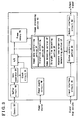
- the image processing device illustrated in Fig.1 includes an image processing means VA for generating a corrected captured image by use of a MMF model a captured image that is captured by the capturing means VD, and a displaying means DS for displaying an image which is captured by the capturing means VD and an image (corrected capture image) which the distortion of the capture image is corrected by use of the MMF model.
- the corrected captured image may be uses at a next process without displaying at the displaying means DS.
- the word "MMF model” comes from acronym for inventors of Morgan, Mercer and Flodin.
- the MMF model has been quoted in various documents, such as Non-patent document 5 described above, and also has been publicly known.
- the capturing means includes a camera having a distorted lens, and the captured image includes an image captured by the camera. Further, the distorted lens includes, for example, a wide-angle lens, and the capturing means VD includes, for example, a camera having the wide-angle lens.
- the image processing means VA may corrects an estimated image (e.g. an estimated locus EL of a movable body MB) by use of the MMF model and superimposed on a background image appearing within the captured image, which captured by the capturing means VD. Such image is displayed by the displaying means DS. Further, the image processing means VA may corrects an estimated image by use of the MMF model and superimposed on an object image indicating the environmental status, which appears within the captured image captured by the capturing means VD. Such image is displayed by the displaying means DS. "The object indicating the environmental status" represents an object to be detected, such as a driving lane or an obstacle, shown in the background image (scene image) captured by the capturing means.
- the capturing means VD is mounted on a movable body MB
- the image processing means VA includes an estimating means ES for generating an estimated locus EL of the movable body MB on the basis of an image captured by the capturing means VD.
- the estimated locus EL of the movable body represents an estimated locus EL that the movable body MB will be moved in a moving direction.
- the image processing means VA may corrects a geometrical shape, which generates the estimated locus EL estimated by the estimating means ES, by use of the MMF model, and the corrected estimated locus EL may be displayed on the displaying means DS.
- the geometrical shape represents a geometrical shape that includes a displayed position and a shape of the estimated locus EL The geometrical shape is used in order to display the estimated locus EL.
- Fig.19 illustrates the estimated locus EL, which is corrected to be distorted in accordance with the captured image, and displayed by the displaying means DS.
- Fig.3 illustrates another example in which the image processing device is applied to a detector for driving lane on road surface.
- a CCD camera hereinafter referred to as a camera CM
- a capturing means VD is attached to a front portion of a vehicle (not shown) in order to continuously capture a front view of the vehicle, including the road surface.
- the image signals from the camera CM is transmitted to a video input buffer circuit VB, and then transmitted to a sync separator SY. Further, the signals are converted from analog into digital and stored in the frame memory FM.
- the image data stored in the frame memory FM is processed in an image processing portion VC, and the image processing portion VC includes an image data controlling portion VP, a distortion correcting portion CP, an edge detecting portion EP, a straight line detecting portion SP and an adjacent lane borderline determining portion LP.
- the image processing portion VC From the image processing portion VC, data that is addressed by the image data controlling portion VP is read and transmitted to the distortion correcting portion CP.
- the data In the distortion correcting portion CP, the data is corrected.
- an edge is detected by means of, for example, a sobel operator, from the corrected image, and then coordinates of edge points in the image is extracted, the edge points corresponding to a border line of a white line on the road surface.
- straight line data is detected from the group of the edge points by applying a straight line to the edge points.
- a probable straight line that can be assumed as a position of the border of the lane is selected on the basis of a distance between the positions of the line and a physical relationship between the line and the vehicle, and such probable straight line is recognized as a road borderline, and thus, a driving lane borderline can be specified.
- the driving lane borderline includes not only that of the while line but also that of a guardrail or the like.
- an output from the adjacent lane borderline determining portion LP is transmitted to a system controlling portion SC (computer), and then the output is further transmitted to an external system device (not shown) by means of the output interface circuit OU.
- SC system controlling portion
- CL indicates a clock circuit
- PW indicate a power supply circuit
- IN indicates an input interface circuit.
- the distortion in the image can be corrected in the distortion correcting portion CP, shown in Fig.3, as follows.
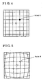
- a characteristic of the distorted image can be described as follows. Assuming that an optical center is a principal point, (white points in Fig.4 and Fig.5), and in Fig.6, a point of the object in the undistorted image (Fig.4) is indicated by a point A, and a point of the object in the distorted image (Fig.5) is indicated by a point B. Further, in Fig.6, a distance between the optical center and the point A is indicated by a distance D' and a distance between the optical center and the point B is indicated by a distance D. Generally a relationship between the distance D' and the distance D can be explained by some sort of a model formula.
- the distortion characteristic is corrected by means of a polynomial approximation.
- a test chart formed in a tetragonal lattice pattern is captured, a distorted image as shown in Fig.16A can be generally obtained.
- Fig.16B illustrates an ideal image in which a space between each line is equal.
- the lines in the ideal image are formed in a tetragonal lattice pattern that is similar to the tetragonal lattice pattern in the test chart.
- the more a part of the image at a point is located apart from the optical center of the image, in other words a optical center of the lens, the more the part of the image is distorted.
- a relationship between a distance D and a distance D' can indicated by the formula 1, the distance D indicating a distance between the optical center of the lens ( x 0 , y 0 ) and an optional pixcel ( x , y ) in the distorted image, and the distance D' indicating a distance between the optical center of the lens ( x 0 , y 0 ) and an optional pixcel ( X , Y ), which corresponds to the pixcel ( x,y ), in the ideal image.
- D ( x ⁇ x 0 ) 2 + ( y ⁇ y 0 ) 2
- D ′ ( X ⁇ X 0 ) 2 + ( Y ⁇ Y 0 ) 2
- D indicates a height of an actual image, specifically a distance between the optical center of the lens ( x 0 , y 0 ) and an optional pixcel ( x , y ) in the distorted image
- D ' indicates a height of an ideal image, specifically a distance between the optical center of the lens ( X 0 ,X 0 ) and an optional pixcel ( X,Y ) , which corresponds to the pixcel ( x , y ), in the actual image
- ⁇ D indicates an amount of the distortion.
- the distortion correcting coefficient can be obtained as follows. First, a coordinate of the lattice point in the distorted image of the test chart is measured in order to obtain the height D in the actual image. Second, the height D ' in the ideal image is set by a predetermined scale multiplication of the height D . Then, the coordinates of the lattice points in the distorted image is graphed as shown in Fig.17, and the coordinates of the lattice point in the ideal image is also graphed as shown in Fig.18. Further, the obtained distances D and D' are substitute into the formula 1, and the above fourth order polynomial is approximated by use of a least mean square, as a result, the distortion correcting coefficients a, b, c and d can be obtained.
- the distortion in the image can be corrected by means of polynomial approximation, however, when an image is captured by a wide-angle lens, the distortion in the image cannot be corrected sufficiency by means of polynomial approximation.
- Fig.7 and Fig.8 indicate results of polynomial approximation on the wide-angle lens design data formula. Specifically, Fig.4 illustrates a result in which the wide-angle lens design data formula is approximated by means of fourth order polynomial, and Fig.8 illustrates a result in which the wide-angle lens design data formula is approximated by means of tenth order polynomial.
- the order of the polynomial may be increased in order to reduce the errors upon the polynomial approximation.
- Fig.9 which illustrates an enlarged view of the wide-angle lens design data formula that is approximated by means of tenth polynomial
- the level of the residuals between the real value and an approximated curve is still high and also indicating a wave form.
- the distortion correcting portion CP corrects the distortion by means of not the above mentioned polynomial but the MMF model (Morgan-Mercer-Flodin Model).
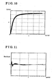
- An experimental result of the correction of the distortion in the wide-angle lens design data formula by use of the MMF model is shown in Fig.10, and Fig.11 illustrates an enlarged view of Fig.10.
- the distortion correcting portion CP in this embodiment it is clearly indicated that, comparing the result in Fig.11 to the result in Fig.8 and Fig.9, in which the wide-angle lens design data formula by use of the MMF model is accurately corrected than tenth order polynomial approximation, residuals between a real value and an approximated curve becomes small without enhancing a calculate amount.
- plural MMF models can be set and stored in the memory as a table, and an appropriate MMF model can be selected from them.
- Fig.12 and Fig.13 illustrates examples of experiment using a calibration chart having a tetragonal lattice pattern in a known size.
- the calibration chart includes a lattice pattern in a known three-dimension so that a relative position and dimension of each lattice can be shown in Fig.12 and Fig.13.
- a coordinate value of a lattice point shown in an image captured by a camera is detected, and on the basis of input information of a group of the lattice points and the three-dimension in the calibration chart, an inside parameter of the camera such as a magnification of a lens of a camera and a distortion coefficient can be calibrated.
- a polynomial model is applied in order to calculate an assumed distortion correction parameter, however, instead of the polynomial model, the MMF model is used in this embodiment.
- Fig.12 indicates residuals in the image when MMF model is used
- Fig.13 indicates residuals in the image when a polynomial approximation is applied.
- the residuals are represented in pixcels, which are enlarged twenty times. It is clear from Fig.12 and Fig.13 that the amount of the residuals is less in Fig.12, in which the MMF model is used, than the amount of the residuals in Fig.13.
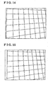
- Fig.14 illustrates a result in which the distorted input is corrected by use of the MMF model
- Fig.15 illustrates a result in which the distorted input is corrected by use of the polynomial approximation.
- a line that is supposed to be shown in a straight line is illustrated in a wavy line, which means that the level of the accuracy in the distortion correction is low.
- Fig.14 it can be observed that the level of the accuracy in the distortion correction is relatively high.
- the detector for driving lane on road surface employs the MMF model in order to correct the distortion coefficient of the camera lens
- the detector can recognize the white line on the road surface in a manner where an accuracy of detecting the road curvature can be enhanced, and further an accuracy of detecting the position of the vehicle relative to the white line and a postural relationship between the vehicle and the white line can also be enhanced.
- the parking assist device having the wide-angle lens employs the MMF model in order to correct the distortion coefficient of the camera lens
- the parking assist device superimposes the estimated locus EL of the vehicle in a rear direction
- the displayed trace and the estimated locus EL can be similar.
- the system for recognizing an obstacle employs the MMF model in order to correct the distortion coefficient of the camera lens, an accuracy in detecting a position, a size and a posture of the obstacle can be enhanced.
- the image processing device is mounted on the movable body such as a vehicle; however, it is not limited to such configuration.
- the image processing device can be applied to any device having, for example a device having a wide-angle lens and can also be applied to various kinds of image processing systems.
- the image processing method corrects the distortion in the image, which is captured by the capturing means, by use of the MMF model; the image processing such as the correction of the distortion can be appropriately conducted. For example, even when the image is captured by the capturing means such as a camera having a wide-angle lens, the distortion in the image can be appropriately corrected.
- the image processing method can appropriately conduct the image processing, for example, correcting the distortion in the image which is captured by the capturing means being mounted on the movable body.
- An image processing method processes a captured image, which is captured by a capturing means (VD, CM), characterized in that the image processing method comprises an image processing process (VA) for generating a corrected captured image by correcting a distortion appearing within the captured image by use of a MMF model.
- VD capturing means
- CM capturing means
- VA image processing process
Landscapes
- Physics & Mathematics (AREA)
- General Physics & Mathematics (AREA)
- Engineering & Computer Science (AREA)
- Theoretical Computer Science (AREA)
- Image Processing (AREA)
- Studio Devices (AREA)
- Image Analysis (AREA)
- Fittings On The Vehicle Exterior For Carrying Loads, And Devices For Holding Or Mounting Articles (AREA)
- Editing Of Facsimile Originals (AREA)
Applications Claiming Priority (1)
| Application Number | Priority Date | Filing Date | Title |
|---|---|---|---|
| JP2004313424A JP2006127083A (ja) | 2004-10-28 | 2004-10-28 | 画像処理方法及び画像処理装置 |
Publications (1)
| Publication Number | Publication Date |
|---|---|
| EP1655698A1 true EP1655698A1 (fr) | 2006-05-10 |
Family
ID=35976740
Family Applications (1)
| Application Number | Title | Priority Date | Filing Date |
|---|---|---|---|
| EP05023418A Withdrawn EP1655698A1 (fr) | 2004-10-28 | 2005-10-26 | Procédé et dispositif de traitement d'images |
Country Status (3)
| Country | Link |
|---|---|
| US (1) | US20060093239A1 (fr) |
| EP (1) | EP1655698A1 (fr) |
| JP (1) | JP2006127083A (fr) |
Families Citing this family (13)
| Publication number | Priority date | Publication date | Assignee | Title |
|---|---|---|---|---|
| JP2007124088A (ja) * | 2005-10-26 | 2007-05-17 | Olympus Corp | 画像撮影装置 |
| KR20080053834A (ko) * | 2006-12-11 | 2008-06-16 | 현대자동차주식회사 | 차량의 후방 카메라의 영상 왜곡 변환 방법 및 주차궤적표현 방법 |
| JP4872890B2 (ja) * | 2007-11-21 | 2012-02-08 | スズキ株式会社 | 画像の歪曲補正方法 |
| JP4937318B2 (ja) * | 2009-09-03 | 2012-05-23 | 株式会社東芝 | 画像処理装置及び画像調整方法 |
| WO2012120561A1 (fr) * | 2011-03-08 | 2012-09-13 | 三菱電機株式会社 | Appareil de correction d'image de périphérie d'objet en mouvement |
| JP6217227B2 (ja) * | 2013-08-12 | 2017-10-25 | 株式会社リコー | 校正装置、方法及びプログラム |
| US20150124120A1 (en) * | 2013-11-05 | 2015-05-07 | Microscan Systems, Inc. | Machine vision system with device-independent camera interface |
| CN103617615B (zh) * | 2013-11-27 | 2016-08-17 | 华为技术有限公司 | 径向畸变参数获取方法及获取装置 |
| EP3128747A4 (fr) * | 2014-04-03 | 2017-05-03 | Panasonic Intellectual Property Management Co., Ltd. | Dispositif de vérification de vue arrière et automobile équipée de ce dernier |
| CN105793892B (zh) * | 2014-12-09 | 2018-09-25 | 深圳市大疆创新科技有限公司 | 一种图像处理方法、装置及摄像设备 |
| US9930315B2 (en) * | 2015-04-29 | 2018-03-27 | Lucid VR, Inc. | Stereoscopic 3D camera for virtual reality experience |
| DE102018205399B4 (de) * | 2018-04-10 | 2021-03-18 | Continental Automotive Gmbh | Korrekturverfahren und Vorrichtung zur Korrektur von Bilddaten |
| CN112912332B (zh) * | 2018-10-16 | 2023-08-01 | 株式会社多田野 | 起重机装置 |
Citations (2)
| Publication number | Priority date | Publication date | Assignee | Title |
|---|---|---|---|---|
| US5675380A (en) * | 1994-12-29 | 1997-10-07 | U.S. Philips Corporation | Device for forming an image and method of correcting geometrical optical distortions in an image |
| WO2003043308A2 (fr) * | 2001-11-13 | 2003-05-22 | Koninklijke Philips Electronics N.V. | Procede de derivation d'un calibrage et procede de traitement des images |
Family Cites Families (8)
| Publication number | Priority date | Publication date | Assignee | Title |
|---|---|---|---|---|
| JPS6414700A (en) * | 1987-07-08 | 1989-01-18 | Aisin Aw Co | Device for displaying prospective track of vehicle |
| US4816586A (en) * | 1987-07-29 | 1989-03-28 | Regents Of The University Of Minnesota | Delta opioid receptor antagonists |
| US5223507A (en) * | 1992-01-21 | 1993-06-29 | G. D. Searle & Co. | Method of using opioid compounds as delta opioid selective agonist analgesics |
| JP2000125174A (ja) * | 1998-10-12 | 2000-04-28 | Fuji Photo Film Co Ltd | 画像情報における歪曲収差補正方法および装置 |
| JP3687516B2 (ja) * | 1999-01-19 | 2005-08-24 | 株式会社豊田自動織機 | 車両の後退時の操舵支援装置 |
| US6538691B1 (en) * | 1999-01-21 | 2003-03-25 | Intel Corporation | Software correction of image distortion in digital cameras |
| JP3668654B2 (ja) * | 1999-11-01 | 2005-07-06 | 株式会社大林組 | 歪曲収差の補正方法 |
| EP1564681A1 (fr) * | 2004-02-13 | 2005-08-17 | Dialog Semiconductor GmbH | Procédé pour la compensation de vignettage |
-
2004
- 2004-10-28 JP JP2004313424A patent/JP2006127083A/ja active Pending
-
2005
- 2005-10-26 EP EP05023418A patent/EP1655698A1/fr not_active Withdrawn
- 2005-10-27 US US11/259,079 patent/US20060093239A1/en not_active Abandoned
Patent Citations (2)
| Publication number | Priority date | Publication date | Assignee | Title |
|---|---|---|---|---|
| US5675380A (en) * | 1994-12-29 | 1997-10-07 | U.S. Philips Corporation | Device for forming an image and method of correcting geometrical optical distortions in an image |
| WO2003043308A2 (fr) * | 2001-11-13 | 2003-05-22 | Koninklijke Philips Electronics N.V. | Procede de derivation d'un calibrage et procede de traitement des images |
Non-Patent Citations (4)
| Title |
|---|
| ALAMUS R. ET AL.: "On the Accuracy and Performance of the Geomobil System", ISPRS 2004, 12 July 2004 (2004-07-12) - 23 July 2004 (2004-07-23), Istanbul, Turkey, XP002372167 * |
| REIS DOS SANTOS M.I. AND PORTA NOVA A.M.O.: "Statistical fitting and validation of non-linear simulation metamodels: A case study", EUROPEAN JOURNAL OF OPERATIONAL RESEARCH (PREPRINT), 4 October 2004 (2004-10-04), XP002372169 * |
| TJORVE E.: "SHAPES AND FUNCTIONS OF SPECIES-AREA CURVES: A REVIEW OF POSSIBLE MODELS", JOURNAL OF BIOGEOGRAPHY, vol. 30, 2003, pages 827 - 835, XP002372170 * |
| ZHANG Z.: "A Flexible New Technique for Camera Calibration", MICROSOFT RESEARCH TECHNICAL REPORT MSR-TR-98-71, 2 December 1998 (1998-12-02), XP002372168 * |
Also Published As
| Publication number | Publication date |
|---|---|
| JP2006127083A (ja) | 2006-05-18 |
| US20060093239A1 (en) | 2006-05-04 |
Similar Documents
| Publication | Publication Date | Title |
|---|---|---|
| KR101969030B1 (ko) | 차량용 카메라 캘리브레이션 장치 및 그 방법 | |
| KR100869570B1 (ko) | 카메라 교정 방법 및 카메라 교정 장치 | |
| EP2128821B1 (fr) | Dispositif de reconnaissance d'objet en mouvement | |
| US20190356830A1 (en) | Image distortion correction of a camera with a rolling shutter | |
| US20220254064A1 (en) | External parameter calibration method, device and system for image acquisition apparatus | |
| JP4406381B2 (ja) | 障害物検出装置及び方法 | |
| US8126210B2 (en) | Vehicle periphery monitoring device, vehicle periphery monitoring program, and vehicle periphery monitoring method | |
| CN102792333B (zh) | 图像处理装置、方法、程序以及记录介质 | |
| EP2009590B1 (fr) | Dispositif d'assistance à la conduite | |
| EP1640912B1 (fr) | Appareil pour déterminer la hauteur d'un objet mobile | |
| EP1655698A1 (fr) | Procédé et dispositif de traitement d'images | |
| US20120314073A1 (en) | Apparatus and Method for Detecting Posture of Camera Mounted on Vehicle | |
| CN108141570A (zh) | 校准装置、校准方法以及校准程序 | |
| CN101419667A (zh) | 识别图像中障碍物的方法和装置 | |
| JPWO2015015542A1 (ja) | 車載ステレオカメラシステム及びそのキャリブレーション方法 | |
| KR101482645B1 (ko) | Fov왜곡 보정 모델에 2d패턴을 적용한 왜곡중심 보정 방법 | |
| JP2014074632A (ja) | 車載ステレオカメラの校正装置及び校正方法 | |
| EP1828979B1 (fr) | Procédé pour déterminer la position d'un objet à partir d'une image numérique | |
| EP3435327A1 (fr) | Dispositif de détection de l'état de la surface d'une route | |
| US8044998B2 (en) | Sensing apparatus and method for vehicles | |
| JP7380443B2 (ja) | 部分画像生成装置及び部分画像生成用コンピュータプログラム | |
| CN107545775B (zh) | 用于显示停车区域的装置和方法 | |
| JP4735361B2 (ja) | 車両乗員顔向き検出装置および車両乗員顔向き検出方法 | |
| JPWO2017042995A1 (ja) | 車載用ステレオカメラ装置、およびその補正方法 | |
| JP5049304B2 (ja) | 車両の周辺を画像表示するための装置 |
Legal Events
| Date | Code | Title | Description |
|---|---|---|---|
| PUAI | Public reference made under article 153(3) epc to a published international application that has entered the european phase |
Free format text: ORIGINAL CODE: 0009012 |
|
| AK | Designated contracting states |
Kind code of ref document: A1 Designated state(s): AT BE BG CH CY CZ DE DK EE ES FI FR GB GR HU IE IS IT LI LT LU LV MC NL PL PT RO SE SI SK TR |
|
| AX | Request for extension of the european patent |
Extension state: AL BA HR MK YU |
|
| 17P | Request for examination filed |
Effective date: 20061108 |
|
| AKX | Designation fees paid |
Designated state(s): DE FR |
|
| STAA | Information on the status of an ep patent application or granted ep patent |
Free format text: STATUS: THE APPLICATION IS DEEMED TO BE WITHDRAWN |
|
| 18D | Application deemed to be withdrawn |
Effective date: 20100504 |