EP1655820A2 - Système magnétique intégre de lévitation et de rotation - Google Patents
Système magnétique intégre de lévitation et de rotation Download PDFInfo
- Publication number
- EP1655820A2 EP1655820A2 EP06001269A EP06001269A EP1655820A2 EP 1655820 A2 EP1655820 A2 EP 1655820A2 EP 06001269 A EP06001269 A EP 06001269A EP 06001269 A EP06001269 A EP 06001269A EP 1655820 A2 EP1655820 A2 EP 1655820A2
- Authority
- EP
- European Patent Office
- Prior art keywords
- rotor
- stator assembly
- magnetic
- coils
- axis
- Prior art date
- Legal status (The legal status is an assumption and is not a legal conclusion. Google has not performed a legal analysis and makes no representation as to the accuracy of the status listed.)
- Withdrawn
Links
Images


Classifications
-
- H—ELECTRICITY
- H02—GENERATION; CONVERSION OR DISTRIBUTION OF ELECTRIC POWER
- H02K—DYNAMO-ELECTRIC MACHINES
- H02K7/00—Arrangements for handling mechanical energy structurally associated with dynamo-electric machines, e.g. structural association with mechanical driving motors or auxiliary dynamo-electric machines
- H02K7/08—Structural association with bearings
-
- H—ELECTRICITY
- H10—SEMICONDUCTOR DEVICES; ELECTRIC SOLID-STATE DEVICES NOT OTHERWISE PROVIDED FOR
- H10P—GENERIC PROCESSES OR APPARATUS FOR THE MANUFACTURE OR TREATMENT OF DEVICES COVERED BY CLASS H10
- H10P72/00—Handling or holding of wafers, substrates or devices during manufacture or treatment thereof
- H10P72/70—Handling or holding of wafers, substrates or devices during manufacture or treatment thereof for supporting or gripping
- H10P72/76—Handling or holding of wafers, substrates or devices during manufacture or treatment thereof for supporting or gripping using mechanical means, e.g. clamps or pinches
- H10P72/7604—Handling or holding of wafers, substrates or devices during manufacture or treatment thereof for supporting or gripping using mechanical means, e.g. clamps or pinches the wafers being placed on a susceptor, stage or support
- H10P72/7626—Handling or holding of wafers, substrates or devices during manufacture or treatment thereof for supporting or gripping using mechanical means, e.g. clamps or pinches the wafers being placed on a susceptor, stage or support characterised by the construction of the shaft
-
- F—MECHANICAL ENGINEERING; LIGHTING; HEATING; WEAPONS; BLASTING
- F16—ENGINEERING ELEMENTS AND UNITS; GENERAL MEASURES FOR PRODUCING AND MAINTAINING EFFECTIVE FUNCTIONING OF MACHINES OR INSTALLATIONS; THERMAL INSULATION IN GENERAL
- F16C—SHAFTS; FLEXIBLE SHAFTS; ELEMENTS OR CRANKSHAFT MECHANISMS; ROTARY BODIES OTHER THAN GEARING ELEMENTS; BEARINGS
- F16C32/00—Bearings not otherwise provided for
- F16C32/04—Bearings not otherwise provided for using magnetic or electric supporting means
- F16C32/0406—Magnetic bearings
- F16C32/044—Active magnetic bearings
- F16C32/0444—Details of devices to control the actuation of the electromagnets
- F16C32/0446—Determination of the actual position of the moving member, e.g. details of sensors
- F16C32/0448—Determination of the actual position of the moving member, e.g. details of sensors by using the electromagnet itself as sensor, e.g. sensorless magnetic bearings
-
- F—MECHANICAL ENGINEERING; LIGHTING; HEATING; WEAPONS; BLASTING
- F16—ENGINEERING ELEMENTS AND UNITS; GENERAL MEASURES FOR PRODUCING AND MAINTAINING EFFECTIVE FUNCTIONING OF MACHINES OR INSTALLATIONS; THERMAL INSULATION IN GENERAL
- F16C—SHAFTS; FLEXIBLE SHAFTS; ELEMENTS OR CRANKSHAFT MECHANISMS; ROTARY BODIES OTHER THAN GEARING ELEMENTS; BEARINGS
- F16C32/00—Bearings not otherwise provided for
- F16C32/04—Bearings not otherwise provided for using magnetic or electric supporting means
- F16C32/0406—Magnetic bearings
- F16C32/044—Active magnetic bearings
- F16C32/047—Details of housings; Mounting of active magnetic bearings
-
- F—MECHANICAL ENGINEERING; LIGHTING; HEATING; WEAPONS; BLASTING
- F16—ENGINEERING ELEMENTS AND UNITS; GENERAL MEASURES FOR PRODUCING AND MAINTAINING EFFECTIVE FUNCTIONING OF MACHINES OR INSTALLATIONS; THERMAL INSULATION IN GENERAL
- F16C—SHAFTS; FLEXIBLE SHAFTS; ELEMENTS OR CRANKSHAFT MECHANISMS; ROTARY BODIES OTHER THAN GEARING ELEMENTS; BEARINGS
- F16C32/00—Bearings not otherwise provided for
- F16C32/04—Bearings not otherwise provided for using magnetic or electric supporting means
- F16C32/0406—Magnetic bearings
- F16C32/044—Active magnetic bearings
- F16C32/0474—Active magnetic bearings for rotary movement
- F16C32/0493—Active magnetic bearings for rotary movement integrated in an electrodynamic machine, e.g. self-bearing motor
-
- H—ELECTRICITY
- H02—GENERATION; CONVERSION OR DISTRIBUTION OF ELECTRIC POWER
- H02K—DYNAMO-ELECTRIC MACHINES
- H02K19/00—Synchronous motors or generators
- H02K19/02—Synchronous motors
- H02K19/10—Synchronous motors for multi-phase current
-
- H—ELECTRICITY
- H02—GENERATION; CONVERSION OR DISTRIBUTION OF ELECTRIC POWER
- H02K—DYNAMO-ELECTRIC MACHINES
- H02K21/00—Synchronous motors having permanent magnets; Synchronous generators having permanent magnets
- H02K21/38—Synchronous motors having permanent magnets; Synchronous generators having permanent magnets with rotating flux distributors, and armatures and magnets both stationary
- H02K21/44—Synchronous motors having permanent magnets; Synchronous generators having permanent magnets with rotating flux distributors, and armatures and magnets both stationary with armature windings wound upon the magnets
-
- H—ELECTRICITY
- H02—GENERATION; CONVERSION OR DISTRIBUTION OF ELECTRIC POWER
- H02K—DYNAMO-ELECTRIC MACHINES
- H02K7/00—Arrangements for handling mechanical energy structurally associated with dynamo-electric machines, e.g. structural association with mechanical driving motors or auxiliary dynamo-electric machines
- H02K7/08—Structural association with bearings
- H02K7/09—Structural association with bearings with magnetic bearings
-
- F—MECHANICAL ENGINEERING; LIGHTING; HEATING; WEAPONS; BLASTING
- F16—ENGINEERING ELEMENTS AND UNITS; GENERAL MEASURES FOR PRODUCING AND MAINTAINING EFFECTIVE FUNCTIONING OF MACHINES OR INSTALLATIONS; THERMAL INSULATION IN GENERAL
- F16C—SHAFTS; FLEXIBLE SHAFTS; ELEMENTS OR CRANKSHAFT MECHANISMS; ROTARY BODIES OTHER THAN GEARING ELEMENTS; BEARINGS
- F16C2380/00—Electrical apparatus
- F16C2380/26—Dynamo-electric machines or combinations therewith, e.g. electro-motors and generators
-
- H—ELECTRICITY
- H02—GENERATION; CONVERSION OR DISTRIBUTION OF ELECTRIC POWER
- H02K—DYNAMO-ELECTRIC MACHINES
- H02K17/00—Asynchronous induction motors; Asynchronous induction generators
- H02K17/02—Asynchronous induction motors
- H02K17/12—Asynchronous induction motors for multi-phase current
Definitions
- This invention relates in general to magnetic bearings and electromagnetic motors. More specifically, it relates to a process and apparatus providing an integrated, highly compact, integrated rotary magnetic bearing and motor particularly one useful in semiconductor wafer processing.
- RTP rapid thermal processing
- Uniformity of processing over the entire wafer is important because the wafer is eventually subdivided into multiple discrete devices, e.g., microprocessor or memory chips, that each must have generally the same known characteristics. Uniformity is also important where it is desired to use a relatively large surface area for a single device, e.g., fabrication of an entire computer on a single chip. In short, uniformity also influences yield. To produce uniformity, it is conventional to rotate the wafer about a vertical or z-axis perpendicular to, and centered on, the wafer as it is being processed. Rotation is also used for other wafer processing such as chemical vapor deposition, heat treatment, doping by ion implantation, and doping by other techniques.
- Bearing failure is the cause of significant production down-time. It also raises manufacturing costs due to the direct cost of new bearings and often the loss of a wafer being processed, which may itself have a value in the range of $50,000. Even without bearing failure, wafers break. Besides the loss of the wafer, breakage also produces a significant loss of production time since any wafer break produces wafer fragments and particles which must be meticulously cleaned out of the bearings before the chamber can be used again.
- mechanical bearings When operating, mechanical bearings also produce vibration (they are noisy) and they transmit, and can be worn or damaged by, external mechanical shock and vibration. Mechanical bearings also suffer from stiction and "play" which introduce error in position control which adversely affect quality and yield.
- Magnetic handling has been considered for use in wafer processing.
- M. Ota et al. in “Development Of Mag-Lev Polar Coordinate Robot Operation in Ultra High Vacuum", Magnetic Suspension II, pp. 351-359 (1991) describe a polar coordinate robot for operation in a vacuum using magnetic bearings.
- Magnetic bearings for contactless suspension and linear movement of wafers is also the subject of papers such as S. Moriyama et al., “Development of Magnetically Suspended Linear Pulse Motor for Contactless Direct Drive in Vacuum Chamber Robot", Kyushu Institute of Technology, Transaction of the Institute of Electrical Engineers of Japan, Vol. 115-D, No. 3, March 1995, pp. 311-318. While the advantages of magnetic suspensions to avoid of contamination problems of mechanical bearings are clear cut, this kind of research has been limited to wafer transport, particularly linear wafer transport between process chambers, not for use in a chamber itself to rotate the wafer during processing.
- Magnetic bearings both radial and axial, are also used in devices as diverse as gyroscopes, flywheels, gas turbines, and electrical measuring instruments.
- this passive control uses magnetic repulsion between a pair of permanent magnets arrayed along one axis.
- LC tuned circuits are also known to vary a magnetic field generating current in a coil of inductance value L in a manner which provides a passive control.
- the coil inductance L and a capacitor with a value C are series coupled.
- An A.C. excitation frequency is set just above the LC resonant frequency. Because the inductance of the coil is very sensitive to the air gap between the coil and the rotor, changes in the gap automatically produce changes in the impedance of the LC circuit, which in turn adjusts the current flow to induce a centering.
- a driven rotating member if a driven rotating member is magnetically supported, it must also be driven.
- a direct mechanical drive there is the problem of how to transmit the rotary power into a chamber without a frictional contact that is open to the chamber (a source of contaminants) while maintaining a controlled atmosphere within the chamber (e.g. a rotating shaft held in a seal).
- a magnetic drive can overcome this problem, but it introduces the bulk and cost of this type of drive, as well as further problems such as the interaction of an AC flux of the drive with a DC flux of the suspension.
- the AC drive flux produces further complications.
- the AC flux produces eddy current losses in the chamber wall as well as losses in the stator and rotor.
- the air gap that accommodates the chamber wall constitutes a significant source of reluctance in the magnetic circuit.
- the AC flux acting on the rotor competes with the substantial saturation of the rotor by the DC suspension flux. In short, there are significant design consideration that lead away from integrating a rotary magnetic drive with a magnetic suspension.
- a further principal object of this invention is to provide such an integrated magnetic bearing and drive process and apparatus which are highly compact, both physically and in the active control needed to establish and maintain the bearing gap.
- Another object is to provide an integrated magnetic bearing and drive with the foregoing advantages which can operate reliably and with a long life in a vacuum, in a corrosive atmosphere, or at high temperatures such as those encountered in wafer processing, particularly RTP processing.
- a further object is to provide an integrated magnetic bearing and drive with the foregoing advantages which can process very large diameter (e.g., >300 mm diameter) wafers and rotate them at over speed ranges from 50 to 1200 rpm.
- very large diameter e.g., >300 mm diameter
- a still further object is to provide a magnetic bearing and drive for wafer processing which reduces the particulate contaminants in the chamber and production down-time due to particle contamination or mechanical bearing failure.
- Another object is to provide an integrated magnetic bearing and drive which allows a high degree of precision in positioning, produces no vibration, and isolates the wafer from external vibration and shock.
- Still another object is to provide these advantages with a competitive cost of manufacture.
- a compact, integrated magnetic levitation and rotational drive utilizes a magnetic rotor and a surrounding, non-contacting stator assembly.
- the stator assembly has a permanent magnet or other source of DC magnetic flux sandwiched between mutually vertically spaced pole pieces, preferably plates, of a ferromagnetic material with a low reluctance.
- the plates are preferably divided into plural equangularly spaced pole segments, e.g. four segments, that closely surround the rotor with an annular air gap.
- the rotor is preferably a ring with a complementary set of poles, e.g., eight doubly salient sets of pole teeth, formed on its outer periphery and positioned vertically between the stator plates.
- This arrangement uses the flux of the permanent magnet to (i) passively center the rotor along a vertical z-axis, (ii) radially bias the x-y position of the rotor within the stator assembly in a horizontal, x-y plane, and (iii) provide a flux field in the rotor poles which can interact with a rotating field established by suitably energized polyphase motor windings on the stator assembly.
- Each stator pole segment carries active position control coils that are preferably wound between arcuate slots in the body of each stator plate.
- the radial, vertical, and angular positions of the rotor are sensed with eddy current and Hall effect or equivalent sensors positioned proximate the rotor.
- Closed-loop feedback control circuits of a controller produce currents that energize the control coils to produce a magnetic flux that adds or subtracts from the DC flux field produced by the permanent magnet. The currents adjust the flux field strength to maintain the rotor in a radially centered x-y position.
- out-of-plane vibrations are controlled solely by passive means such as inter connection of coils and selection of materials such that these vibrations cause eddy currents to be generated which damp the oscillations.
- An alternative form of the invention use a toothless rotor to provide an asynchronous induction motor.
- Alternative passive radial position controls use capacitors in series with the active control coils and AC excitation of the LC circuit set just above its resonant frequency. Charges in the stator-to-rotor air gap couple to the coil to produce changes in the inductance L of the coil, which causes the current to vary in a manner that drives the rotor toward the desired centered position.
- Position sensing can also be estimated.
- a small signal is superposed on the control coil current at a high carrier frequency to monitor the air gap in the magnetic circuit.
- Another position estimation method measures the control coil current directly.
- a microprocessor analyzes the sensed coil current to yield radial position information.
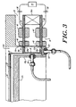
- Figs. 1-4 show an integrated magnetic motoring and suspension system (IMMSS) 10 according to the present invention adapted for use in conjunction with a sealed chamber 12 for processing silicon wafers 14 into multiple discrete semiconductor devices such as microprocessors or memory chips.
- the IMMSS 10 features a stator assembly 16 that surrounds a rotor 18 with a radial spacing, a thin annular air gap 20.
- the rotor 18 supports, and is replaceably coupled to, a wafer carrier 22, which in turn carries the wafer 14 on its upper surface.
- the rotation of the rotor about a vertical z-axis 24 rotates the carrier 12 and wafer 14 about the same z-axis, which during operation is generally coincident with a common centerline of the rotor, carrier, and wafer. Rotation of these elements is preferably constrained to lie a single horizontal x,y plane where the x-axis 26, y-axis 28 and z-axis 24 are mutually orthogonal.
- the invention will be described herein with reference to its present principal application, the successive processing of multiple wafers 14 in the chamber 12, and in particular, a rapid thermal processing (RTP) of the wafer 14 to relieve crystal lattice strain produced by dopant ion implantation.
- RTP rapid thermal processing
- the invention is useful in other semiconductor processing steps where it is necessary or desirable to rotate a wafer in a controlled or hostile environment, or more broadly, whenever it is required to rotate and suspend a body, particularly where the body is in a controlled atmosphere.
- the RTP chamber 12 has a lower housing 12a and an upper housing cover 12b that mate in a seal sufficient to maintain a vacuum within the chamber (e.g. 0.001 Torr), but also separate to allow direct access to the interior of the chamber as necessary. Screws 30 secure that stator assembly 16 to a wall 12c of the chamber housing 12a.
- the rotor 18 is received in an annular well 12d formed by a cylindrical chamber wall 12e, a bottom flange 12f, and a cylindrical wall 12g capped by a circular bottom plate 12h which underlies the wafer carrier 22 with a clearance 32.
- This geometry allows a simple drop-in insertion and removal of the rotor 18 from the chamber, which, because the rotor is ferromagnetic, can be performed magnetically using robotics, or manually. If there is a wafer break, removal of the rotor 18, carrier 22, and the remains of the wafer 14 leaves only smooth surfaces that can be readily cleaned of wafer particles in a small fraction of the time required to clean conventional mechanical bearing assemblies. This geometry also leaves access to the wafer, wafer carrier, and the wafer unobstructed from above and below. This is important in establishing a well defined thermal gradient across the wafer using a lamp 34, or equivalent source of radiant thermal energy, under the control of one or more optical pyrometers 35, or the like, mounted in the housing portion 12h. This geometry is also highly compatible with a fully robotic, fully integrated magnetic handling and transport system which positions the wafer and/or its carrier and transports it or them to and from other processing stations.
- the wall 12e in the annular gap 20 must be thin, non-magnetic and not introduce significant eddy current losses.
- the wall 12e is preferably 0.035 inch thick and formed of type 316 stainless steel.
- the other chamber walls are also preferably formed of the same material.
- the stator assembly 16 has a pair of vertically spaced pole pieces 36, 36 in the form of generally flat plates that sandwich a permanent magnet 38, which, as shown, is preferably four identical, equiangularly-spaced permanent magnets 38a, each associated with, and angularly centered on, a pole segment 36a.
- the four magnets 38a are mounted generally at the outer periphery of the plates 36, 36. They are capable of producing a strong DC magnetic flux field at the rotor despite the presence of air gaps. The DC flux field is strong enough to levitate the rotor and stiffly center it vertically.
- Magnets of samarium cobalt, various grades of neodymium boron iron, and ceramics are suitable. Ceramic ferrite magnets are preferred for low cost. Samarium cobalt may be used where the operating temperature range and demagnetization are concerns. Neodymium offers the most magnetic flux for a given size.
- the plates 36,36 are formed of a magnetic material with a high magnetic permeability and a corresponding low reluctance. Low carbon steel is preferred due to its low cost.
- the high reluctance air gaps between the rotor and stator plates are minimized by forming two radially outward extending flanges 18a and 18b on the rotor. They are mutually spaced in the vertical direction so that they each can align generally with one of the plates 36.
- the rotor is also formed of a ferromagnetic material with a high magnetic permeability and corresponding low reluctance.
- the rotor is a ring of low carbon steel with a nickel plating.
- silicon steel can be used for lower reluctance or 17-4PH stainless steel for higher corrosion resistance.
- the DC flux set up by the permanent magnet 38 and its pole pieces 36, 36 induces a magnetic flux field in the rotor of opposite polarity, much as a permanent magnet magnetizes a nearby soft iron member with an opposite polarity, causing them to be drawn toward one another (and thereby minimizing the intervening air gap, which reduces the reluctance of the magnetic circuit).
- the stator assembly 16 and rotor 18 are constructed to utilize this tendency to minimize the circuit reluctance to close the air gaps 22a and 22b between the upper and lower plates 36 and the flanges 18a and 18b respectively.
- the magnetic forces in these air gaps are analogous to a pair opposed mechanical springs that combine produce a leveling effect as well as the levitation of the rotor.
- the rotor flanges each have eight poles 18c sized and spaced to match the four stator poles segment 36a, as shown in Fig. 1. Because there are two flanges 18a and 18b, poles 18c are formed in a matching pattern on both flanges to produce a like saliency.
- the DC flux of the permanent magnet also produces an attractive magnetic force between the poles of the stator and the rotor. This attractive force is radially directed and establishes a radial bias. However, it is unstable and tends to pull the rotor radially to one side. Additional radial positions controls are therefore necessary, as will be discussed below. It is also important that the DC magnetic flux of the permanent magnet 38, by magnetizing the rotor and its pole teeth, also induces a rotor flux field. The rotor field interacts with a rotating electromagnetic field to develop a torque about the z-axis, and thereby drive the rotor.
- the stator assembly includes two sets of coils, a drive coil 40 and multiple active control coils 42 each associated with one plate of one of the pole segments 36a.
- the drive coil 40 is preferably a polyphase winding with end windings held in a series of notches 44 formed on the inner edges of the stators plates 36,36.
- the drive winding 40 is energized by a conventional multiphase AC drive current to develop a rotating electromagnetic field that interacts with the DC magnetic flux field of the rotor to cause it to rotate.
- the control coils 42 are eight in number, each wound on one of the upper and lower plates 36,36 through body-centered arcuate slots 46 that are also angularly centered on radial slots 48 that separate and define the stator poles segments 36a.
- the control coils 42 each carry a control current that produces a magnetic flux. Depending on the direction of the current, this flux adds or subtracts from (modulates) the DC magnetic field acting on the rotor. Coordinated adjustments in these currents stabilize the radial position and orientation of the rotor, both static and dynamic.
- the radially centered rotor position leaves a clearance on both sides of the rotor so that there is no frictional contact with the chamber walls as it rotates. The aforementioned levitation raises the rotor from the flange 12f at the bottom of the well 12d.
- control coils 42 energized in a "push-pull" manner in a vertically spaced pairs as well as on diametrically opposite sides of the rotor maximize control over such oscillations, or any deviations of the rotor from the preselected vertical position and preselected horizontal orientation.
- radial positions sensors 48, four vertical position sensors 50, and three commutation sensors 52 are mounted proximate the rotor in the side chamber wall 12g, bottom flange 12f, and on the inner periphery of the pole pieces 36, 36 respectively.
- the position sensors are standard eddy current sensors, or known equivalents. They produce signals which correspond to the physical position, radial and vertical, of the rotor.
- the commutation sensors 52 are standard Hall effect sensors; they sense the angular position of the rotor as determined by the presence or absence of a tooth 18c. Angular position is used for conventional electronic commutation of the drive windings 40.
- the sensors 52 are preferably mounted in alternate notches 44 in the pole plate 36,, over the drive winding 40 in that notch. Radial and vertical position information is input to a controller 54 which produces output currents to each of the position control coils 42.
- a controller 54 which produces output currents to each of the position control coils 42.
- the lines connecting the sensors and coils to the controller 54 are shown in Fig. 1 only with respect to one coil 42 and two sensors 48 and 50. However, it will be understood that output signals from all sensors 48 and 50 are supplied ass inputs to the controller 54.
- the controller 54 is preferably Texas Instruments model DSP C3O controller, by or any of a variety of equivalent devices well known to those skilled in the art.
- the magnitude and direction of the current applied to the associated coils 42 produces a modulation of the flux field at the rotor which (i) actively radially centers the rotor. Because three degrees of freedom -- position along the z-axis and rotation about x and y axes -- are controlled passively, the cost and bulk of the active control circuiting is reduced substantially as compared to a system of total active control in all degrees of freedom.
- the control current can also actively control tip and tilt out of a preselected x-y plane, and in particular damp oscillations which appear at high rotational speeds and which the passive vertical centering of the DC magnetic flux is not able to control adequately.
- the rotor has a weight of about 5.5 pounds (2.5 kg).
- a quartz ring carrier 22 and wafer 14 have a weight of 2.0 pounds for a total weight of 7.5 pounds (3.4kg) to be levitated, centered and rotated.
- the rotor is suspended with a vertical stiffness of about 200 lbs./inch.
- the control coil 42 has a maximum power rating of 18 watts per axis.
- the running power is about 1 watt per axis.
- this IMSS develops a maximum torque of 3.0 Nm with a maximum rotational speed of 1200 rpm, taking about 6.0 seconds to spin up to operating speed from a standstill.
- Maximum motor power at spin up is 200 watts, and the power at normal operating speed is estimated at about 100 watts, which in part reflects eddy current losses.
- a capacitor 56 (shown in phantom) is connected in series with each radial control coil 42.
- a fixed amplitude, fixed frequency A.C. voltage excites the circuit.
- f n the impedance of the LC circuit is purely ohmic, and the current in the coils is therefore large.
- Limitations of this approach include increased power losses in the chamber wall due to the eddy currents set up by the AC excitation, interference with the AC motoring excitement of the drive coil 40, limited flexibility in tailoring the system dynamics, and reduced damping capabilities.
- Another alternative to radial position control one which eliminates the sensors, but not the controller, is position estimation.
- One method superposes a small signal as a high carrier frequency on the control coil current. This high frequency signal provides a measure of the impedance (as discussed above with respect to the LC circuit), which in turn is a measure of the air gap in the magnetic circuit, and hence of the position of the rotor.
- a second method directly measures the current in the control coils 42.
- the sensed current value is a function of the inductive impedance of the associated coil 42, which in turn is a function of the magnitude of the air gap 22.
- a micropressor in the controller is programmed to translate the sensed current changes into rotor position changes. The controller then uses this position information in the usual way to make the appropriate corrections in the control coil currents to drive the rotor to a pre-selected position and orientation.
- "sensing” is mean to include position sensing using transducers as well as the LC and estimation approaches described herein and other techniques known to those skilled in the art.
- position control is totally passive to avoid the cost of sensors and active control electronics. Total passive control works well for sufficiently low rotational speeds, but for operation high speeds, e.g. 1200 rpm, some degree of active control is preferred.
- the IMMSS 10 is also possible to use the IMMSS 10 with an induction motor. This allows the system to operate off a fixed frequency and excitation voltage. It also eliminates the proximity sensors 52 and electronic commutators for the phase currents of the homopolar motor. Further, an induction motor avoids the torque fluctuations produced by the poles of the homopolar motor.
- the IMMSS 10 is able to operate as an asynchronous induction motor simply by removing the rotor teeth 18c, as shown in phantom in Fig. 4.
- the problem of an induction drive is the strong AC field necessary to spin up to normal operation at the fixed frequency.
- the integration lends itself to a high degree of compactness which is necessary for a commercially practical IMMSS.
- the IMMSS of the invention reduces wafer production down-time due to bearing failure and to clean up associated with wafer breaks and bearing failure. It is also highly compatible with robotics that can provide fully integrated, contact-less wafer fabrication. It also allows the processing of larger diameter (e.g. >300mm) wafers and at higher rotational speeds (e.g. 1200 rpm) than heretofore possible with conventional equipment using mechanical bearings.
- the system described herein is also highly flexible. It can handle different rotated bodies (wafer, non-wafers, wafers of varying sizes), different operating environments, a range of rotational speeds, and a wide range of other cost/performance trade-offs.
- poles which carry the flux across a small air gap to the rotor so that the flux simultaneously performs the levitation, radial biasing and rotor flux field magnetization functions described above.
- field coils and control coils are described as end- wound and centrally-wound, respectively, other locations for these windings are possible.
- the control coils should be directly coupled with the DC magnetic circuit.
- the stator and rotor can also be laminated to control eddy current losses, but with attendant increases in cost.
- the rotor can be formed with a different number of poles, single salient pole teeth, or, as described above with respect to an asynchronous inductive motor, with no pole teeth.
Landscapes
- Engineering & Computer Science (AREA)
- General Engineering & Computer Science (AREA)
- Power Engineering (AREA)
- Mechanical Engineering (AREA)
- Physics & Mathematics (AREA)
- Electromagnetism (AREA)
- Magnetic Bearings And Hydrostatic Bearings (AREA)
- Container, Conveyance, Adherence, Positioning, Of Wafer (AREA)
- Synchronous Machinery (AREA)
- Induction Machinery (AREA)
- Connection Of Motors, Electrical Generators, Mechanical Devices, And The Like (AREA)
Applications Claiming Priority (2)
| Application Number | Priority Date | Filing Date | Title |
|---|---|---|---|
| US08/548,692 US5818137A (en) | 1995-10-26 | 1995-10-26 | Integrated magnetic levitation and rotation system |
| EP96936771A EP0876702B1 (fr) | 1995-10-26 | 1996-10-18 | Systeme magnetique integre de levitation et de rotation |
Related Parent Applications (1)
| Application Number | Title | Priority Date | Filing Date |
|---|---|---|---|
| EP96936771A Division EP0876702B1 (fr) | 1995-10-26 | 1996-10-18 | Systeme magnetique integre de levitation et de rotation |
Publications (2)
| Publication Number | Publication Date |
|---|---|
| EP1655820A2 true EP1655820A2 (fr) | 2006-05-10 |
| EP1655820A3 EP1655820A3 (fr) | 2006-07-05 |
Family
ID=24189988
Family Applications (2)
| Application Number | Title | Priority Date | Filing Date |
|---|---|---|---|
| EP06001269A Withdrawn EP1655820A3 (fr) | 1995-10-26 | 1996-10-18 | Système intégré de lévitation et de rotation magnétique |
| EP96936771A Expired - Lifetime EP0876702B1 (fr) | 1995-10-26 | 1996-10-18 | Systeme magnetique integre de levitation et de rotation |
Family Applications After (1)
| Application Number | Title | Priority Date | Filing Date |
|---|---|---|---|
| EP96936771A Expired - Lifetime EP0876702B1 (fr) | 1995-10-26 | 1996-10-18 | Systeme magnetique integre de levitation et de rotation |
Country Status (8)
| Country | Link |
|---|---|
| US (2) | US5818137A (fr) |
| EP (2) | EP1655820A3 (fr) |
| JP (1) | JP4165903B2 (fr) |
| KR (1) | KR100423366B1 (fr) |
| CA (1) | CA2233707C (fr) |
| DE (1) | DE69635841T2 (fr) |
| MX (1) | MX9803156A (fr) |
| WO (1) | WO1997015978A1 (fr) |
Cited By (5)
| Publication number | Priority date | Publication date | Assignee | Title |
|---|---|---|---|---|
| WO2008074574A1 (fr) | 2006-12-19 | 2008-06-26 | Robert Bosch Gmbh | Machine électrique |
| WO2016207492A1 (fr) * | 2015-06-26 | 2016-12-29 | Lappeenrannan Teknillinen Yliopisto | Actionneur magnétique pour système de sustentation magnétique |
| US10530209B2 (en) | 2016-10-28 | 2020-01-07 | Waymo Llc | Devices and methods for driving a rotary platform |
| US10931175B2 (en) | 2018-10-31 | 2021-02-23 | Waymo Llc | Magnet ring with jittered poles |
| US11909263B1 (en) | 2016-10-19 | 2024-02-20 | Waymo Llc | Planar rotary transformer |
Families Citing this family (112)
| Publication number | Priority date | Publication date | Assignee | Title |
|---|---|---|---|---|
| JP3696398B2 (ja) * | 1997-04-28 | 2005-09-14 | Ntn株式会社 | 静圧磁気複合軸受およびスピンドル装置 |
| US6157106A (en) * | 1997-05-16 | 2000-12-05 | Applied Materials, Inc. | Magnetically-levitated rotor system for an RTP chamber |
| US5951770A (en) | 1997-06-04 | 1999-09-14 | Applied Materials, Inc. | Carousel wafer transfer system |
| US6468353B1 (en) * | 1997-06-04 | 2002-10-22 | Applied Materials, Inc. | Method and apparatus for improved substrate handling |
| US6575737B1 (en) | 1997-06-04 | 2003-06-10 | Applied Materials, Inc. | Method and apparatus for improved substrate handling |
| DE19726352A1 (de) * | 1997-06-21 | 1999-01-07 | Wolfgang Dr Amrhein | Magnetgelagerter elektrischer Antrieb mit konzentrierten Wicklungen |
| JP3672416B2 (ja) | 1997-06-27 | 2005-07-20 | 株式会社荏原製作所 | スピン処理装置 |
| DE59712899D1 (de) | 1997-08-25 | 2008-01-10 | Lust Antriebstechnik Gmbh | Magnetgelagerte Rotationsanordnung |
| DE59712591D1 (de) | 1997-08-25 | 2006-05-04 | Levitronix Llc | Magnetgelagerte Rotationsanordnung |
| US6485531B1 (en) * | 1998-09-15 | 2002-11-26 | Levitronix Llc | Process chamber |
| EP0989594B1 (fr) * | 1998-09-15 | 2019-06-19 | Levitronix Technologies, LLC | Chambre de traitement |
| US6535628B2 (en) * | 1998-10-15 | 2003-03-18 | Applied Materials, Inc. | Detection of wafer fragments in a wafer processing apparatus |
| JP2000145774A (ja) * | 1998-11-17 | 2000-05-26 | Koyo Seiko Co Ltd | 制御型磁気軸受装置 |
| US6131459A (en) * | 1999-04-26 | 2000-10-17 | P. D. Coop, Inc. | Linearized ultrasound beam alignment servo |
| US6268673B1 (en) * | 1999-05-05 | 2001-07-31 | The United States Of America As Represented By The United States Department Of Energy | Control coil arrangement for a rotating machine rotor |
| JP3923696B2 (ja) * | 1999-07-19 | 2007-06-06 | 株式会社荏原製作所 | 基板回転装置 |
| US6718198B2 (en) * | 1999-08-24 | 2004-04-06 | Cardiac Pacemakers, Inc. | Arrhythmia display |
| WO2001098676A2 (fr) * | 2000-06-21 | 2001-12-27 | Trinity Flywheel Power | Palier magnetique agence en vue d'une moindre consommation d'energie, d'une masse reduire et d'un fonctionnement a tolerance de pannes |
| WO2001099257A1 (fr) * | 2000-06-22 | 2001-12-27 | Applied Materials, Inc. | Ensembles rotatifs a palier a gaz pour systemes de traitement de substrats |
| US6359357B1 (en) | 2000-08-18 | 2002-03-19 | The United States Of America As Represented By The Administrator Of The National Aeronautics And Space Administration | Combination radial and thrust magnetic bearing |
| JP2002093724A (ja) * | 2000-09-18 | 2002-03-29 | Tokyo Electron Ltd | 熱処理装置 |
| US7884522B1 (en) | 2004-10-25 | 2011-02-08 | Novatorque, Inc. | Stator and rotor-stator structures for electrodynamic machines |
| US6665558B2 (en) | 2000-12-15 | 2003-12-16 | Cardiac Pacemakers, Inc. | System and method for correlation of patient health information and implant device data |
| US6770146B2 (en) * | 2001-02-02 | 2004-08-03 | Mattson Technology, Inc. | Method and system for rotating a semiconductor wafer in processing chambers |
| KR100434200B1 (ko) * | 2001-02-19 | 2004-06-04 | 김대곤 | 셀프베어링 스텝모터 시스템 및 그 제어방법 |
| US20050077793A1 (en) * | 2001-10-05 | 2005-04-14 | Seamus Garvey | Electrical machine having capability to generate lateral forces |
| US6603230B1 (en) | 2002-01-30 | 2003-08-05 | Honeywell International, Inc. | Active magnetic bearing assembly using permanent magnet biased homopolar and reluctance centering effects |
| US6800833B2 (en) * | 2002-03-29 | 2004-10-05 | Mariusch Gregor | Electromagnetically levitated substrate support |
| US7205692B2 (en) * | 2002-09-23 | 2007-04-17 | Auburn University | Ring-spinning system for making yarn having a magnetically-elevated ring |
| US7751892B2 (en) | 2003-05-07 | 2010-07-06 | Cardiac Pacemakers, Inc. | Implantable medical device programming apparatus having a graphical user interface |
| JP2007518464A (ja) * | 2003-10-03 | 2007-07-12 | フォスター−ミラー・インコーポレイテッド | 電磁石lcrベアリング付きロータリーポンプ |
| US20060238053A1 (en) * | 2004-03-01 | 2006-10-26 | The University Of Toledo | Conical bearingless motor/generator |
| US7456537B1 (en) | 2004-12-17 | 2008-11-25 | The University Of Toledo | Control system for bearingless motor-generator |
| US20050264118A1 (en) * | 2004-03-01 | 2005-12-01 | Kascak Peter E | Conical bearingless motor/generator |
| CN1667418B (zh) * | 2004-03-10 | 2010-10-06 | 马杰 | 多功能测量、分析和诊断便携式装置 |
| KR100574510B1 (ko) * | 2004-05-11 | 2006-04-27 | 삼성전자주식회사 | 멤스 공정을 이용한 자기부상 구조물 및 그 제조방법 |
| US7663281B1 (en) | 2004-08-31 | 2010-02-16 | Jeffrey J Nau | Magnetic field generating device |
| US8471425B2 (en) | 2011-03-09 | 2013-06-25 | Novatorque, Inc. | Rotor-stator structures including boost magnet structures for magnetic regions having angled confronting surfaces in rotor assemblies |
| US9093874B2 (en) | 2004-10-25 | 2015-07-28 | Novatorque, Inc. | Sculpted field pole members and methods of forming the same for electrodynamic machines |
| US7294948B2 (en) * | 2004-10-25 | 2007-11-13 | Novatorque, Inc. | Rotor-stator structure for electrodynamic machines |
| US8330316B2 (en) | 2011-03-09 | 2012-12-11 | Novatorque, Inc. | Rotor-stator structures including boost magnet structures for magnetic regions in rotor assemblies disposed external to boundaries of conically-shaped spaces |
| US7982350B2 (en) | 2004-10-25 | 2011-07-19 | Novatorque, Inc. | Conical magnets and rotor-stator structures for electrodynamic machines |
| US8543365B1 (en) | 2004-10-25 | 2013-09-24 | Novatorque, Inc. | Computer-readable medium, a method and an apparatus for designing and simulating electrodynamic machines implementing conical and cylindrical magnets |
| US8283832B2 (en) * | 2004-10-25 | 2012-10-09 | Novatorque, Inc. | Sculpted field pole members and methods of forming the same for electrodynamic machines |
| US7061152B2 (en) * | 2004-10-25 | 2006-06-13 | Novatorque, Inc. | Rotor-stator structure for electrodynamic machines |
| US20070090706A1 (en) * | 2005-10-20 | 2007-04-26 | Davis Glenn R | Frictionless suspension structure |
| FR2897911B1 (fr) * | 2006-02-27 | 2009-03-27 | Mecanique Magnetique Sa Soc D | Palier magnetique actif chemise |
| KR20080107401A (ko) | 2006-03-08 | 2008-12-10 | 세즈 아게 | 판형 물품의 유체 처리 장치 |
| US7378618B1 (en) * | 2006-12-14 | 2008-05-27 | Applied Materials, Inc. | Rapid conductive cooling using a secondary process plane |
| US7633070B2 (en) | 2006-12-18 | 2009-12-15 | Kla-Tencor Technologies Corporation | Substrate processing apparatus and method |
| WO2008077048A2 (fr) * | 2006-12-18 | 2008-06-26 | Kla-Tencor Corporation | Appareil et procédé de traitement de substrat |
| DE102007001201A1 (de) * | 2007-01-05 | 2008-07-10 | Oerlikon Leybold Vacuum Gmbh | Verfahren zur Ermittlung von Resonanzfrequenzen eines magnetgelagerten Rotors |
| TW201107639A (en) * | 2007-04-27 | 2011-03-01 | Edwards Japan Ltd | Plate rotating device, exhaust path opening degree changing device, exhausted device, transfer device, beam device, and gate valve |
| US8267636B2 (en) * | 2007-05-08 | 2012-09-18 | Brooks Automation, Inc. | Substrate transport apparatus |
| JP4979472B2 (ja) * | 2007-06-05 | 2012-07-18 | 東京エレクトロン株式会社 | 処理装置 |
| DE102007029505A1 (de) * | 2007-06-25 | 2009-01-08 | Deutsche Institute für Textil- und Faserforschung Stuttgart | Vorrichtung und Fadenführungsring für eine Ringspinn- oder Zwirnmaschine sowie Ringspinn- oder Zwirnmaschine |
| CN101855811B (zh) * | 2007-06-27 | 2013-11-20 | 布鲁克斯自动化公司 | 具有提升能力和减少的齿槽特性的电机定子 |
| WO2009003186A1 (fr) | 2007-06-27 | 2008-12-31 | Brooks Automation, Inc. | Détecteur de position multidimensionnelle |
| US8283813B2 (en) | 2007-06-27 | 2012-10-09 | Brooks Automation, Inc. | Robot drive with magnetic spindle bearings |
| US9752615B2 (en) | 2007-06-27 | 2017-09-05 | Brooks Automation, Inc. | Reduced-complexity self-bearing brushless DC motor |
| US7834618B2 (en) | 2007-06-27 | 2010-11-16 | Brooks Automation, Inc. | Position sensor system |
| US8823294B2 (en) | 2007-06-27 | 2014-09-02 | Brooks Automation, Inc. | Commutation of an electromagnetic propulsion and guidance system |
| US8058628B2 (en) | 2007-07-09 | 2011-11-15 | Kla-Tencor Corporation | Substrate processing apparatus and method |
| KR20180014247A (ko) | 2007-07-17 | 2018-02-07 | 브룩스 오토메이션 인코퍼레이티드 | 챔버 벽들에 일체화된 모터들을 갖는 기판 처리 장치 |
| FR2923877B1 (fr) * | 2007-11-16 | 2010-04-09 | Thales Sa | Palier magnetique centreur a double etages |
| US7897942B1 (en) | 2007-12-20 | 2011-03-01 | Kla-Tencor Corporation | Dynamic tracking of wafer motion and distortion during lithography |
| JP5199720B2 (ja) * | 2008-04-15 | 2013-05-15 | 東京計器株式会社 | 静電浮上型ジャイロ装置 |
| BRPI1013875B1 (pt) * | 2009-03-26 | 2019-07-02 | Sandor Wayne Shapery | Aparelho e sistema para transporte utilizando uma estrutura de rolamento magnético |
| TWI538094B (zh) * | 2009-03-31 | 2016-06-11 | 蘭研究公司 | 用以處理盤狀物品的裝置 |
| JP5533335B2 (ja) * | 2009-07-22 | 2014-06-25 | 東京エレクトロン株式会社 | 処理装置及びその動作方法 |
| EP2357374B1 (fr) * | 2010-01-29 | 2016-02-17 | Levitronix GmbH | Dispositif de palier magnétique |
| BG110781A (bg) | 2010-10-26 | 2012-04-30 | Виктор БАЙЧЕВ | Вибрационно възбудимо устройство за производство на електроенергия и регистриране на инерционни отмествания |
| US8853881B2 (en) * | 2012-04-09 | 2014-10-07 | Steven James Andrews Hoegg | Split venturi ring maglev generator turbine |
| KR101501362B1 (ko) | 2012-08-09 | 2015-03-10 | 가부시키가이샤 스크린 홀딩스 | 기판처리장치 및 기판처리방법 |
| RU2642907C2 (ru) * | 2012-10-05 | 2018-01-29 | Конинклейке Филипс Н.В. | Поворотное устройство позиционирования |
| US9748120B2 (en) | 2013-07-01 | 2017-08-29 | Lam Research Ag | Apparatus for liquid treatment of disc-shaped articles and heating system for use in such apparatus |
| US20140125176A1 (en) * | 2012-11-08 | 2014-05-08 | Waukesha Bearings Corporation | Hybrid Bearing |
| WO2014163678A2 (fr) * | 2013-03-12 | 2014-10-09 | Dierksmeier Douglas D | Turbine à gaz et système de compensation actif |
| CN107342252B (zh) * | 2013-09-30 | 2020-08-11 | 应用材料公司 | 具有封装的光阻隔件的支撑环 |
| EP2863079B1 (fr) * | 2013-10-17 | 2016-08-24 | Skf Magnetic Mechatronics | Palier magnétique radial et procédé de fabrication |
| US10490426B2 (en) | 2014-08-26 | 2019-11-26 | Lam Research Ag | Method and apparatus for processing wafer-shaped articles |
| WO2016127147A1 (fr) | 2015-02-06 | 2016-08-11 | Regents Of University Of Minnesota | Conception d'enroulement sans tension à double objectif pour moteurs à pôles conséquents et homopolaires ca sans palier et système de stockage d'énergie à volant d'inertie homopolaire ca |
| JP6474268B2 (ja) * | 2015-02-10 | 2019-02-27 | 日本電産テクノモータ株式会社 | 誘導同期電動機 |
| EP3115103B1 (fr) * | 2015-07-06 | 2021-04-21 | Levitronix GmbH | Dispositif de mélange et dispositif jetable pour un tel dispositif de mélange |
| US10119985B2 (en) * | 2015-10-22 | 2018-11-06 | AISIN Technical Center of America, Inc. | Multi-function speed sensor |
| DE102016103270B3 (de) * | 2016-02-24 | 2017-05-11 | Ev Group E. Thallner Gmbh | Vorrichtung und Verfahren zur Halterung, Rotation sowie Heizung und/oder Kühlung eines Substrats |
| US10862407B2 (en) | 2016-08-11 | 2020-12-08 | Ryan Neil McAlister | Self-sustained frictionless near perpetual maglev generator and method for operating |
| US9787156B1 (en) | 2016-08-18 | 2017-10-10 | Rigel Scientific Research Inc. | Energy storage apparatus for storing electrical energy generated by an energy source |
| TWI765936B (zh) | 2016-11-29 | 2022-06-01 | 美商東京威力科創Fsi股份有限公司 | 用以對處理腔室中之微電子基板進行處理的平移與旋轉夾頭 |
| KR102493551B1 (ko) | 2017-01-27 | 2023-01-30 | 티이엘 매뉴팩처링 앤드 엔지니어링 오브 아메리카, 인크. | 프로세스 챔버에서 기판을 회전 및 병진시키기 위한 시스템 및 방법 |
| US11510833B2 (en) | 2018-04-05 | 2022-11-29 | Taylor C. Kirkpatrick | Human body positioning system |
| CN108809031B (zh) * | 2018-06-30 | 2020-08-21 | 淮阴工学院 | 一种恒流源励磁的三自由度无轴承开关磁阻电机 |
| US11545387B2 (en) * | 2018-07-13 | 2023-01-03 | Tel Manufacturing And Engineering Of America, Inc. | Magnetic integrated lift pin system for a chemical processing chamber |
| JP2020128745A (ja) | 2019-02-01 | 2020-08-27 | ホワイト ナイト フルイド ハンドリング インコーポレーテッドWhite Knight Fluid Handling Inc. | ロータを支承し、当該ロータを磁気的に軸線方向に位置決めするための磁石を有するポンプ、及びこれに関連する方法 |
| CN109921591B (zh) * | 2019-03-29 | 2020-07-10 | 华中科技大学 | 一种双边永磁双机电端口电机 |
| CN110185583A (zh) * | 2019-04-22 | 2019-08-30 | 苏州容浦机电科技有限公司 | 一种混合式磁悬浮轴承的风力发电装置 |
| JP7255348B2 (ja) * | 2019-05-17 | 2023-04-11 | 日本電産株式会社 | ステータ、モータおよび送風装置 |
| CN112087067B (zh) * | 2020-09-17 | 2021-06-22 | 淮阴工学院 | 三悬浮极磁悬浮薄片开关磁阻电机 |
| US12165907B2 (en) * | 2020-11-19 | 2024-12-10 | Applied Materials, Inc. | Apparatus for rotating substrates |
| KR102512992B1 (ko) * | 2020-12-29 | 2023-03-22 | 주식회사 비아트론 | 레이저 발광 소자를 이용한 기판 열처리 장치 |
| US20230063544A1 (en) * | 2021-08-27 | 2023-03-02 | Minebea Mitsumi Inc. | Spindle motor and hard disk drive device |
| CN113745138B (zh) * | 2021-09-03 | 2024-03-22 | 上海隐冠半导体技术有限公司 | 磁浮装置和微动台 |
| KR102742224B1 (ko) * | 2021-12-16 | 2024-12-12 | 에이피시스템 주식회사 | 자기부상 회전 장치 및 이를 이용하는 기판 처리 장치 |
| KR102766145B1 (ko) * | 2021-12-16 | 2025-02-12 | 에이피시스템 주식회사 | 자기부상 회전 장치 및 자기부상 회전 방법 |
| KR102424176B1 (ko) * | 2021-12-17 | 2022-07-25 | 김상조 | 자기부상 회전 장치 및 이를 포함하는 진공 처리 장치 |
| KR102424177B1 (ko) * | 2021-12-22 | 2022-07-25 | 김상조 | 자기부상 회전 장치 및 진공 처리 장치 |
| CN114826025B (zh) * | 2022-04-25 | 2025-08-01 | 苏州苏磁智能科技有限公司 | 磁悬浮装置以及半导体加工设备 |
| FI131713B1 (en) * | 2023-01-09 | 2025-10-09 | Lappeenrannan Lahden Teknillinen Yliopisto Lut | Bearingless electric drive |
| CN117254714B (zh) * | 2023-11-14 | 2024-03-19 | 苏州苏磁智能科技有限公司 | 应用于晶圆处理的磁悬浮装置及半导体加工设备 |
| US20250247024A1 (en) * | 2024-01-25 | 2025-07-31 | Applied Materials, Inc. | Magnetic levitation system for substrate support device |
| US20260066725A1 (en) * | 2024-09-04 | 2026-03-05 | Skf Canada Limited | Low profile rotor for rotatable machining platforms |
| US20260171880A1 (en) * | 2024-12-13 | 2026-06-18 | Skf Canada Limited | Machine assembly with vertically-spaced levitation and axial adjustment actuators |
Family Cites Families (21)
| Publication number | Priority date | Publication date | Assignee | Title |
|---|---|---|---|---|
| US4000929A (en) * | 1975-07-03 | 1977-01-04 | The United States Of America As Represented By The United States National Aeronautics And Space Administration | Magnetic bearing system |
| US4043614A (en) * | 1975-10-28 | 1977-08-23 | Cambridge Thermionic Corporation | Magnetic suspension apparatus |
| US4077678A (en) * | 1976-07-30 | 1978-03-07 | The United States Of America As Represented By The Administrator Of The National Aeronautics And Space Administration | Energy storage apparatus |
| FR2426830A1 (fr) * | 1978-05-22 | 1979-12-21 | Org Europeene De Rech | Dispositif a moment d'inertie a suspension magnetique |
| FR2524090A1 (fr) * | 1982-03-26 | 1983-09-30 | Aerospatiale | Dispositif de suspension magnetique pour roue d'inertie |
| FR2528923A1 (fr) * | 1982-06-17 | 1983-12-23 | Europ Propulsion | Dispositif de suspension magnetique d'un rotor place dans une enceinte etanche |
| US4652820A (en) * | 1983-03-23 | 1987-03-24 | North American Philips Corporation | Combined position sensor and magnetic motor or bearing |
| US4634820A (en) * | 1983-11-24 | 1987-01-06 | Omron Tateisi Electronics Co. | Quick-break electrical switch with rectilinearly movable plunger actuator |
| US4732353A (en) * | 1985-11-07 | 1988-03-22 | The United States Of America As Represented By The Administrator Of The National Aeronautics And Space Administration | Three axis attitude control system |
| US4634191A (en) * | 1985-11-21 | 1987-01-06 | The United States Of America As Represented By The Administrator Of The National Aeronautics & Space Administration | Radial and torsionally controlled magnetic bearing |
| US4957613A (en) * | 1987-02-02 | 1990-09-18 | Life Technologies Inc. | Adjustable-height vertical gel slab electrophoresis apparatus |
| US4831204A (en) * | 1987-12-16 | 1989-05-16 | Mobile Oil Corporation | Production of gasoline from light olefins with FCC gas plant improvement by olefin upgrading |
| US5111102A (en) * | 1989-05-25 | 1992-05-05 | Meeks Crawford R | Magnetic bearing structure |
| GB9206710D0 (en) * | 1992-03-27 | 1992-05-13 | Penny & Giles Position Sensors | Transducers |
| JP3315428B2 (ja) * | 1992-04-01 | 2002-08-19 | 株式会社荏原製作所 | 磁気軸受装置 |
| US5237229A (en) * | 1992-04-16 | 1993-08-17 | Shinko Electric Co., Ltd. | Magnetic bearing device with a rotating magnetic field |
| US5324540A (en) * | 1992-08-17 | 1994-06-28 | Tokyo Electron Limited | System and method for supporting and rotating substrates in a process chamber |
| US5376862A (en) * | 1993-01-28 | 1994-12-27 | Applied Materials, Inc. | Dual coaxial magnetic couplers for vacuum chamber robot assembly |
| US5424595A (en) * | 1993-05-04 | 1995-06-13 | General Electric Company | Integrated magnetic bearing/switched reluctance machine |
| JP3319030B2 (ja) * | 1993-05-18 | 2002-08-26 | 株式会社日立製作所 | 磁気軸受の制御装置およびそれを用いた回転機械 |
| US5729066A (en) * | 1995-09-22 | 1998-03-17 | General Electric Company | Combined radial and axial magnetic bearings |
-
1995
- 1995-10-26 US US08/548,692 patent/US5818137A/en not_active Expired - Lifetime
-
1996
- 1996-10-18 DE DE69635841T patent/DE69635841T2/de not_active Expired - Fee Related
- 1996-10-18 KR KR10-1998-0703056A patent/KR100423366B1/ko not_active Expired - Fee Related
- 1996-10-18 WO PCT/US1996/016829 patent/WO1997015978A1/fr not_active Ceased
- 1996-10-18 EP EP06001269A patent/EP1655820A3/fr not_active Withdrawn
- 1996-10-18 EP EP96936771A patent/EP0876702B1/fr not_active Expired - Lifetime
- 1996-10-18 CA CA002233707A patent/CA2233707C/fr not_active Expired - Fee Related
- 1996-10-18 JP JP51669497A patent/JP4165903B2/ja not_active Expired - Fee Related
-
1998
- 1998-04-22 MX MX9803156A patent/MX9803156A/es not_active IP Right Cessation
- 1998-10-02 US US09/166,064 patent/US6049148A/en not_active Expired - Lifetime
Cited By (5)
| Publication number | Priority date | Publication date | Assignee | Title |
|---|---|---|---|---|
| WO2008074574A1 (fr) | 2006-12-19 | 2008-06-26 | Robert Bosch Gmbh | Machine électrique |
| WO2016207492A1 (fr) * | 2015-06-26 | 2016-12-29 | Lappeenrannan Teknillinen Yliopisto | Actionneur magnétique pour système de sustentation magnétique |
| US11909263B1 (en) | 2016-10-19 | 2024-02-20 | Waymo Llc | Planar rotary transformer |
| US10530209B2 (en) | 2016-10-28 | 2020-01-07 | Waymo Llc | Devices and methods for driving a rotary platform |
| US10931175B2 (en) | 2018-10-31 | 2021-02-23 | Waymo Llc | Magnet ring with jittered poles |
Also Published As
| Publication number | Publication date |
|---|---|
| EP1655820A3 (fr) | 2006-07-05 |
| US5818137A (en) | 1998-10-06 |
| EP0876702B1 (fr) | 2006-02-22 |
| CA2233707A1 (fr) | 1997-05-01 |
| JPH11513880A (ja) | 1999-11-24 |
| KR19990067113A (ko) | 1999-08-16 |
| WO1997015978A1 (fr) | 1997-05-01 |
| EP0876702A4 (fr) | 1999-04-14 |
| DE69635841D1 (de) | 2006-04-27 |
| US6049148A (en) | 2000-04-11 |
| JP4165903B2 (ja) | 2008-10-15 |
| KR100423366B1 (ko) | 2004-06-30 |
| CA2233707C (fr) | 2004-05-18 |
| DE69635841T2 (de) | 2006-09-28 |
| EP0876702A1 (fr) | 1998-11-11 |
| MX9803156A (es) | 1998-11-30 |
Similar Documents
| Publication | Publication Date | Title |
|---|---|---|
| US5818137A (en) | Integrated magnetic levitation and rotation system | |
| US6268674B1 (en) | Magnetic bearing apparatus | |
| EP1071118B1 (fr) | Dispositif de rotation de substrat | |
| US20170040868A1 (en) | Homopolar, Flux-Biased Hysteresis Bearingless Motor | |
| KR101691518B1 (ko) | 감소된 복잡성을 갖는 블러시가 없는 자가 베어링 dc 모터 | |
| JP2008537872A (ja) | 磁気的に浮上される物体を安定化させるための方法 | |
| KR20010111030A (ko) | 기판 회전장치 | |
| JP2001093967A5 (fr) | ||
| EP2422100B1 (fr) | Roulement magnétique, niveau rotatif, et appareil de lithographie de faisceau à électrons réflectifs | |
| CN116979833B (zh) | 磁悬浮装置及磁悬浮转台 | |
| JP2013230031A (ja) | モータ | |
| US20130207496A1 (en) | System and method for performing magnetic levitation in an energy storage flywheel | |
| JP2019106887A (ja) | モータ、搬送装置及び半導体製造装置 | |
| US6914361B2 (en) | Magnetic bearing | |
| CN119945201B (zh) | 一种磁悬浮转台 | |
| JP6017506B2 (ja) | 磁気スピンドル軸受を伴うロボット駆動装置 | |
| JP3930834B2 (ja) | アキシャル型磁気浮上回転機器及び遠心ポンプ | |
| CN220254374U (zh) | 磁悬浮装置及半导体加工设备 | |
| JP2002016125A (ja) | 基板回転装置 | |
| JPH06249286A (ja) | 回転体の振動抑制装置 | |
| KR102424177B1 (ko) | 자기부상 회전 장치 및 진공 처리 장치 | |
| JPH0674234A (ja) | 反発磁気浮上型回転装置 | |
| JPH0719244A (ja) | 磁気軸受装置 | |
| JP6409306B2 (ja) | モータ、搬送装置及び半導体製造装置 | |
| JP2015201929A (ja) | モータ、搬送装置及び半導体製造装置 |
Legal Events
| Date | Code | Title | Description |
|---|---|---|---|
| PUAI | Public reference made under article 153(3) epc to a published international application that has entered the european phase |
Free format text: ORIGINAL CODE: 0009012 |
|
| 17P | Request for examination filed |
Effective date: 20060209 |
|
| AC | Divisional application: reference to earlier application |
Ref document number: 0876702 Country of ref document: EP Kind code of ref document: P |
|
| AK | Designated contracting states |
Kind code of ref document: A2 Designated state(s): CH DE FR GB IT LI NL SE |
|
| AX | Request for extension of the european patent |
Extension state: AL LT LV RO SI |
|
| PUAL | Search report despatched |
Free format text: ORIGINAL CODE: 0009013 |
|
| RIC1 | Information provided on ipc code assigned before grant |
Ipc: H02K 19/18 20060101ALI20060517BHEP Ipc: H02K 19/10 20060101ALI20060517BHEP Ipc: H02K 17/12 20060101ALI20060517BHEP Ipc: H02K 7/09 20060101ALI20060517BHEP Ipc: H02K 7/08 20060101AFI20060321BHEP |
|
| AK | Designated contracting states |
Kind code of ref document: A3 Designated state(s): CH DE FR GB IT LI NL SE |
|
| AX | Request for extension of the european patent |
Extension state: AL LT LV RO SI |
|
| AKX | Designation fees paid |
Designated state(s): CH DE FR GB IT LI NL SE |
|
| STAA | Information on the status of an ep patent application or granted ep patent |
Free format text: STATUS: THE APPLICATION IS DEEMED TO BE WITHDRAWN |
|
| 18D | Application deemed to be withdrawn |
Effective date: 20070503 |