EP1655873A2 - Méthode et système d'identification d'une configuration améliorée pour un système de communication avec gain de codage - Google Patents
Méthode et système d'identification d'une configuration améliorée pour un système de communication avec gain de codage Download PDFInfo
- Publication number
- EP1655873A2 EP1655873A2 EP06101254A EP06101254A EP1655873A2 EP 1655873 A2 EP1655873 A2 EP 1655873A2 EP 06101254 A EP06101254 A EP 06101254A EP 06101254 A EP06101254 A EP 06101254A EP 1655873 A2 EP1655873 A2 EP 1655873A2
- Authority
- EP
- European Patent Office
- Prior art keywords
- payload
- channel
- error correction
- coding
- gain
- Prior art date
- Legal status (The legal status is an assumption and is not a legal conclusion. Google has not performed a legal analysis and makes no representation as to the accuracy of the status listed.)
- Withdrawn
Links
Images




Classifications
-
- H—ELECTRICITY
- H04—ELECTRIC COMMUNICATION TECHNIQUE
- H04L—TRANSMISSION OF DIGITAL INFORMATION, e.g. TELEGRAPHIC COMMUNICATION
- H04L5/00—Arrangements affording multiple use of the transmission path
- H04L5/14—Two-way operation using the same type of signal, i.e. duplex
- H04L5/1438—Negotiation of transmission parameters prior to communication
-
- H—ELECTRICITY
- H04—ELECTRIC COMMUNICATION TECHNIQUE
- H04L—TRANSMISSION OF DIGITAL INFORMATION, e.g. TELEGRAPHIC COMMUNICATION
- H04L1/00—Arrangements for detecting or preventing errors in the information received
- H04L1/0001—Systems modifying transmission characteristics according to link quality, e.g. power backoff
- H04L1/0009—Systems modifying transmission characteristics according to link quality, e.g. power backoff by adapting the channel coding
-
- H—ELECTRICITY
- H04—ELECTRIC COMMUNICATION TECHNIQUE
- H04L—TRANSMISSION OF DIGITAL INFORMATION, e.g. TELEGRAPHIC COMMUNICATION
- H04L1/00—Arrangements for detecting or preventing errors in the information received
- H04L1/0001—Systems modifying transmission characteristics according to link quality, e.g. power backoff
- H04L1/0015—Systems modifying transmission characteristics according to link quality, e.g. power backoff characterised by the adaptation strategy
-
- H—ELECTRICITY
- H04—ELECTRIC COMMUNICATION TECHNIQUE
- H04L—TRANSMISSION OF DIGITAL INFORMATION, e.g. TELEGRAPHIC COMMUNICATION
- H04L1/00—Arrangements for detecting or preventing errors in the information received
- H04L1/004—Arrangements for detecting or preventing errors in the information received by using forward error control
-
- H—ELECTRICITY
- H04—ELECTRIC COMMUNICATION TECHNIQUE
- H04L—TRANSMISSION OF DIGITAL INFORMATION, e.g. TELEGRAPHIC COMMUNICATION
- H04L1/00—Arrangements for detecting or preventing errors in the information received
- H04L1/004—Arrangements for detecting or preventing errors in the information received by using forward error control
- H04L1/0056—Systems characterized by the type of code used
- H04L1/0057—Block codes
-
- H—ELECTRICITY
- H04—ELECTRIC COMMUNICATION TECHNIQUE
- H04L—TRANSMISSION OF DIGITAL INFORMATION, e.g. TELEGRAPHIC COMMUNICATION
- H04L1/00—Arrangements for detecting or preventing errors in the information received
- H04L1/004—Arrangements for detecting or preventing errors in the information received by using forward error control
- H04L1/0056—Systems characterized by the type of code used
- H04L1/0059—Convolutional codes
- H04L1/006—Trellis-coded modulation
-
- H—ELECTRICITY
- H04—ELECTRIC COMMUNICATION TECHNIQUE
- H04L—TRANSMISSION OF DIGITAL INFORMATION, e.g. TELEGRAPHIC COMMUNICATION
- H04L1/00—Arrangements for detecting or preventing errors in the information received
- H04L1/004—Arrangements for detecting or preventing errors in the information received by using forward error control
- H04L1/0075—Transmission of coding parameters to receiver
-
- H—ELECTRICITY
- H04—ELECTRIC COMMUNICATION TECHNIQUE
- H04L—TRANSMISSION OF DIGITAL INFORMATION, e.g. TELEGRAPHIC COMMUNICATION
- H04L25/00—Baseband systems
- H04L25/02—Details ; arrangements for supplying electrical power along data transmission lines
- H04L25/0202—Channel estimation
- H04L25/0204—Channel estimation of multiple channels
-
- H—ELECTRICITY
- H04—ELECTRIC COMMUNICATION TECHNIQUE
- H04L—TRANSMISSION OF DIGITAL INFORMATION, e.g. TELEGRAPHIC COMMUNICATION
- H04L5/00—Arrangements affording multiple use of the transmission path
- H04L5/003—Arrangements for allocating sub-channels of the transmission path
- H04L5/0044—Allocation of payload; Allocation of data channels, e.g. PDSCH or PUSCH
- H04L5/0046—Determination of the number of bits transmitted on different sub-channels
-
- H—ELECTRICITY
- H04—ELECTRIC COMMUNICATION TECHNIQUE
- H04L—TRANSMISSION OF DIGITAL INFORMATION, e.g. TELEGRAPHIC COMMUNICATION
- H04L5/00—Arrangements affording multiple use of the transmission path
- H04L5/003—Arrangements for allocating sub-channels of the transmission path
- H04L5/0058—Allocation criteria
- H04L5/006—Quality of the received signal, e.g. BER, SNR, water filling
-
- H—ELECTRICITY
- H04—ELECTRIC COMMUNICATION TECHNIQUE
- H04L—TRANSMISSION OF DIGITAL INFORMATION, e.g. TELEGRAPHIC COMMUNICATION
- H04L5/00—Arrangements affording multiple use of the transmission path
- H04L5/003—Arrangements for allocating sub-channels of the transmission path
- H04L5/0058—Allocation criteria
- H04L5/0064—Rate requirement of the data, e.g. scalable bandwidth, data priority
-
- H—ELECTRICITY
- H04—ELECTRIC COMMUNICATION TECHNIQUE
- H04L—TRANSMISSION OF DIGITAL INFORMATION, e.g. TELEGRAPHIC COMMUNICATION
- H04L27/00—Modulated-carrier systems
- H04L27/26—Systems using multi-frequency codes
- H04L27/2601—Multicarrier modulation systems
- H04L27/2602—Signal structure
-
- H—ELECTRICITY
- H04—ELECTRIC COMMUNICATION TECHNIQUE
- H04L—TRANSMISSION OF DIGITAL INFORMATION, e.g. TELEGRAPHIC COMMUNICATION
- H04L5/00—Arrangements affording multiple use of the transmission path
- H04L5/0001—Arrangements for dividing the transmission path
- H04L5/0003—Two-dimensional division
- H04L5/0005—Time-frequency
- H04L5/0007—Time-frequency the frequencies being orthogonal, e.g. OFDM(A) or DMT
Definitions
- the present invention relates to communication systems, and, more particularly, to digital subscriber lines using error correction.
- DSL Digital subscriber line
- POTS plain old telephone services
- ADSL Asymmetrical DSL
- DMT discrete multitone
- CAP carrierless amplitude phase
- ADSL DMT systems are often referred to as multicarrier systems because DMT uses many narrow-band carriers, all transmitting simultaneously in parallel.
- ADSL systems using DMT split the available bandwidth into a number of discrete subchannels, also called bands or bins.
- Each subchannel carries a portion of the total information being transmitted.
- the many subchannels are independently modulated with a carrier frequency corresponding to the center frequency of the subchannel and are processed in parallel.
- DMT can allocate data so that the throughput of every single subchannel is maximized. For example, DMT can maximize channel throughput by sending different numbers of bits on different subchannels. The number of bits on each subchannel depends on the Signal-to-Noise Ratio (SNR) of each subchannel. If a subchannel can not carry any data, it can be turned off, and the use of available bandwidth is optimized.
- SNR Signal-to-Noise Ratio
- ADSL can be seen as a frequency-division multiplexed (FDM) system in which the available bandwidth of a single copper loop is divided into three parts: POTS voice band, upstream data channels and downstream data channels.
- FDM frequency-division multiplexed
- the downstream channels are typically divided into 256 4-kHz-wide subchannels
- the upstream channels are typically divided into 32 subchannels.
- a baseband can be occupied by the POTS voice service.
- the performance of a DMT system can be further increased by using error-control coding techniques.
- Error-control coding techniques can increase data capacity and protect against noise and interference. By adding redundancy it is possible to increase the efficiency of a communication channel.
- Different coding techniques have different benefits such as improved performance for the same signal power (or keeping the same performance at lower power), improving the ability to cope with noise, maximizing throughput, or ensuring a consistent quality of service.
- Error correction characterization typically takes place in systems employing some or all of: fixed rate transfers, fixed error correction schemes, single carrier transmission, and adjustable sample rates.
- Traditional coding gain techniques exist for single carrier systems that increase transmission bandwidth to account for redundancy (overhead) bits (e.g., Reed-Solomon coding).
- Bandwidth efficient schemes such as Trellis coding that increase constellation size instead of speeding up the transmission rate also exist.
- Such techniques typically assume a fixed energy/bit (which yields a predictable coding cost), variable transmission bandwidth and fixed error-control coding parameters. For these types of systems, it is possible to predict the net coding gain, which is the net effect of the overhead bits (cost) and performance improvement (gain). Since most systems have fixed coding schemes the net gain is known a priori.
- an improved error correction configuration is selected through calculation and use of gross gain.
- a configuration is selected from among several configurations to provide an optimal coding gain performance for a given line or set of line characteristics including variable energy/bit, fixed bandwidth, and variable error-control coding parameters and for a given system.
- the best system configuration is selected based on multicarrier SNR values and the different coding gains related to varied parameters of the error correction schemes.
- the Gross Gain is the raw benefit from the coding scheme.
- the Cost is the loss of resources which were required to implement the coding scheme.
- the Net Gain is the overall system performance increase from employing a coding scheme.
- the elements of the equation can be expressed in terms of bits or dB. For example, a simple system has a user payload capacity of 20 bits for a given bit error rate (BER).
- BER bit error rate
- a coding scheme increases the capacity to 30 bits, but in order to implement the coding scheme, 6 bits of redundancy are required which can not be used for user payload data. In this case, Gross Gain is 10 bits, Cost is 6 bits, and Net Gain is 4 bits.
- the Cost can be referred to as overhead.
- a standard compliant ADSL system has the ability to transmit data using four error correction configurations: 1) no error correction, 2) Trellis code error correction only, 3) Reed Solomon error correction only, or 4) concatenated coding (e.g., simultaneous Trellis and Reed Solomon error correction).
- the goal is to maximize payload capacity by generating the capacity for each of the four configurations listed above and selecting the configuration with the highest payload.
- Reed-Solomon (RS) coding it is necessary to select the best RS parameters. After the payload is calculated for each of the four configurations, the configuration providing the highest payload is selected.
- the optimal or best available coding configuration is selected based on communication channel characteristics which are measured and/or derived through the use of training sequences and different coding configurations. The selection is done during modem initialization prior to data transmission which uses the selected coding configuration.
- An optimal or best available configuration is selected in at least one embodiment set forth herein.
- An optimal configuration is one that is capable of sending the maximum amount of user payload at a target BER.
- the best configuration available is selected from a group of configuration options which may or may not include the optimal configuration.
- the configuration options include, for example, parameters that are not limited to user payload requirements, redundancy requirements, codeword size, use of Trellis coding, desired coding gain, etc.
- the configuration options can be ranked in preferential order.
- System 30 includes a first ISDN terminal 46 and a second ISDN terminal 38.
- the first ISDN terminal 46 is connected to an ADSL central office 40 which is coupled to a video server 58.
- the ADSL central office 40 includes an ADSL transceiver 42 coupled to a splitter 44 and memory 43.
- the splitter 44 is coupled to a hybrid module 62 within the ISDN terminal 46 via an analog line.
- the ADSL central office 40 is in communication with an ADSL remote terminal 32 via twisted pair 18.
- the ADSL remote terminal 32 is coupled to the second ISDN terminal 38.
- the ADSL remote terminal 32 includes ADSL transceiver 34 coupled to splitter 36 and memory 35.
- the ADSL transceiver 34 is coupled to a user display 48, such as a television or computer monitor. Other embodiments do not include splitters 36 and 44.
- the first ISDN terminal 46 includes hybrid module 62 and a transceiver network termination node 64.
- the network termination node 64 may optionally be coupled to external peripheral devices such as phone 54 and user display/personal computer 56.
- the second ISDN terminal 38 includes a hybrid module 66 and transceiver terminal equipment 68.
- the terminal equipment 68 may be coupled to external devices such as telephone 52 and computer/display 50.
- the ADSL central office 40 can receive data such as video data from video server 58 via ADSL transceiver 42.
- the data from ADSL transceiver 42 may be communicated either to the ISDN network via ISDN terminal 46 or via twisted pair 18 to a second ADSL office, such as the ADSL remote terminal 32.
- video data from video server 58 may be transceived by ADSL transceiver 42 and then communicated across twisted pair 18 through splitter 36 and then transceived by ADSL transceiver 34 for display on a remote terminal such as display unit 48.
- data from the ISDN network, such as ISDN terminals 38 and 46 may be transmitted across twisted pair 18 when appropriately connected via splitters 36 and 44.
- the ADSL transceiver pairs 42 and 34 and accompanying splitters 44 and 36 may be connected to a number of different telephone or other communication systems for alternative data transfer systems. Such data transfer systems are often capable of voice band communication and data communication. Other embodiments will not include splitters 44 and 36.
- an ADSL channel over twisted pair 18 is activated and acknowledged at step 210.
- the transceiver 34 for example, is trained based on measured characteristics of the channel, at step 212.
- the channel is analyzed at step 214.
- the channel analysis produces signal-to-noise ratios (SNRs) for each frequency bin or subcarrier within the channel.
- SNRs signal-to-noise ratios
- the number of frequency bins is 256 bins from the ADSL central office 40 to the ADSL remote terminal 32, and 32 frequency bins in the reverse direction from the ADSL remote terminal 32 to the ADSL central office 40.
- an appropriate error correction method and parameters are selected based on the particular channel characteristics, at step 216. A particular illustrative method of selecting error correction is further described hereinafter with reference to FIGs. 3 et seq.
- configuration information including the selected error correction method/parameters are sent by the remote transceiver 34 to the central office transceiver 42. Options, such as rate options are then received by transceiver 34 from the central office transmitter such as transceiver 42 at step 220.
- one rate is selected (further discussed hereinafter with reference to FIG. 10) and the selected rate option is then transmitted to the appropriate paired transceiver (e.g., transceiver 42) at step 224.
- Initialization is then completed at step 226, and channel communication of user data then occurs during steady state, at step 228.
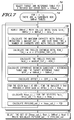
- the payload for channel transmissions without using any error correction or coding is first determined at step 302.
- the available payload for the channel using Trellis coding is determined.
- the available payload using Reed-Solomon coding is determined.
- the available payload for concatenated Reed-Solomon/Trellis coding is determined.
- the respective payloads for steps 302 - 308 are then compared and the coding configuration with the highest payload is then selected at step 310.
- a target signal-to-noise ratio (SNR) reference table for a desired bit error rate (BER) is selected, at step 402.
- SNRref(i) of the SNR reference table is then adjusted based on performance margin (PM) information, at step 404.
- Performance margin is the amount of extra margin required to account for changes in channel characteristics. For example, if the channel performance is known to vary within a 2 dB range over the time, using 2 dB of performance margin will allow the system to maintain the desired BER performance. As long as the channel conditions do not degrade more than the amount of system performance margin, performance is maintained.
- the maximum the channel capacity MAXCAP_UNC is determined using the adjusted SNR reference table and measured SNR values for the channel.
- One exemplary method for determining the capacity with such data is described in U.S. patent application number 08/937,759, entitled “Method and Apparatus for Configuring A Communication System,” filed September 25, 1997 by Levin, and in U.S. patent 5,852,633, entitled “Method for Allocating Data in a Data Communication System” issued December 22, 1998 to Levin et al. Another method of determining the capacity is described hereinafter with reference to FIG. 8.
- the presently discussed embodiment uses SNR reference tables which are updated with coding gains and performance margin, and the channel SNRs are compared to the SNR reference tables to generate capacity.
- Fine gain adjustments are used in the capacity calculation instead of computing fine gains as a post-allocation process.
- Fine gains are power adjustments in a limited range which can be used to equalize the SNR margin amongst carriers in a DMT system. For standard compliant ADSL, the range of power adjustment is +/- 2.5 dB. For example, if a carrier has a pre-fine gain SNR margin of 2 dB, and a fine gain of 1 dB, the resulting SNR margin is 3 dB.
- resulting capacities reflect full use of the communication bandwidth.
- An additional benefit is that the optimal fine gains adjustments are generated during the capacity calculation for the maximum capacity allocation. Previous capacity calculations computed maximum capacities without considering the effects of fine gain adjustments. The use of fine gain adjustments to calculate channel capacity is discussed hereinafter with reference to FIG. 8.
- a predetermined overhead value such as the framing value FOH for ADSL systems, is then subtracted from the capacity MAXCAP_UNC determined in step 406 to produce the uncoded payload PAYLOAD_UNC which is the user available capacity of the channel without coding.
- an illustrated method of determining payload for a channel using Trellis encoding is disclosed.
- the SNR reference table for the desired bit error rate (BER) is selected at step 502, and then adjusted for performance margin at step 504.
- the SNR reference table is then further adjusted with a Trellis gross coding gain GTREL at 506.
- each value SNRref(i) of the SNR reference table is adjusted by subtracting the Trellis gross gain GTREL.
- a Trellis gross gain look up table can be used.
- the Trellis gross gain can be based on the desired input or output bit error rate.
- An example of a Trellis gross gain table based on its input BER is as follows: BER 10-3 10-4 10-5 10-6 10-7 10-8 10-9 Gain dB 2.5 3 4 4.7 5 5.5 5.8
- a maximum Trellis capacity MAXCAP_TREL of the channel is calculated with the updated SNR reference table and the measured SNR values for the channel using a capacity calculation method.
- the number of frequency bins (BINS_TREL) that have capacity greater than zero bits is computed.
- the overhead for Trellis coding, labeled TOH (Trellis overhead bits), is determined by the formula shown in FIG. 5 at step 510.
- the Trellis overhead is equal to the number of bins used, divided by 2, rounded up, and then added to 4 as shown.
- the ceiling operation (CEIL) is a rounding up. For example, if the operand were at a value of 3.1 the ceiling would then be 4. Thus, the ceiling function takes any fractional amount up to the next highest integer value.
- the overhead such as framing overhead FOH and the Trellis overhead TOH are then subtracted from the Trellis capacity MAXCAP_TREL to produce a payload measurement PAYLOAD_TREL for the Trellis encoded system.
- Framing overhead is based on the structure of DMT data transmission and specified in the ADSL standard. The formula in step 512 provides that the payload for Trellis is equal to the maximum capacity using Trellis encoding minus the framing overhead and minus the Trellis overhead.
- the Reed Solomon (RS) coding configuration is based on three parameters: redundancy, R, payload data, K, and number of DMT data frames per RS codeword, S.
- the RS codeword is the total amount of DMT data for which R bytes of redundancy are used for error correction.
- the codeword size is variable and does not have to be the DMT frame size. For example, if the payload per DMT data frame is 10 bytes, S equals 1, and R equals 2 bytes, then 2 bytes of redundancy are used to correct 10 bytes of payload data.
- a target SNR reference table SNRref_t for the desired BER is selected, at step 602.
- An iterative loop is then entered for a set of candidate BERs, at 604.
- a candidate BER SNR reference table as shown at step 606.
- a capacity N_i of the channel is calculated based on the SNR reference table SNRref_i and the measured SNR values, at step 608.
- a difference is calculated between a particular ith candidate BER reference table SNRref_i and a target SNR reference table SNRref_t. This difference measurement is shown at step 610.
- the difference DIFF_i calculated in step 610 can be based on the same element in the two different tables or the average difference between respective elements.
- an SNR offset OFFSET_i is calculated by adding the difference determined in step 610 to a performance margin value PM that may optionally be provided from a user.
- a smallest redundancy value Rmin_i that provides a gross gain exceeding or equaling the offset is determined.
- One method of selecting the minimum R is to use a gross gain table which provides the gross gain for a capacity, N, based on R, the amount of redundancy.
- the example table listed below is in byte quantities. There can be a different table for each BER.
- the resulting payload PAYLOAD_i for the particular candidate BER is then determined by taking the payload K_i at such BER less the overhead FOH, as shown at step 618.
- the previous steps 608-618 are then repeated during an iterative loop for each of the sets of candidate BERs.
- the candidate BERs are dependent upon the particular application and system design, but typically vary between 10 -1 to 10 -10 .
- a maximum payload PAYLOAD_rs for all of the plurality of BER candidates is then determined, at step 620.
- the parameters corresponding to the selected maximum payload namely payload, redundancy, SNR reference, and capacity, is generated.
- the N_i values for each BER candidate could be multiplied by S, where S does not equal 1, to achieve a different codeword size, NS_i.
- S codeword size
- an exemplary value for N_i is 50.
- the corresponding NS_i is 100.
- the offset calculated during step 612 does not depend on S, and remains unchanged.
- the minimum redundancy RS_i which achieves the gross gain for NS_i can be obtained using the method in 614.
- KS_i NS_i ⁇ RS_i
- S can be fractional, 1, or greater than 1.
- a target SNR reference table for a desired BER is selected, at step 702.
- the loop at 704 processes a plurality of candidate error rates with corresponding BER SNR reference tables.
- the SNR reference table is adjusted with a Trellis gross coding gain (GTREL) at 706.
- the Trellis gross coding gains can be read from a table based on its input BER. (E.g., a Trellis gross gain table based on input BER such as that discussed above with reference to FIG. 5).
- a maximum capacity MAXCAP_CAT_i of the channel is calculated with the updated SNR reference table and the measured SNR values for the channel.
- the number of frequency bins of the channel with capacities greater than zero are recorded.
- the overhead for Trellis coding, labeled TOH is determined by the formula shown in FIG. 7 at step 710.
- the Trellis overhead is equal to the number of bins used, divided by 2, rounded up, and then added to 4 as shown.
- a difference is calculated between a particular ith candidate BER reference table and a target SNR reference table. This difference measurement is shown at step 714.
- an SNR offset is calculated by adding the difference determined in step 714 to a performance margin value that may optionally be provided from a user.
- a smallest redundancy value Rmin_i that provides a gross gain exceeding or equaling the offset is determined.
- a user payload, labeled Kmax_cat_i, for a selected redundancy, labeled Rmin_i is determined at step 720.
- the resulting payload for the particular candidate BER is then determined by taking the payload, Kmax_cat_i, at such BER less the overhead, as shown at step 722.
- the previous steps 706-722 are then repeated during the iterative loop for each of the sets of candidate BERs.
- a maximum payload for the concatenated coding technique is determined, at 724.
- the set of corresponding parameters for such concatenated encoding is also determined.
- the S parameter can be varied to provide a number of different RS configurations with different RS_min_i.
- the KS_cat_i for the selected RSmin_i in step 720 can be generated for each of the S settings, and the configuration with the maximum KSmax_cat_i can be selected.
- a method of estimating capacity of a multi-carrier communication channel using fine gain adjustments is illustrated.
- a signal-to-noise ratio (SNR) is estimated for each carrier i in the channel.
- the frequency bins with capacity less than a certain threshold are masked at step 804.
- An SNR reference table for the desired bit error rate is then selected at step 806.
- the selected SNR reference table is then updated based on coding gain (CG) and performance margin at step 808.
- Values for a maximum gain adjustment, MAXGAIN, a maximum number of bits per channel, NMAX, and an excess loop variable, EXCESS are initialized at step 810.
- a carrier capacity b i is then determined at step 812.
- a threshold to be compared with the excess loop variable is determined at step 814 and used in a loop comparison at step 816 in which the excess value is compared to the threshold. While the excess value exceeds the threshold, processing continues at 818 for bit allocation to various carriers.
- a carrier i is selected from a carrier pool. The carrier i is selected which has a minimum gatch and a particular carrier bit allocation b i which is less than the maximum number of bits per channel (NMAX). The gatch is the difference between the clipped current margin and clipped projected margin calculated in FIG. 9.
- the number of bits b i is incremented by B, at step 822, and the excess value is reduced by the applicable gatch for the selected carrier of the current iteration of loop 818 at step 824.
- B is an additional amount of bits based on bit allocation granularity and minimum bit allocation requirements. Typically, B is either 1 or 2.
- the currently selected carrier i is removed from the carrier pool at step 826.
- the fine gains fg(i) for the carrier is then set equal to the negative of the clipped performance margin for the carrier PM CL (i) step 828.
- the excess value is compared to the threshold at step 816. While the excess value exceeds the threshold, processing then continues again at step 818 and a new carrier is selected from the pool at step 820. Processing for the newly selected carrier proceeds in like manner as described above. When the excess value no longer exceeds the threshold at step 816, processing of the carriers is then completed at step 830.
- the fine gains can be reduced to meet the aggregate required power level. Additionally, if the total aggregate power is below the aggregate power limit, the fine gains can be increased to meet the aggregate power limit.
- the maximum capacity is calculated for each carrier by comparing the SNR for that carrier to the selected SNR reference table at step 902.
- Current margin clipped CM CL (i) is then calculated by taking the SNR for the particular carrier SNR(i) less the SNR reference value SNRref for the given capacity b i at step 904. If the capacity b i equals zero, then the clipped value for the particular carrier is set to zero at step 906. If the clipped value exceeds the maximum gain adjustment then the clipped value is set equal to the maximum gain adjustment at step 908.
- a projected clipped value for the carrier is set equal to the SNR of the carrier less the SNR reference value for the capacity b i incremented by 1 (or a larger bit granularity). If the projected margin clipped value for the carrier is less than the negative of the maximum gain adjustment, then the projected margin value for the carrier is set equal to zero at step 912. The excess value is then set equal to the excess value incremented by the calculated clipped value for the carrier at step 914. A gatch value for the particular carrier is set equal to the clipped value less the projected margin clipped value for the selected carrier at step 916. A fine gain value fg(i) is set equal to the negative of the clipped value for the particular carrier as shown at step 918. The prior calculations 904 to 918 are then repeated for each carrier of the channel.
- Figure 10 discloses a method for selecting a rate option from amongst the rate options received by transceiver 34 from the central office transceiver 42 at step 222 of FIG. 2.
- a rate option for a first selected rate option n, the redundancy per frame R f (n), the user payload K f (n), the framing overhead FOH, and the number of frames per Reed-Solomon (RS) code word S(n) are selected.
- the maximum capacity for a targeted bit error rate MAXCAP BERT can be calculated using trellis coding or no trellis coding as described in FIGs. 4 and 5.
- the corresponding gross trellis gain used to calculate MAXCAP BERT can be based on BER.
- the total data rate per frame N f (n) is determined to be the payload per frame K f (n) plus the redundancy per frame R f (n) + FOH.
- the total data rate per Reed Solomon code word N s (n) is determined to be the total data rate per frame K f (n) multiplied by the number of frames per Reed Solomon code word S(n).
- the redundancy per Reed Solomon code word R s (n) is also determined to be redundancy per frame R f (n) multiplied by the number of frames per Reed Solomon code word S(n).
- step 1040 it is determined whether the redundancy per Reed Solomon code word R s (n) equals zero. If the redundancy per RS code word R s (n) equals zero, control transitions to step 1042.
- step 1042 the total data rate per frame N f (n) is compared to the maximum capacity at the targeted bit error rate MAXCAP BERT . If the total data rate per frame N f (n) is less than or equal to the maximum capacity of the targeted error rate MAXCAP BERT , control transitions to step 1044 where the rate option currently being analyzed (e.g., the nth rate option) is selected for subsequent data transmission.
- the rate option currently being analyzed e.g., the nth rate option
- control transitions to step 1046 where the rate option being analyzed (e.g., the nth rate option) is not selected. Control then transitions to step 1010 and the process is repeated for the next rate option (e.g., the n+1 rate option).
- the rate option being analyzed e.g., the nth rate option
- the bit error rate for total data rate per frame of the current rate option (BER(n)) is determined. For example, the bit error rate corresponding to the calculated capacity which is closest to the current rate option is selected using the following table: BER 10-3 10-4 10-5 10-6 10-7 Max Capacity (bytes) 120 110 100 90 85
- the BER for Nf(n) can be determined using a comparison of the BER to the maximum capacity listed above.
- the above table can be populated by calculating the capacity of the communication channel based on the SNR reference table for each BER and the measured SNRs.
- the offset for the current rate option n is determined to be the targeted SNR reference value SNRref_t minus the SNR reference value SNR ref (n) for the bit error rate determined at step 1050 plus performance margin.
- the gross coding gain CG(n) for the current rate option is determined using the gross gain table for the bit error rate determined at step 1050.
- the gross current gain is compared to the offset. If the gross current gain is greater than the offset, control transitions to step 1082 where the current rate option is selected. If the gross coding gain is less than or equal to the offset control transitions to step 1084 where the current rate option is not selected. Control transitions from step 1084 to step 1010 to analyze the next rate option.
- a threshold can be defined so that decisions are not hard limited. For example in step 1042, if Nf(n) is 0.0001 greater than MAXCAP BERT , option n could still be selected if the threshold was set at 0.01.
- the illustrative methods described with reference to FIGs. 2-10 may be implemented in many ways.
- One particular implementation is to code such methods in computer software, such as assembly code that executes on a suitable digital signal processor, or other processing unit, embedded within a digital transceiver, such as ADSL transceivers 42 or 34.
- the software may be downloaded into computer readable form such as by burning the software into a read only memory that is coupled to the digital signal processor.
- the method steps described herein may be coded in a high level computer language, such as C language, and then loaded into a memory that is accessible to a processing device such as digital signal processor, microprocessor or other similar execution unit. Exemplary memories 43 and 35 are shown in Figure 1.
- the particular illustrative embodiments described herein have many benefits to a variable data rate communication system. For example, by intelligently selecting error correction methods and parameters on a per channel basis based on measured SNR and other channel characteristics, payload usable for data transmission may be greatly increased. Increased payload from the intelligent selective error correction methodology described in this application, can lead to improved transmission work data rates and thereby result in more data, video text, and voice, over a given channel and system. The result is higher over all bandwidth and usability of the communication system. Another advantage of improved coding and resulting payload performance increases, is that depending on the length of communication channel, such as twisted pair links having a length greater than 18000 feet or greater, systems not performing efficient coding matched to the channel may not be able to communicate data at all. Thus, the present illustrated embodiments may provide service to users otherwise unable to use a corresponding multicarrier communication system due to such system not being implemented based on the teachings herein.
- a method of processing data associated with a communication channel is provided.
- a first channel payload for the communication channel is determined using a first type of error correction (e.g., Trellis error correction).
- a second channel payload for the communication channel is determined using a second type of error correction (e.g., Reed-Solomon error correction).
- the first and second channel payloads are then compared.
- the communication channel may then be configured using one of the first and second types of error correction corresponding to a largest one of the first and second channel payloads.
- Additional channel payloads for the communication channel may be determined using a other types of error correction, including concatenated or combined error correction.
- the additional channel payloads are compared with each other and with the first and second channel payloads, whereafter the communication channel may be configured using the type of error correction corresponding to the largest one of the all of the channel payloads.
- a channel payload may be determined using no error correction.
- the no error correction payload may also be compared to the other payloads to determine whether error correction should be enabled at all. For example, no error correction should be used where the no error correction payload is larger than the other payloads.
- a method for communicating over a digital communication channel is provided.
- a message is communicated over the digital communication channel.
- the message includes a first indicator identifying whether error correction is enabled.
- the indicator is determined based upon channel characteristics.
- the channel characteristics may include, for example, a gross error correction gain which is independent of error correction overhead.
- a first channel payload may be determined for the communication channel using the error correction.
- a second channel payload may be determined for the communication channel using no error correction. The first and second channel payloads may then be compared.
- the first indicator may then indicate that error correction is enabled when the first channel payload is larger than the second channel payload, and that error correction is disabled when the second channel payload is larger than the first channel payload.
- the message may include a second indicator to identify whether error correction is available.
- the first indicator may identify whether the error correction is disabled even if the error correction is available. After comparing the first and second channel payloads, the first indicator may be asserted to indicate that the error correction is available, and the second indicator is asserted when the second channel payload is larger than the first channel payload and deasserted when the first channel payload is larger than the second channel payload.
- the error correction may be Trellis coding, Reed-Solomon coding, or both Trellis coding and Reed-Solomon coding, for example.
- a method of communicating over a digital communication channel is provided.
- the digital communication channel is activated so that data may be communicated over the data communication channel.
- Any error correction present over the digital communication channel is disabled based upon channel characteristics (e.g., when a measured channel payload using no error correction is larger than a measured channel payload using error correction). Data communication may therefore be enhanced over such a digital communication channel while the error correction is disabled.
- a method of configuring a communication system using gross gain is provided.
- An uncoded payload is determined.
- At least one coded payload is determined using at least one of a plurality of codes.
- One of the uncoded payload and the at least one coded payload is determined to have the greatest payload.
- the communication system is configured to use a code corresponding to the greatest payload if the greatest payload is a coded payload, and the communication system is configured without using a code if the uncoded payload is the greatest payload.
- a method of calculating payload based upon channel characteristics of a data communication channel is provided.
- Channel SNRs of the data communication channel are measured.
- a target SNR reference table is selected for a target bit error rate.
- the target SNR reference table is adjusted by applying at least one of a gross coding gain and a performance margin.
- a payload is determined by calculating a channel capacity based on the measured channel SNRs and the target SNR reference table. More than one payload may be determined. For example, a first coded payload may be determined using a first code, a second coded payload may be determined using a second code, and a concatenated payload may be determined using the first and second codes.
- the payload may be an uncoded payload or a coded payload.
- the channel capacity may be adjusted based on predetermined overhead or coding overhead, which may be zero.
- a method of initializing a digital communication channel includes activating the channel, determining channel characteristics for the channel, and selecting an error correction configuration from among a plurality of error correction configurations based on the channel characteristics.
- the channel characteristics may include, for example, signal-to-noise ratios.
- a method of determining a payload for a block coded error correction configuration (e.g., a Reed-Solomon error correction configuration) is provided.
- One or more of the following operations is performed: (1.) a capacity of a digital communication channel is calculated based upon reference signal-to-noise ratio values and based upon measured signal-to-noise ratio values; (2.) a difference between reference signal-to-noise ratio values and target reference signal-to-noise ratio values is calculated; and (3.) a redundancy value is determined which provides a coding gain that exceeds a difference between reference signal-to-noise ratio values and target reference signal-to-noise ratio values.
- the payload of the digital communication channel is then determined.
- an apparatus in another embodiment, includes a data processing unit, at least one computer readable medium and a plurality of software modules.
- the at least one computer readable medium is coupled to the data processing unit.
- a first software module is encoded on the at least one computer readable medium to be executable by the data processing unit to activate a digital communication channel.
- a second software module is encoded on the at least one computer readable medium to be executable by the data processing unit to determine channel characteristics for the digital communication channel.
- a third software module is encoded on the at least one computer readable medium to be executable by the data processing unit to select one of a plurality of error correction configurations based on the channel characteristics.
- the first, second and third software modules may be incorporated into the same or another software module.
- Each of the first, second and third software modules may consist of one or more computer program instructions.
- system 30 uses Asymmetric Digital Subscriber Line (ADSL), other types of digital subscriber line technologies may be used.
- ADSL Asymmetric Digital Subscriber Line
- a few of the many other exemplary digital subscriber line technologies include the following: ADSL Lite, DSL Lite, G.Lite, IDSL (ISDN DSL), SDSL, splitterless ADSL, UDSL (Unidirectional DSL), x2/DSL, and any presently available or future variants thereof.
- the above listed variants of digital subscriber line technology are often collectively referred to as xDSL. Each technology offers different speeds, ranges, and operating characteristics.
- splitter 44 and ADSL transceiver 42 may be merged into an ADSL modem unit coupled to a memory.
- alternate embodiments of system 30 may include more, fewer, or different blocks.
- alternate embodiments of system 30 may or may not have some of or different types of peripheral devices 50-56. Some embodiments may combine multiple instances of a particular component.
- transceiver 42 may be, include or placed within any type of processing unit including but not limited to a microprocessor (e.g., a processing unit fabricated on a single integrated circuit chip), a microcontroller (e.g., a microprocessor including memory and/or I/O devices integrated therein), a multi-chip module processing unit, a computer system board, an embedded computer system and/or a general purpose computer system.
- a microprocessor e.g., a processing unit fabricated on a single integrated circuit chip
- microcontroller e.g., a microprocessor including memory and/or I/O devices integrated therein
- multi-chip module processing unit e.g., a computer system board, an embedded computer system and/or a general purpose computer system.
- blocks of circuitry may include or be replaced by modules of software, or general purpose circuitry for execution of modules of software, or software for simulating such blocks of circuitry.
- Some or all of the blocks of FIGs. 2 - 10 may be executed by, and therefore represent, instructions or a module (e.g., a software module) or a portion of a module and/or a computer system user.
- a module e.g., a software module
- the operations thereof and any modules therefor may be executed on a computer system configured to execute the operations of the method and/or may be executed from machine-readable and/or computer-readable media.
- the method may be embodied in a computer-readable medium for configuring a computer system to execute the method.
- the software modules may be stored within and/or transmitted to a computer system memory to configure the computer system to perform the functions of the module.
- Computer readable media may be permanently, removably or remotely coupled to transceiver 42.
- Computer readable media may non-exclusively include, for example, any number of the following: magnetic storage media including disk and tape storage media; optical storage media such as compact disk media (e.g., CD-ROM, CD-R, etc.) and digital video disk storage media; nonvolatile memory/storage including semiconductor-based memory units such as FLASH memory, EEPROM, EPROM, ROM; ferromagnetic memory units; volatile storage media including registers, buffers or caches, main memory, RAM, etc.; application specific integrated circuitry; and data transmission media including computer network, point-to-point telecommunication, and carrier wave transmission media.
- the software modules or portions thereof may be embodied in a file which may be a device, a terminal, a local or remote file, a socket, a network connection, a signal, or other expedient of communication or state change.
- a file which may be a device, a terminal, a local or remote file, a socket, a network connection, a signal, or other expedient of communication or state change.
- Other new and various types of computer-readable media may be used to store and/or transmit software modules including the operations and decisions discussed herein.
- ADSL remote terminal 32 is a computer system or is a card in a computer system such as a personal computer system.
- Other embodiments may include different types of computer systems.
- Computer systems are information handling systems which can be designed to give independent computing power to one user or a plurality of users. Computer systems may be found in many forms including but not limited to mainframes, minicomputers, workstations, servers, personal computers, notepads and embedded systems.
- a typical computer system includes at least one processing unit, associated memory and a number of input/output (I/O) devices.
- Exemplary I/O devices include display monitors, keyboards, diskette drives, fixed disk storage devices, printers, modems (e.g., an ADSL modem including ADSL transceiver 42 and splitter 44), sound and video devices or specialized communication devices, computer readable media such as floppy or hard disk drives and CD-ROM drives. Many such computer systems use a system board to electrically connect these components together.
- a computer system processes information according to a program and produces resultant output information via the I/O devices.
- a program is a list of internally stored instructions such as a particular application program and/or an operating system.
- a software module may include a program. The programs that control the operation of a computer system are commonly referred to as software applications or simply software.
- the claim reads on the apparatus or method regardless of whether the apparatus or method includes another such similar feature.
- This use of the word "a” as a nonlimiting, introductory article to a feature of a claim is adopted herein by Applicants as being identical to the accepted interpretation adopted by many courts in the past, notwithstanding any anomalous or precedential case law to the contrary that may be found.
- a claim element is described in the claims below as including or comprising an aforementioned feature (e.g., "the” feature), it is intended that that element not be limited to one and only one of the feature described.
Landscapes
- Engineering & Computer Science (AREA)
- Signal Processing (AREA)
- Computer Networks & Wireless Communication (AREA)
- Quality & Reliability (AREA)
- Power Engineering (AREA)
- Detection And Prevention Of Errors In Transmission (AREA)
- Error Detection And Correction (AREA)
Priority Applications (1)
| Application Number | Priority Date | Filing Date | Title |
|---|---|---|---|
| EP06118723A EP1715611A1 (fr) | 1999-10-19 | 2000-09-29 | Méthode et système d'identification d'une configuration améliorée pour un système de communication avec gain de codage |
Applications Claiming Priority (2)
| Application Number | Priority Date | Filing Date | Title |
|---|---|---|---|
| US09/420,471 US6625777B1 (en) | 1999-10-19 | 1999-10-19 | Method of identifying an improved configuration for a communication system using coding gain and an apparatus therefor |
| EP00121153A EP1094629A3 (fr) | 1999-10-19 | 2000-09-29 | Méthode et système d'identification d'une configuration améliorée pour un système de communication avec gain de codage |
Related Parent Applications (1)
| Application Number | Title | Priority Date | Filing Date |
|---|---|---|---|
| EP00121153A Division EP1094629A3 (fr) | 1999-10-19 | 2000-09-29 | Méthode et système d'identification d'une configuration améliorée pour un système de communication avec gain de codage |
Related Child Applications (1)
| Application Number | Title | Priority Date | Filing Date |
|---|---|---|---|
| EP06118723A Division EP1715611A1 (fr) | 1999-10-19 | 2000-09-29 | Méthode et système d'identification d'une configuration améliorée pour un système de communication avec gain de codage |
Publications (2)
| Publication Number | Publication Date |
|---|---|
| EP1655873A2 true EP1655873A2 (fr) | 2006-05-10 |
| EP1655873A3 EP1655873A3 (fr) | 2006-08-30 |
Family
ID=23666619
Family Applications (3)
| Application Number | Title | Priority Date | Filing Date |
|---|---|---|---|
| EP06101254A Withdrawn EP1655873A3 (fr) | 1999-10-19 | 2000-09-29 | Méthode et système d'identification d'une configuration améliorée pour un système de communication avec gain de codage |
| EP06118723A Ceased EP1715611A1 (fr) | 1999-10-19 | 2000-09-29 | Méthode et système d'identification d'une configuration améliorée pour un système de communication avec gain de codage |
| EP00121153A Withdrawn EP1094629A3 (fr) | 1999-10-19 | 2000-09-29 | Méthode et système d'identification d'une configuration améliorée pour un système de communication avec gain de codage |
Family Applications After (2)
| Application Number | Title | Priority Date | Filing Date |
|---|---|---|---|
| EP06118723A Ceased EP1715611A1 (fr) | 1999-10-19 | 2000-09-29 | Méthode et système d'identification d'une configuration améliorée pour un système de communication avec gain de codage |
| EP00121153A Withdrawn EP1094629A3 (fr) | 1999-10-19 | 2000-09-29 | Méthode et système d'identification d'une configuration améliorée pour un système de communication avec gain de codage |
Country Status (2)
| Country | Link |
|---|---|
| US (1) | US6625777B1 (fr) |
| EP (3) | EP1655873A3 (fr) |
Cited By (1)
| Publication number | Priority date | Publication date | Assignee | Title |
|---|---|---|---|---|
| WO2010033704A3 (fr) * | 2008-09-17 | 2010-11-04 | Qualcomm Incorporated | Optimisation du débit dans un système de communication sans fil |
Families Citing this family (36)
| Publication number | Priority date | Publication date | Assignee | Title |
|---|---|---|---|---|
| US6544379B2 (en) * | 1993-09-16 | 2003-04-08 | Hitachi, Ltd. | Method of holding substrate and substrate holding system |
| US6782096B1 (en) * | 1998-11-12 | 2004-08-24 | Paradyne Corporation | Subscriber line driver and termination |
| US6975694B1 (en) * | 1999-12-15 | 2005-12-13 | Paradyne Corporation | Digital subscriber line driver |
| US6654384B1 (en) * | 1999-12-30 | 2003-11-25 | Aperto Networks, Inc. | Integrated self-optimizing multi-parameter and multi-variable point to multipoint communication system |
| US7366133B1 (en) | 1999-12-30 | 2008-04-29 | Aperto Networks, Inc. | Integrated, self-optimizing, multi-parameter/multi-variable point-to-multipoint communication system [II] |
| US6886181B1 (en) * | 2000-07-07 | 2005-04-26 | Critical Telecom Corp. | Extended distribution of ADSL signals |
| US6636488B1 (en) | 2000-10-11 | 2003-10-21 | Aperto Networks, Inc. | Automatic retransmission and error recovery for packet oriented point-to-multipoint communication |
| US7110467B2 (en) * | 2000-10-12 | 2006-09-19 | 3Com Corporation | Performance evaluation of a G.dmt-compliant digital subscriber line system |
| US7103096B2 (en) * | 2000-10-12 | 2006-09-05 | 3Com Corporation | Performance evaluation of multicarrier channels with forward error correction and automatic retransmission request |
| US7000011B1 (en) * | 2000-11-06 | 2006-02-14 | Hewlett-Packard Development Company, Lp. | Designing interconnect fabrics |
| US7031345B1 (en) * | 2000-12-21 | 2006-04-18 | Cisco Technology, Inc. | Method and system for rate adaptive ISDN communication |
| KR101358583B1 (ko) | 2001-05-14 | 2014-02-04 | 인터디지탈 테크날러지 코포레이션 | 다운링크 자원 할당을 위한 채널 품질 측정값 제공 방법, 무선 디지털 통신 시스템 및 사용자 장치 |
| US6718493B1 (en) | 2001-05-17 | 2004-04-06 | 3Com Corporation | Method and apparatus for selection of ARQ parameters and estimation of improved communications |
| US7164649B2 (en) * | 2001-11-02 | 2007-01-16 | Qualcomm, Incorporated | Adaptive rate control for OFDM communication system |
| WO2003061179A1 (fr) * | 2001-12-28 | 2003-07-24 | Koninklijke Philips Electronics N.V. | Protection inegale contre les erreurs par correction d'erreurs sans voie de retour sur la base de codes de reed-solomon |
| US20030145294A1 (en) | 2002-01-25 | 2003-07-31 | Ward Julie Ann | Verifying interconnect fabric designs |
| US9009004B2 (en) * | 2002-01-31 | 2015-04-14 | Hewlett-Packasrd Development Comany, L.P. | Generating interconnect fabric requirements |
| US7197276B2 (en) * | 2002-03-15 | 2007-03-27 | Broadcom Corporation | Downstream adaptive modulation in broadband communications systems |
| US20030189950A1 (en) * | 2002-04-08 | 2003-10-09 | Stephen Spear | Optimization of a wireless interface based on communication type |
| FR2840477B1 (fr) * | 2002-06-03 | 2005-02-04 | Nortel Networks Ltd | Procede d'adaptation de liens radio et unite de controle mettant en oeuvre le procede |
| US20040213225A1 (en) * | 2003-04-28 | 2004-10-28 | Texas Instruments Incorporated | Re-use of channel estimation information in a wireless local area network |
| US20040240464A1 (en) * | 2003-05-30 | 2004-12-02 | Fite Wayne Charles | Method of transmitting data to reduce bit errors in communication systems |
| US7068755B2 (en) * | 2003-08-20 | 2006-06-27 | Intel Corporation | Methods and apparatus for characterizing subscriber loop based on analysis of DSL handshaking signals and for optimization of DSL operation |
| EP1528702B1 (fr) * | 2003-11-03 | 2008-01-23 | Broadcom Corporation | Décodage de code de correction d'erreurs en avant (FEC) avec paramètres dynamiques |
| US20050265359A1 (en) * | 2004-05-13 | 2005-12-01 | Drew Julie W | Optimizing switch port assignments |
| US7072129B1 (en) * | 2004-06-30 | 2006-07-04 | Western Digital Technologies, Inc. | Identifying defective data sectors in a disk drive |
| KR101025072B1 (ko) * | 2004-12-30 | 2011-03-25 | 엘지에릭슨 주식회사 | 에이치에이알큐 방식을 사용하는 통신 시스템에서 최적의리던던시 버전 선택 방법 |
| US20070180349A1 (en) * | 2006-01-31 | 2007-08-02 | Jacobsen Eric A | Techniques for uequal error protection for layered protection applications |
| JP4732193B2 (ja) * | 2006-03-01 | 2011-07-27 | 住友電工ネットワークス株式会社 | 通信装置、通信システムおよび通信方法 |
| US8671331B2 (en) * | 2006-08-25 | 2014-03-11 | Tellabs Operations, Inc. | Apparatus and method for communicating FEC mode and alarming mismatch |
| US7836380B2 (en) * | 2006-10-31 | 2010-11-16 | Intel Corporation | Destination indication to aid in posted write buffer loading |
| WO2008108008A1 (fr) * | 2007-03-07 | 2008-09-12 | Sumitomo Electric Networks, Inc. | Système d'adaptation de liaison et procédé pour systèmes de transmission à porteuses multiples |
| US8675513B1 (en) | 2010-06-30 | 2014-03-18 | Sprint Spectrum L.P. | Method and system for using multi-channel communication links |
| DE102013220374A1 (de) * | 2013-10-09 | 2015-04-09 | Robert Bosch Gmbh | Teilnehmerstation für ein Bussystem und Verfahren zur breitbandigen CAN-Kommunikation |
| US10116336B2 (en) * | 2014-06-13 | 2018-10-30 | Sandisk Technologies Llc | Error correcting code adjustment for a data storage device |
| US10893562B1 (en) * | 2019-03-18 | 2021-01-12 | Sprint Spectrum L.P. | Dynamic sharing of secondary carrier among multiple primary carriers in dual-connectivity service |
Family Cites Families (12)
| Publication number | Priority date | Publication date | Assignee | Title |
|---|---|---|---|---|
| JP3282180B2 (ja) * | 1990-08-28 | 2002-05-13 | ソニー株式会社 | 磁気記録再生装置 |
| US5600663A (en) * | 1994-11-16 | 1997-02-04 | Lucent Technologies Inc. | Adaptive forward error correction system |
| US5546411A (en) * | 1995-02-28 | 1996-08-13 | Motorola, Inc. | Method and apparatus for adaptively selecting a communication strategy in a selective call radio communication system |
| US5699369A (en) * | 1995-03-29 | 1997-12-16 | Network Systems Corporation | Adaptive forward error correction system and method |
| GB2306867B (en) * | 1995-10-26 | 1998-06-03 | Bosch Gmbh Robert | Method of optimizing the transmission of signals |
| US5828677A (en) * | 1996-03-20 | 1998-10-27 | Lucent Technologies Inc. | Adaptive hybrid ARQ coding schemes for slow fading channels in mobile radio systems |
| US5699365A (en) | 1996-03-27 | 1997-12-16 | Motorola, Inc. | Apparatus and method for adaptive forward error correction in data communications |
| US5852633A (en) | 1996-06-07 | 1998-12-22 | Motorola, Inc. | Method for allocating data in a data communication system |
| US6044485A (en) * | 1997-01-03 | 2000-03-28 | Ericsson Inc. | Transmitter method and transmission system using adaptive coding based on channel characteristics |
| US6130882A (en) | 1997-09-25 | 2000-10-10 | Motorola, Inc. | Method and apparatus for configuring a communication system |
| US6370669B1 (en) * | 1998-01-23 | 2002-04-09 | Hughes Electronics Corporation | Sets of rate-compatible universal turbo codes nearly optimized over various rates and interleaver sizes |
| US6182264B1 (en) * | 1998-05-22 | 2001-01-30 | Vlsi Technology, Inc. | Smart dynamic selection of error correction methods for DECT based data services |
-
1999
- 1999-10-19 US US09/420,471 patent/US6625777B1/en not_active Expired - Lifetime
-
2000
- 2000-09-29 EP EP06101254A patent/EP1655873A3/fr not_active Withdrawn
- 2000-09-29 EP EP06118723A patent/EP1715611A1/fr not_active Ceased
- 2000-09-29 EP EP00121153A patent/EP1094629A3/fr not_active Withdrawn
Cited By (2)
| Publication number | Priority date | Publication date | Assignee | Title |
|---|---|---|---|---|
| WO2010033704A3 (fr) * | 2008-09-17 | 2010-11-04 | Qualcomm Incorporated | Optimisation du débit dans un système de communication sans fil |
| US8848549B2 (en) | 2008-09-17 | 2014-09-30 | Qualcomm Incorporated | Optimizing throughput in a wireless communication system |
Also Published As
| Publication number | Publication date |
|---|---|
| EP1715611A1 (fr) | 2006-10-25 |
| EP1094629A2 (fr) | 2001-04-25 |
| EP1655873A3 (fr) | 2006-08-30 |
| EP1094629A3 (fr) | 2004-01-28 |
| US6625777B1 (en) | 2003-09-23 |
Similar Documents
| Publication | Publication Date | Title |
|---|---|---|
| US6625777B1 (en) | Method of identifying an improved configuration for a communication system using coding gain and an apparatus therefor | |
| US11543979B2 (en) | Resource sharing in a telecommunications environment | |
| US6801570B2 (en) | Intelligent rate option determination method applied to ADSL transceiver | |
| EP1275229B1 (fr) | Systemes et procedes destines a un systeme de modulation a porteuses multiples presentant une marge variable | |
| Grunheid et al. | A blockwise loading algorithm for the adaptive modulation technique in OFDM systems | |
| EP1296494B1 (fr) | Allocation de puissance de canaux dans un système de transmission de données avec fréquences multiples | |
| US6775320B1 (en) | Method and a multi-carrier transceiver supporting dynamic switching between active application sets | |
| US7965649B2 (en) | Apparatus and method for feedback of subcarrier quality estimation in an OFDM/OFDMA system | |
| US6480475B1 (en) | Method and system for accomodating a wide range of user data rates in a multicarrier data transmission system | |
| EP1538802A2 (fr) | Dispositif et procédé de contrôle de l'adaptation de la modulation et du codage dans un système de communication de multiplexage par répartition en fréquences orthogonales | |
| JP5044017B2 (ja) | 通信システムにおけるチャネル品質情報の通信のための方法および装置 | |
| EP2216924A1 (fr) | Système de radio communication, dispositif d'émission radio, procédé de radio communication et programme | |
| CN1961513B (zh) | 多载波通信环境中语音业务的自适应调度 | |
| EP3306847A2 (fr) | Appareil de communication, système de communication et méthode de communication | |
| US20070071120A1 (en) | Peak to average power reduction using channel state information | |
| KR20050100528A (ko) | 직교 주파수 분할 다중 접속 방식을 사용하는 통신시스템에서 전력 제어 장치 및 방법 | |
| CN101300768A (zh) | 用于在无线通信系统中对数据字进行自适应编码、调制和传输的方法及传输单元 | |
| JP4308009B2 (ja) | Ofdmシステム用のレート選択 | |
| EP2056552A1 (fr) | Système multi-porteur avec commutation dynamique entre des ensembles d'applications actifs | |
| US6732281B1 (en) | System and method for loading data onto carriers | |
| US20070110176A1 (en) | Systems and Methods for Improved Bit-Loading for Discrete Multi-Tone Modulated Multiple Latency Applications | |
| CN101057474B (zh) | 在正交频分多址无线通信系统中处理数字信号的装置和方法 | |
| CN101151807B (zh) | 通过相位调制复用来利用多用户分集 | |
| WO2007027977A2 (fr) | Systemes et procedes de resolution de la difference des marges du rapport signal sur bruit dans des systemes xdsl a multitonalite discrete et double delai de transit dans des conditions de bruit colore | |
| CN102007743B (zh) | 用信道频带发送/接收通信信号的频带高效方法和系统 |
Legal Events
| Date | Code | Title | Description |
|---|---|---|---|
| PUAI | Public reference made under article 153(3) epc to a published international application that has entered the european phase |
Free format text: ORIGINAL CODE: 0009012 |
|
| AC | Divisional application: reference to earlier application |
Ref document number: 1094629 Country of ref document: EP Kind code of ref document: P |
|
| AK | Designated contracting states |
Kind code of ref document: A2 Designated state(s): AT BE BG CH CY CZ DE DK EE ES FI FR GB GR HU IE IS IT LI LT LU LV MC NL PL PT RO SE SI SK TR |
|
| AX | Request for extension of the european patent |
Extension state: AL BA HR MK YU |
|
| PUAL | Search report despatched |
Free format text: ORIGINAL CODE: 0009013 |
|
| AK | Designated contracting states |
Kind code of ref document: A3 Designated state(s): AT BE BG CH CY CZ DE DK EE ES FI FR GB GR HU IE IS IT LI LT LU LV MC NL PL PT RO SE SI SK TR |
|
| AX | Request for extension of the european patent |
Extension state: AL BA HR MK YU |
|
| RIC1 | Information provided on ipc code assigned before grant |
Ipc: H04L 5/14 20060101ALI20060725BHEP Ipc: H04L 27/26 20060101ALI20060725BHEP Ipc: H04L 1/00 20060101AFI20060316BHEP |
|
| RIN1 | Information on inventor provided before grant (corrected) |
Inventor name: DJORDJEVIC, JAKSA Inventor name: KOSMACH, JAMES J. Inventor name: LEVIN, HOWARD EARL |
|
| 17P | Request for examination filed |
Effective date: 20070228 |
|
| AKX | Designation fees paid |
Designated state(s): DE FR GB IT NL |
|
| 17Q | First examination report despatched |
Effective date: 20070417 |
|
| STAA | Information on the status of an ep patent application or granted ep patent |
Free format text: STATUS: THE APPLICATION IS DEEMED TO BE WITHDRAWN |
|
| 18D | Application deemed to be withdrawn |
Effective date: 20070828 |