EP1656494B1 - Valve-operating lever - Google Patents
Valve-operating lever Download PDFInfo
- Publication number
- EP1656494B1 EP1656494B1 EP04756911A EP04756911A EP1656494B1 EP 1656494 B1 EP1656494 B1 EP 1656494B1 EP 04756911 A EP04756911 A EP 04756911A EP 04756911 A EP04756911 A EP 04756911A EP 1656494 B1 EP1656494 B1 EP 1656494B1
- Authority
- EP
- European Patent Office
- Prior art keywords
- valve
- connector member
- arm
- aperture
- follower
- Prior art date
- Legal status (The legal status is an assumption and is not a legal conclusion. Google has not performed a legal analysis and makes no representation as to the accuracy of the status listed.)
- Expired - Lifetime
Links
- 239000002184 metal Substances 0.000 claims description 3
- 230000004323 axial length Effects 0.000 claims 2
- 238000000034 method Methods 0.000 description 21
- 238000010276 construction Methods 0.000 description 17
- 238000002485 combustion reaction Methods 0.000 description 3
- 239000000463 material Substances 0.000 description 3
- 239000012530 fluid Substances 0.000 description 2
- 239000000446 fuel Substances 0.000 description 2
- 239000007789 gas Substances 0.000 description 2
- 238000004519 manufacturing process Methods 0.000 description 2
- 239000007787 solid Substances 0.000 description 2
- 238000007373 indentation Methods 0.000 description 1
- 230000001788 irregular Effects 0.000 description 1
- 238000005480 shot peening Methods 0.000 description 1
- 238000005482 strain hardening Methods 0.000 description 1
Images


Classifications
-
- F—MECHANICAL ENGINEERING; LIGHTING; HEATING; WEAPONS; BLASTING
- F01—MACHINES OR ENGINES IN GENERAL; ENGINE PLANTS IN GENERAL; STEAM ENGINES
- F01L—CYCLICALLY OPERATING VALVES FOR MACHINES OR ENGINES
- F01L1/00—Valve-gear or valve arrangements, e.g. lift-valve gear
- F01L1/12—Transmitting gear between valve drive and valve
- F01L1/18—Rocking arms or levers
-
- F—MECHANICAL ENGINEERING; LIGHTING; HEATING; WEAPONS; BLASTING
- F01—MACHINES OR ENGINES IN GENERAL; ENGINE PLANTS IN GENERAL; STEAM ENGINES
- F01L—CYCLICALLY OPERATING VALVES FOR MACHINES OR ENGINES
- F01L2303/00—Manufacturing of components used in valve arrangements
Definitions
- the present invention relates generally to internal combustion engines. More particularly, the present invention relates to a direct lever for controlling valve opening and closing.
- Internal combustion engines include valves that are operated at precise intervals to allow fuel and air to enter a cylinder or to allow exhaust gas to escape.
- a cam shaft driven by the engine actuates the valves to control the timing.
- valve-actuating levers that actuate push rods to open and close valves.
- the actuating levers include one arm that rides on a cam and a second arm that actuates the push rod.
- One such valve-actuating lever is disclosed in U.S. Patent No. 6,349,688 to Gracyalny .
- the valve-actuating lever of Gracyalny is costly to manufacture and requires precise techniques to maintain the necessary tolerances.
- the present invention provides a valve-operating lever comprising a valve arm including a first aperture defining a valve arm engagement portion.
- the lever also includes a connector member having an outside surface and a first stop. The connector member and the first stop cooperate to define a first engagement portion. A first portion of the connector member overlays a portion of the valve arm adjacent the first aperture, and the valve arm engagement portion engages the first engagement portion.
- the invention provides a direct lever system for an engine.
- the system including a cylinder bore having an outer end.
- the system also includes a cam assembly having at least one cam surface and an axis inward of the outer end of the cylinder bore, two valves having opened and closed positions, and two valve stems. Each valve stem is attached to one of the two valves.
- a cylinder head substantially encloses the outer end, with the valves being seated in the cylinder head.
- the system further includes two pivotably mounted valve-operating levers. At least one of the valve-operating levers includes a connector member having a lever arm end and a valve arm end. The connector member defines a pivot axis about which the valve-operating lever pivots.
- the valve-operating lever also includes a lever arm having an aperture. A portion of the connector member overlays at least a portion of the lever arm adjacent the aperture to fixedly attach the lever arm to the connector member.
- the lever arm has a cam follower surface in contact with the at least one cam surface, and a valve arm including an aperture. A portion of the connector member overlays at least a portion of the valve arm adjacent the aperture to fixedly attach the valve arm to the connector member.
- the invention provides a method of manufacturing a valve-operating lever that includes a connector member having an outside diameter.
- the method includes providing a valve arm having a first aperture, and forming a first stop at a first end of the connector member.
- the method also includes positioning the valve arm adjacent the first stop such that at least part of the connector member is positioned within the first aperture, and deforming the first end of the connector member to fixedly attach the valve arm to the connector member.
- the present invention provides a method of assembling a valve-operating lever, the valve-operating lever including a valve arm having a first aperture, a lever arm having a second aperture, and a connector member.
- the method includes positioning the valve arm on a first end of the connector member such that a portion of the connector member extends at least partially through the first aperture.
- the method also includes roller burnishing the first end of the connector member to deform the first end of the connector member, and fixedly attach the valve arm to the connector member.
- the method further includes positioning the lever arm on a second end of the connector member such that a portion of the connector member extends at least partially through the second aperture.
- the method also includes roller burnishing the second end of the connector member to deform the second end of the connector member and fixedly attach the lever arm to the connector member.
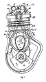
- FIG. 1 an internal combustion engine 10 including two valve-operating levers 15 of the present invention is illustrated.
- the engine 10 is similar to the engine disclosed, in U.S. Patent No. 6,349,688 the contents of which are incorporated herein by reference.
- the engine 10 of Fig. 1 includes a cylinder 20 having a bore in which a piston reciprocates.
- the cylinder bore has an outer end adjacent a cylinder head 25 and the top dead center (TDC) position of the piston.
- the engine 10 also includes a cam assembly 30 that has one or more cam surfaces 35.
- the cam assembly 30 rotates about an axis 1-1 that is positioned inward, or as in Fig. 1 , beneath and in front of the outer end of the cylinder bore.
- two valves move between open and closed positions to admit fuel and air and to discharge exhaust gases.
- each valve-operating lever 15 includes a follower portion 40 that rides on the cam surface 35 and a valve-actuating portion 45 that moves a push rod 50 to actuate the valve.
- Each valve includes its own valve-actuating lever 15 thus allowing for individual control of the valves.
- a biasing member such as a torsional spring 52, biases the lever 15 to assure that the follower portion 40 remains in contact with the cam surface 35 at operating speeds.
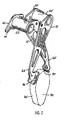
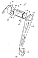
- the valve-operating lever 15 includes a connector member 55, a valve arm 60, and a follower arm 65.
- the connector member 55 is preferably a generally hollow tubular member having a first end 70 and a second end 75.
- the first end 70 includes a first reduced-diameter portion 80
- the second end 75 includes a second reduced-diameter portion 85.
- the first reduced-diameter portion 80 defines a first stop in the form of a first shoulder 90
- the second reduced-diameter portion defines a second stop in the form of a second shoulder 92.
- the reduced-diameter portions 80, 85 provide attachment points for the valve arm 60 and the follower arm 65.
- the stops take forms other then shoulders 90 defined by reduced-diameter portions 80, 85.
- one construction uses a ridge positioned along the length of a substantially constant diameter connector member. In this construction, no reduced diameter portion or shoulder is necessary.
- small intermittent upsets of the connector member material cooperate to function as stops.
- the connector member 55 includes lances that extend slightly above the surface of the connector member 55. The lances limit axial movement of the arms 60, 65 along the connector member 55.
- the stops can take many forms. As such, the invention should not be limited to the few examples described herein. Any component or feature that acts to inhibit the free movement of the arms 60, 65 along the length of the connector member 55 can be considered a stop.
- the wall thickness of the connector member 55 along with the diameter are chosen to assure adequate torsional stiffness during operation, while still providing the necessary machinability to complete the assembly.
- a thick wall will result in good stiffness, the wall may be too thick to deform during the assembly process.
- a thin wall can result in inadequate stiffness, which may cause inaccurate movement, incomplete valve actuation, or early failure of the connector member 55.
- many different wall diameters and wall thicknesses are envisioned.
- a solid cylinder is used. The ends of the solid cylinder are bored out to provide regions that are connectable to the valve arm 60 and the follower arm 65.
- the wall thickness is thin enough to facilitate attachment of the valve arm 60 and the follower arm 65 without providing a reduced-diameter portion 80, 85.
- the arms attach directly to the outer surface of the connector member and a stop other than a reduced diameter portion is employed (e.g., lances).
- the first reduced-diameter portion 80 of the connector member 55 is better illustrated.
- the first reduced-diameter portion 80 defines the first shoulder 90 adjacent the large diameter of the connector member 55.
- the first reduced-diameter portion 80 of Fig. 4 includes a knurled surface 95.
- the knurls 95 provide a rough or uneven surface that improves the connection between the connector member 55 and the arms 60, 65. While the term “knurl” is commonly used to describe a specific surface texture that enhances one's grip on an object, as used herein the term “knurl” should be read broadly.
- knurl should be read to include surface features such as, but not limited to knurling, axial grooves, radial grooves, angled grooves, and random patterns such as pin pricking, shot-peening, and like processes that provide a roughened surface.
- the second reduced-diameter portion 85 is similar to the first reduced-diameter portion 80. As such, the second reduced-diameter portion 85 will not be described or illustrated in detail herein.
- the valve arm 60 illustrated best in Figs. 3 and 9-13 , is a generally flat metallic piece that includes the valve-actuating portion 45 that is shaped to move the push rod 50.
- Other constructions may use other shaped valve arms or valve arms manufactured from other materials as may be required by the application.
- the use of a flat metal valve arm allows for the rapid stamping of substantially identical valve arms 60, thereby reducing the cost of the completed arm 60.
- the valve arm 60 includes an aperture 105 sized and shaped to allow attachment of the valve arm 60 to the first end 70 of the connector member 55.
- Fig. 9 shows a valve arm 55 formed to connect to the connector member 55 of Fig. 4 .
- the aperture 105 is generally circular and includes a knurled surface 95.
- the knurls 95 of the aperture 105 engage the knurls 95 of the connector member 55 to inhibit relative rotation of the components following assembly. In other constructions, only one of the two surfaces (the connector member outer surface and the aperture inner surface) is knurled.
- FIG. 10 illustrates one such construction of a valve arm 60a including a flat spot 110, or side, within the aperture 105a.
- the adjoining connector member (not shown) is formed to include a corresponding feature that allows the orientation of the two components to be substantially fixed relative to one another.
- Fig. 11 illustrates a valve arm 60b having a generally circular aperture 105b with a tab 115 extending into the aperture 105b.
- the corresponding connector member (not shown) includes a slot that receives the tab 115.
- the aperture in the valve arm includes a slot, as does the connector member.
- a key engages both slots to fix the relative positions of the components.
- Fig. 12 illustrates another construction in which the aperture 105c is polygonal in shape.
- the corresponding connector member includes a substantially matching polygon. While a six-sided polygon is illustrated, it should be clear that any number of sides will perform the desired function.
- a circular protrusion 120 extends into the aperture 105d of the valve arm 60d. Like the tab 115, the circular protrusion 120 engages a slot or indentation in the connector member (not shown). While the illustration of Fig. 13 includes an aperture 105d formed from circular features, it still includes a non-circular region that inhibits relative rotation between the connector member and the valve arm 60d. It should be noted that terms such as “non-circular” or “cross-section” are meant to indicate the shape of the aperture as it appears in a plane that is substantially parallel to the plane of the arm, or perpendicular to a centerline extending through the aperture.
- the follower arm 65 attaches to the second end 75 of the connector member 55 in much the same manner as the valve arm 60 connects to the first end 70.
- the actual shape of the follower arm 65 is not important to the invention so long as it can perform its desired function. As such, a stamped or fabricated follower arm 65 will function with the present invention as will other follower arms manufactured in other ways.
- the follower arm 65 includes a second aperture 125 that facilitates its attachment to the connector member 55.
- the aperture 125 is similar to the aperture 105 in the valve arm 60 and can include any and all of the attributes described above with regard to the valve arm aperture 105. As such, a detailed description of the follower arm aperture 125 is unnecessary.
- a method of assembling the valve-operating lever 15 will now be described.
- the valve arm 60 is positioned over the first reduced-diameter portion 80 until it abuts the shoulder 90.
- the connector member 55 and the valve arm 60 include knurled surfaces 95 that serve to lock the angular position of the two components.
- a roller-burnishing tool 130 illustrated in Fig. 6 is inserted into the opening of the first end 70 of the connector member 55.
- the roller-burnishing tool 130 deforms the reduced-diameter portion 80 of the first end 70 to produce a lip 135.
- the lip 135 is a portion of the connector member 55 that overlays a portion of the valve arm 60 and prevents its removal from the connector member 55.
- Roller burnishing is a cold-working process that sizes, finishes, and work hardens metal surfaces by pressure contact with hardened rollers.
- One roller burnishing tool 130 illustrated in Fig. 6 , incorporates a planetary system of tapered rolls 140 that are evenly spaced by a retaining cage (not shown).
- a hardened mandrel inside the tool
- the tool 130 is slightly larger than the pre-finished diameter of the hole and creates pressure that exceeds the yield point of the softer connector member 55 at the point of contact. The result is a small deformation of the reduced-diameter portion 80 of the connector member 55 as illustrated in Fig. 7 .
- the follower arm 65 is positioned on the second end 75 of the connector member 55 to continue the assembly process. As illustrated in Figs. 14 and 15 , the follower arm 65 is positioned at a desired angle 145 relative to the valve arm 60 and at a desired height 150 or distance from the follower arm 65. The angle 145 and distance 150 will vary depending on the application intended for the completed valve-operating lever 15. Once the follower arm 65 is properly positioned, the second end 75 of the connector member 55 is roller burnished to complete the assembly.
- a fixture rigidly holds the connector member 55/valve arm 60 assembly and also positions the follower arm 65 at the desired angle 145 and height 150 from the valve arm 60.
- the fixture greatly improves the accuracy and speed of the assembly process.
- the fixture makes the positioning of the shoulders 90 less important as the fixture assures the proper orientation and spacing between the arms 60, 65 no matter where the first attached arm 60 is located.
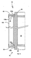
- a single fixture supports the connector member 55, the follower arm 65, and the valve arm 60 in the proper positions for assembly. Both ends of the connector member 70, 75 are then roller burnished substantially simultaneously or sequentially.
- Fig. 16 illustrates the result of this assembly method. Because the fixture properly locates the parts 55, 60, 65 the assembly does not rely on the shoulder locations to position one or both of the arms 60, 65. Thus, the roller burnishing produces two lips (an inner lip 135a and an outer lip 135b) that overlay each of the arms 60, 65. The two lips 135a, 135b cooperate to inhibit axial movement of the arms 60, 65 relative to the connector member 55.
- Figs 8 and 8a illustrate yet another method of attaching an arm 60 to the connector member 55.
- a single swage 155 is formed in the connector member 55.
- the swage 155 is a deformation of the reduced-diameter portion 80 of the connector member 55 that extends completely around the connector member 55.
- the arm 60 is placed onto the end of the connector member 55 until it abuts the first swage 155.
- a second swage 160 is then formed above the arm 60 to fix its axial position relative to the connector member 55 as illustrated in Fig. 8a . This process is repeated for the second arm 60.
- a fixture could be used to support the various components 53, 60, 65 in their desired positions, thereby allowing for the simultaneous connection of both arms 60, 65.
- the swages can be formed in any known manner so long as they can be positioned to retain the arms 60, 65. Compressing the connector member in an axial direction such that the material deforms in an outward (radial) direction can form swages.
- Compressing the connector member in an axial direction such that the material deforms in an outward (radial) direction can form swages.
- supplying high-pressure fluid to the interior of the connector member 55 while the connector member is restrained within a fixture forms swages.
- the high-pressure fluid acts to form the swages in the connector member 55 with the arms 60, 65 in their desired positions.
- One of ordinary skill will realize that many methods of forming swages are available and will function to form the lever arm 15 as described herein.
Landscapes
- Engineering & Computer Science (AREA)
- Mechanical Engineering (AREA)
- General Engineering & Computer Science (AREA)
- Mechanically-Actuated Valves (AREA)
- Valve-Gear Or Valve Arrangements (AREA)
- Valve Device For Special Equipments (AREA)
Priority Applications (1)
| Application Number | Priority Date | Filing Date | Title |
|---|---|---|---|
| PL04756911T PL1656494T3 (pl) | 2003-08-22 | 2004-07-14 | Dźwignia uruchamiająca zawór |
Applications Claiming Priority (2)
| Application Number | Priority Date | Filing Date | Title |
|---|---|---|---|
| US10/646,197 US6973903B2 (en) | 2003-08-22 | 2003-08-22 | Valve-operating lever |
| PCT/US2004/022370 WO2005024190A1 (en) | 2003-08-22 | 2004-07-14 | Valve-operating lever |
Publications (2)
| Publication Number | Publication Date |
|---|---|
| EP1656494A1 EP1656494A1 (en) | 2006-05-17 |
| EP1656494B1 true EP1656494B1 (en) | 2011-05-11 |
Family
ID=34194471
Family Applications (1)
| Application Number | Title | Priority Date | Filing Date |
|---|---|---|---|
| EP04756911A Expired - Lifetime EP1656494B1 (en) | 2003-08-22 | 2004-07-14 | Valve-operating lever |
Country Status (10)
| Country | Link |
|---|---|
| US (1) | US6973903B2 (pl) |
| EP (1) | EP1656494B1 (pl) |
| JP (1) | JP2007502936A (pl) |
| CN (2) | CN101487404B (pl) |
| AU (1) | AU2004271114B2 (pl) |
| BR (1) | BRPI0413796A (pl) |
| CA (1) | CA2534980C (pl) |
| PL (1) | PL1656494T3 (pl) |
| RU (1) | RU2317428C1 (pl) |
| WO (1) | WO2005024190A1 (pl) |
Families Citing this family (5)
| Publication number | Priority date | Publication date | Assignee | Title |
|---|---|---|---|---|
| US20060185636A1 (en) * | 2005-02-23 | 2006-08-24 | Gen Tek Technologies Marketing, Inc. | Manufacturing a rocker lever using cold forming and welding |
| US8550047B2 (en) * | 2009-06-09 | 2013-10-08 | Honda Motor Co., Ltd. | Valve control apparatus for internal combustion engine |
| RU2500896C1 (ru) * | 2012-04-11 | 2013-12-10 | Федеральное государственное бюджетное образовательное учреждение высшего профессионального образования "Елецкий государственный университет им. И.А. Бунина" | Газораспределительный механизм двс |
| RU2557828C1 (ru) * | 2014-02-10 | 2015-07-27 | Закрытое Акционерное Общество "Диаконт" | Устройство для управления клапаном |
| DE112018007399T5 (de) * | 2018-03-30 | 2020-12-17 | Honda Motor Co., Ltd. | Motor |
Family Cites Families (28)
| Publication number | Priority date | Publication date | Assignee | Title |
|---|---|---|---|---|
| US1404183A (en) * | 1919-11-18 | 1922-01-24 | Chester Machine Co Inc | Balanced cam shaft |
| GB156038A (en) | 1920-04-29 | 1921-01-06 | Coleman Boiler Appliance Compa | Improvements in flue-points or ferrules for connecting the ends of boiler tubes to end-plates |
| US1500166A (en) * | 1923-08-07 | 1924-07-08 | Cornelius W Van Ranst | Valve-operating mechanism |
| US3418985A (en) * | 1967-09-01 | 1968-12-31 | Hirose Kazuo | Rocker arm for internal combustion engines |
| US4369742A (en) * | 1977-01-24 | 1983-01-25 | Piston Powered Products A Division Of Rw Technologies, Inc. | Connecting rod for internal combustion engine |
| US4510897A (en) * | 1982-06-04 | 1985-04-16 | Motorenfabrik Hatz Gmbh & Co. Kg | Mechanism for actuating the valve rockers of an internal combustion engine |
| JPS60175807U (ja) * | 1984-05-01 | 1985-11-21 | 本田技研工業株式会社 | 内燃機関におけるsohc型動弁機構の潤滑装置 |
| DE3510442C3 (de) * | 1985-03-22 | 1994-07-14 | Lautenschlaeger Kg Karl | Möbelscharnier |
| US4903651A (en) * | 1987-10-29 | 1990-02-27 | Honda Giken Kogyo Kabushiki Kaisha | Rocker arm clearance removing device |
| SU1605006A1 (ru) * | 1989-01-25 | 1990-11-07 | В. К. Тюшкевич и О. И. Катана | Двигатель внутреннего сгорани с отключением цилиндров на холостом ходу |
| JP2849939B2 (ja) * | 1990-05-07 | 1999-01-27 | 本田技研工業株式会社 | Sohc型内燃機関 |
| US5022360A (en) * | 1990-10-15 | 1991-06-11 | Chrysler Corporation | Valve actuator for overhead camshaft engine |
| US5092634A (en) * | 1990-11-08 | 1992-03-03 | Parker Hannifin Corporation | Sealed tube block assembly |
| US5241932A (en) * | 1991-12-02 | 1993-09-07 | Ryobi Outdoor Products | Operator carried power tool having a four-cycle engine |
| US5197447A (en) * | 1992-04-14 | 1993-03-30 | Dick Leon B | Engine having valve stroke adjuster and fuel preheater |
| US5357917A (en) * | 1993-02-23 | 1994-10-25 | Ryobi Outdoor Products, Inc. | Stamped cam follower and method of making a stamped cam follower |
| DE4337594C2 (de) | 1993-11-04 | 2001-01-04 | Schaeffler Waelzlager Ohg | Bolzenbefestigung an Kipp- oder Schlepphebeln |
| CN2272487Y (zh) * | 1994-07-08 | 1998-01-14 | 财团法人工业技术研究院 | 一种四行程引擎之气门摇臂机构 |
| JP3464715B2 (ja) * | 1994-09-07 | 2003-11-10 | 本田技研工業株式会社 | Ohcエンジン |
| US5884593A (en) * | 1996-04-24 | 1999-03-23 | Tecumseh Products Company | Head and overhead camshaft assembly for an internal combustion engine |
| US5769499A (en) * | 1996-06-07 | 1998-06-23 | Lear Corporation | Motor vehicle seat |
| US6199527B1 (en) * | 1998-03-12 | 2001-03-13 | Nsk Ltd. | Sheet metal rocker arm, manufacturing method thereof, cam follower with said rocker arm, and assembling method thereof |
| US6349688B1 (en) * | 2000-02-18 | 2002-02-26 | Briggs & Stratton Corporation | Direct lever overhead valve system |
| US6782861B2 (en) * | 2001-02-09 | 2004-08-31 | Briggs & Stratton Corporation | Vacuum release mechanism |
| US6499453B1 (en) * | 2000-10-30 | 2002-12-31 | Tecumseh Products Company | Mid cam engine |
| US6634330B2 (en) * | 2000-11-16 | 2003-10-21 | Honda Giken Kogyo Kabushiki Kaisha | Valve system for engine |
| US6550435B1 (en) * | 2002-01-17 | 2003-04-22 | Ford Global Technologies, Llc | Variable valve timing adjustable finger follower assembly |
| US6739304B2 (en) * | 2002-06-28 | 2004-05-25 | Kohler Co. | Cross-flow cylinder head |
-
2003
- 2003-08-22 US US10/646,197 patent/US6973903B2/en not_active Expired - Fee Related
-
2004
- 2004-07-14 BR BRPI0413796-5A patent/BRPI0413796A/pt not_active IP Right Cessation
- 2004-07-14 EP EP04756911A patent/EP1656494B1/en not_active Expired - Lifetime
- 2004-07-14 CA CA002534980A patent/CA2534980C/en not_active Expired - Fee Related
- 2004-07-14 CN CN2009100058603A patent/CN101487404B/zh not_active Expired - Fee Related
- 2004-07-14 WO PCT/US2004/022370 patent/WO2005024190A1/en not_active Ceased
- 2004-07-14 CN CNB2004800239958A patent/CN100467834C/zh not_active Expired - Fee Related
- 2004-07-14 JP JP2006523842A patent/JP2007502936A/ja active Pending
- 2004-07-14 AU AU2004271114A patent/AU2004271114B2/en not_active Ceased
- 2004-07-14 RU RU2006109012/06A patent/RU2317428C1/ru not_active IP Right Cessation
- 2004-07-14 PL PL04756911T patent/PL1656494T3/pl unknown
Also Published As
| Publication number | Publication date |
|---|---|
| BRPI0413796A (pt) | 2006-11-07 |
| CN1839248A (zh) | 2006-09-27 |
| RU2317428C1 (ru) | 2008-02-20 |
| US6973903B2 (en) | 2005-12-13 |
| JP2007502936A (ja) | 2007-02-15 |
| PL1656494T3 (pl) | 2011-11-30 |
| RU2006109012A (ru) | 2007-09-27 |
| AU2004271114B2 (en) | 2010-03-25 |
| AU2004271114A1 (en) | 2005-03-17 |
| EP1656494A1 (en) | 2006-05-17 |
| WO2005024190A1 (en) | 2005-03-17 |
| US20050039714A1 (en) | 2005-02-24 |
| CA2534980C (en) | 2009-06-09 |
| CN101487404A (zh) | 2009-07-22 |
| CN101487404B (zh) | 2012-07-11 |
| CA2534980A1 (en) | 2005-03-17 |
| CN100467834C (zh) | 2009-03-11 |
Similar Documents
| Publication | Publication Date | Title |
|---|---|---|
| US7062852B2 (en) | Rocker arm | |
| JP3194982B2 (ja) | エンジンのバルブリフタの製造方法 | |
| EP1656494B1 (en) | Valve-operating lever | |
| EP0959232A2 (en) | Roller cam follower bearing shaft retention | |
| EP1160420A3 (en) | Engine valve assembly for internal combustion engine | |
| US6148780A (en) | Hydraulic element assembly | |
| US7392819B2 (en) | Method of setting the ball travel of a valve-lash-adjusting element | |
| US20050000314A1 (en) | Roller follower body | |
| US5269268A (en) | Tappet in an internal combustion engine and method of manufacturing the same | |
| JP2003240103A (ja) | カムフォロワ | |
| US20060157013A1 (en) | Method of making a rocker arm | |
| US7523729B2 (en) | Rocker assembly with adjustable swivel foot | |
| JPH1150814A (ja) | 動弁用プッシュロッド | |
| JP2001271614A (ja) | ロッカアーム及びその製造方法 | |
| US5706772A (en) | Tappet in an internal combustion engine and a method of manufacturing the tappet | |
| JP2761508B2 (ja) | 内燃機関用タペットとその製造方法 | |
| US20070039174A1 (en) | Manufacturing a rocker lever using cold forming and welding | |
| JP2536694Y2 (ja) | 内燃機関用タペット | |
| JPH07243311A (ja) | 内燃機関用タペット | |
| JPS6221683Y2 (pl) | ||
| EP0841472A1 (en) | Tappet in an internal combustion engine and a method of manufacturing the tappet | |
| Larson et al. | Ultra-light engine valve | |
| JPH0524363B2 (pl) | ||
| JPH0717904U (ja) | 内燃機関のバルブリフタ | |
| JPH061706U (ja) | 動弁用バルブリフタ |
Legal Events
| Date | Code | Title | Description |
|---|---|---|---|
| PUAI | Public reference made under article 153(3) epc to a published international application that has entered the european phase |
Free format text: ORIGINAL CODE: 0009012 |
|
| 17P | Request for examination filed |
Effective date: 20060210 |
|
| AK | Designated contracting states |
Kind code of ref document: A1 Designated state(s): CZ DE FR GB IT PL |
|
| DAX | Request for extension of the european patent (deleted) | ||
| RBV | Designated contracting states (corrected) |
Designated state(s): CZ DE FR GB IT PL |
|
| GRAP | Despatch of communication of intention to grant a patent |
Free format text: ORIGINAL CODE: EPIDOSNIGR1 |
|
| GRAS | Grant fee paid |
Free format text: ORIGINAL CODE: EPIDOSNIGR3 |
|
| GRAA | (expected) grant |
Free format text: ORIGINAL CODE: 0009210 |
|
| AK | Designated contracting states |
Kind code of ref document: B1 Designated state(s): CZ DE FR GB IT PL |
|
| REG | Reference to a national code |
Ref country code: GB Ref legal event code: FG4D |
|
| REG | Reference to a national code |
Ref country code: DE Ref legal event code: R096 Ref document number: 602004032643 Country of ref document: DE Effective date: 20110622 |
|
| REG | Reference to a national code |
Ref country code: PL Ref legal event code: T3 |
|
| PLBE | No opposition filed within time limit |
Free format text: ORIGINAL CODE: 0009261 |
|
| STAA | Information on the status of an ep patent application or granted ep patent |
Free format text: STATUS: NO OPPOSITION FILED WITHIN TIME LIMIT |
|
| 26N | No opposition filed |
Effective date: 20120214 |
|
| REG | Reference to a national code |
Ref country code: DE Ref legal event code: R097 Ref document number: 602004032643 Country of ref document: DE Effective date: 20120214 |
|
| PGFP | Annual fee paid to national office [announced via postgrant information from national office to epo] |
Ref country code: CZ Payment date: 20120626 Year of fee payment: 9 |
|
| PGFP | Annual fee paid to national office [announced via postgrant information from national office to epo] |
Ref country code: PL Payment date: 20120430 Year of fee payment: 9 |
|
| PGFP | Annual fee paid to national office [announced via postgrant information from national office to epo] |
Ref country code: GB Payment date: 20120711 Year of fee payment: 9 |
|
| PGFP | Annual fee paid to national office [announced via postgrant information from national office to epo] |
Ref country code: FR Payment date: 20120719 Year of fee payment: 9 Ref country code: IT Payment date: 20120713 Year of fee payment: 9 Ref country code: DE Payment date: 20120711 Year of fee payment: 9 |
|
| GBPC | Gb: european patent ceased through non-payment of renewal fee |
Effective date: 20130714 |
|
| REG | Reference to a national code |
Ref country code: FR Ref legal event code: ST Effective date: 20140331 |
|
| PG25 | Lapsed in a contracting state [announced via postgrant information from national office to epo] |
Ref country code: GB Free format text: LAPSE BECAUSE OF NON-PAYMENT OF DUE FEES Effective date: 20130714 Ref country code: CZ Free format text: LAPSE BECAUSE OF NON-PAYMENT OF DUE FEES Effective date: 20130714 Ref country code: DE Free format text: LAPSE BECAUSE OF NON-PAYMENT OF DUE FEES Effective date: 20140201 |
|
| REG | Reference to a national code |
Ref country code: DE Ref legal event code: R119 Ref document number: 602004032643 Country of ref document: DE Effective date: 20140201 |
|
| PG25 | Lapsed in a contracting state [announced via postgrant information from national office to epo] |
Ref country code: IT Free format text: LAPSE BECAUSE OF NON-PAYMENT OF DUE FEES Effective date: 20130714 Ref country code: FR Free format text: LAPSE BECAUSE OF NON-PAYMENT OF DUE FEES Effective date: 20130731 |
|
| REG | Reference to a national code |
Ref country code: PL Ref legal event code: LAPE |
|
| PG25 | Lapsed in a contracting state [announced via postgrant information from national office to epo] |
Ref country code: PL Free format text: LAPSE BECAUSE OF NON-PAYMENT OF DUE FEES Effective date: 20130714 |