EP1656502B1 - Pompe a vis sans fin excentrique munie d'un rotor resistant a l'erosion - Google Patents
Pompe a vis sans fin excentrique munie d'un rotor resistant a l'erosion Download PDFInfo
- Publication number
- EP1656502B1 EP1656502B1 EP04764133A EP04764133A EP1656502B1 EP 1656502 B1 EP1656502 B1 EP 1656502B1 EP 04764133 A EP04764133 A EP 04764133A EP 04764133 A EP04764133 A EP 04764133A EP 1656502 B1 EP1656502 B1 EP 1656502B1
- Authority
- EP
- European Patent Office
- Prior art keywords
- eccentric screw
- motor according
- screw pump
- eccentric
- screw motor
- Prior art date
- Legal status (The legal status is an assumption and is not a legal conclusion. Google has not performed a legal analysis and makes no representation as to the accuracy of the status listed.)
- Expired - Lifetime
Links
- 230000003628 erosive effect Effects 0.000 title description 7
- 239000000463 material Substances 0.000 claims abstract description 16
- 238000005260 corrosion Methods 0.000 claims abstract description 7
- 230000007797 corrosion Effects 0.000 claims abstract description 7
- 238000005299 abrasion Methods 0.000 claims abstract description 6
- 239000002184 metal Substances 0.000 claims description 30
- 238000000034 method Methods 0.000 claims description 22
- 229910000831 Steel Inorganic materials 0.000 claims description 18
- 239000010959 steel Substances 0.000 claims description 18
- 238000004804 winding Methods 0.000 claims description 10
- 230000002093 peripheral effect Effects 0.000 claims description 7
- 238000004519 manufacturing process Methods 0.000 claims description 4
- 230000008878 coupling Effects 0.000 claims description 3
- 238000010168 coupling process Methods 0.000 claims description 3
- 238000005859 coupling reaction Methods 0.000 claims description 3
- 239000007787 solid Substances 0.000 claims description 2
- 150000001875 compounds Chemical class 0.000 claims 3
- 238000003825 pressing Methods 0.000 claims 1
- 210000001503 joint Anatomy 0.000 description 7
- 239000010935 stainless steel Substances 0.000 description 4
- 229910001220 stainless steel Inorganic materials 0.000 description 4
- 238000003466 welding Methods 0.000 description 4
- 238000005096 rolling process Methods 0.000 description 3
- 238000001816 cooling Methods 0.000 description 2
- 238000006073 displacement reaction Methods 0.000 description 2
- 239000013536 elastomeric material Substances 0.000 description 2
- 239000011347 resin Substances 0.000 description 2
- 229920005989 resin Polymers 0.000 description 2
- 229910000851 Alloy steel Inorganic materials 0.000 description 1
- 244000043261 Hevea brasiliensis Species 0.000 description 1
- 230000004323 axial length Effects 0.000 description 1
- 239000011248 coating agent Substances 0.000 description 1
- 238000000576 coating method Methods 0.000 description 1
- 238000010276 construction Methods 0.000 description 1
- 238000011161 development Methods 0.000 description 1
- 230000018109 developmental process Effects 0.000 description 1
- 230000000694 effects Effects 0.000 description 1
- 230000001747 exhibiting effect Effects 0.000 description 1
- 239000000945 filler Substances 0.000 description 1
- 230000005484 gravity Effects 0.000 description 1
- 229910001092 metal group alloy Inorganic materials 0.000 description 1
- 238000012986 modification Methods 0.000 description 1
- 230000004048 modification Effects 0.000 description 1
- 229920003052 natural elastomer Polymers 0.000 description 1
- 229920001194 natural rubber Polymers 0.000 description 1
- 239000002245 particle Substances 0.000 description 1
- 230000035515 penetration Effects 0.000 description 1
- 238000007747 plating Methods 0.000 description 1
- 239000000843 powder Substances 0.000 description 1
- 230000002250 progressing effect Effects 0.000 description 1
- 239000003566 sealing material Substances 0.000 description 1
- 239000011265 semifinished product Substances 0.000 description 1
- 238000005482 strain hardening Methods 0.000 description 1
- 229920002994 synthetic fiber Polymers 0.000 description 1
Images
Classifications
-
- F—MECHANICAL ENGINEERING; LIGHTING; HEATING; WEAPONS; BLASTING
- F04—POSITIVE - DISPLACEMENT MACHINES FOR LIQUIDS; PUMPS FOR LIQUIDS OR ELASTIC FLUIDS
- F04C—ROTARY-PISTON, OR OSCILLATING-PISTON, POSITIVE-DISPLACEMENT MACHINES FOR LIQUIDS; ROTARY-PISTON, OR OSCILLATING-PISTON, POSITIVE-DISPLACEMENT PUMPS
- F04C2/00—Rotary-piston machines or pumps
- F04C2/08—Rotary-piston machines or pumps of intermeshing-engagement type, i.e. with engagement of co-operating members similar to that of toothed gearing
- F04C2/10—Rotary-piston machines or pumps of intermeshing-engagement type, i.e. with engagement of co-operating members similar to that of toothed gearing of internal-axis type with the outer member having more teeth or tooth-equivalents, e.g. rollers, than the inner member
- F04C2/107—Rotary-piston machines or pumps of intermeshing-engagement type, i.e. with engagement of co-operating members similar to that of toothed gearing of internal-axis type with the outer member having more teeth or tooth-equivalents, e.g. rollers, than the inner member with helical teeth
- F04C2/1071—Rotary-piston machines or pumps of intermeshing-engagement type, i.e. with engagement of co-operating members similar to that of toothed gearing of internal-axis type with the outer member having more teeth or tooth-equivalents, e.g. rollers, than the inner member with helical teeth the inner and outer member having a different number of threads and one of the two being made of elastic materials, e.g. Moineau type
-
- F—MECHANICAL ENGINEERING; LIGHTING; HEATING; WEAPONS; BLASTING
- F04—POSITIVE - DISPLACEMENT MACHINES FOR LIQUIDS; PUMPS FOR LIQUIDS OR ELASTIC FLUIDS
- F04C—ROTARY-PISTON, OR OSCILLATING-PISTON, POSITIVE-DISPLACEMENT MACHINES FOR LIQUIDS; ROTARY-PISTON, OR OSCILLATING-PISTON, POSITIVE-DISPLACEMENT PUMPS
- F04C2230/00—Manufacture
- F04C2230/20—Manufacture essentially without removing material
- F04C2230/23—Manufacture essentially without removing material by permanently joining parts together
- F04C2230/231—Manufacture essentially without removing material by permanently joining parts together by welding
-
- F—MECHANICAL ENGINEERING; LIGHTING; HEATING; WEAPONS; BLASTING
- F04—POSITIVE - DISPLACEMENT MACHINES FOR LIQUIDS; PUMPS FOR LIQUIDS OR ELASTIC FLUIDS
- F04C—ROTARY-PISTON, OR OSCILLATING-PISTON, POSITIVE-DISPLACEMENT MACHINES FOR LIQUIDS; ROTARY-PISTON, OR OSCILLATING-PISTON, POSITIVE-DISPLACEMENT PUMPS
- F04C2240/00—Components
- F04C2240/20—Rotors
-
- Y—GENERAL TAGGING OF NEW TECHNOLOGICAL DEVELOPMENTS; GENERAL TAGGING OF CROSS-SECTIONAL TECHNOLOGIES SPANNING OVER SEVERAL SECTIONS OF THE IPC; TECHNICAL SUBJECTS COVERED BY FORMER USPC CROSS-REFERENCE ART COLLECTIONS [XRACs] AND DIGESTS
- Y10—TECHNICAL SUBJECTS COVERED BY FORMER USPC
- Y10T—TECHNICAL SUBJECTS COVERED BY FORMER US CLASSIFICATION
- Y10T29/00—Metal working
- Y10T29/49—Method of mechanical manufacture
- Y10T29/49229—Prime mover or fluid pump making
- Y10T29/49236—Fluid pump or compressor making
- Y10T29/49242—Screw or gear type, e.g., Moineau type
-
- Y—GENERAL TAGGING OF NEW TECHNOLOGICAL DEVELOPMENTS; GENERAL TAGGING OF CROSS-SECTIONAL TECHNOLOGIES SPANNING OVER SEVERAL SECTIONS OF THE IPC; TECHNICAL SUBJECTS COVERED BY FORMER USPC CROSS-REFERENCE ART COLLECTIONS [XRACs] AND DIGESTS
- Y10—TECHNICAL SUBJECTS COVERED BY FORMER USPC
- Y10T—TECHNICAL SUBJECTS COVERED BY FORMER US CLASSIFICATION
- Y10T29/00—Metal working
- Y10T29/49—Method of mechanical manufacture
- Y10T29/49826—Assembling or joining
- Y10T29/49863—Assembling or joining with prestressing of part
- Y10T29/49865—Assembling or joining with prestressing of part by temperature differential [e.g., shrink fit]
Definitions
- the pump or the motor has a stator with a continuous helical opening in which the rotor rolls in the displacement mode.
- the stator forms a cylindrical tube which is provided with an elastomeric lining.
- the elastomeric lining itself constitutes the wall of the through-hole and acts as a seal against the stator.
- the stator is composed of a core element and a shell formed around it.
- the jacket is cold formed starting from a cylindrical tube in the helical shape. This preserves the original cylindrical Tube not only the helical shape as it is required for the rotor, but the tube is thus firmly connected to the core element.
- the thread valleys of the jacket of the stator are firmly and frictionally on the core element.
- the carrier element may still be provided with longitudinal ribs.
- the known rotor is inexpensive to produce in very large quantities. Lengths of up to 6 meters can easily be achieved without the need for a chipping rework of the surface of the stator.
- the surface of the rotor is very smooth and sufficiently dimensionally stable.
- the core element present in the shell prevents the rotor from becoming desorbed when pressurized, which would lead to a pitch error between the stator and rotor and the consequent leakage.
- the steel material hitherto used for the known rotor is not strong enough for a number of applications with regard to the abrasion occurring and, for some applications, also not sufficiently resistant to corrosion.
- the known rotor is not characterized by a sufficient erosion resistance. Erosion should not only be understood to mean the removal by corrosion, but also the removal by vibratory grinding of the material being conveyed on the surface.
- stator with a jacket, which also shows a helical shape similar to a helical shape of the through hole.
- the elastomeric lining which in turn serves as a sealing material, in these cases has virtually a nearly constant wall thickness.
- the method is characterized by the features of claim 23.
- the rotor is sandwiched. It consists of a radially inner layer and a radially outer layer, wherein the radially outer layer is specially adapted to the higher erosion resistance. It may be more resistant to abrasion or corrosion, or both, than the radially inner layer.
- the radially inner layer can be selected primarily from the viewpoint of strength and cost, so that with a very thin radial outer layer the death is found.
- a very homogeneous structure of the rotor can be achieved if the inner tube is a seamless tube. Inhomogeneities, as they would otherwise occur during welding, thereby avoided. Such inhomogeneities could continue as a form error to the outside.
- a wound tube is also possible.
- the tube is preferably laser welded. The helix should run in opposite directions to the helix of the outer layer.
- the inner layer, or the inner tube consists of an easily deformable steel, which is well suited to dissipate the forces occurring and can be cold formed in a useful manner.
- the outer layer may consist of an attached tube.
- such a solution is only suitable for rotors with a short overall length.
- the metal strip is wound on impact in such a way that the individual turns adjoin each other without a gap.
- a particularly good arrangement is achieved if before the cold forming the helical joint, on which the turns abut each other, is welded.
- the welding is done by means of laser.
- Stainless steel V2A, V4A steel or other abrasion-resistant steels may be considered as external material. Since these have a much higher specific gravity than normal steel, the two-layer construction also means a weight saving compared to a rotor made only of stainless steel. This certainly plays a role in rotors with a length of up to 6 meters.
- the strength of the rotor can be improved if it has a core element.
- the rotor may be molded around the core member to provide a good bond with the core member.
- the core element prevents long rotation of the rotor under load.
- additional torque can be introduced over the length of the rotor.
- the substantially Rotationsssymentwitz and not helically deformed core is better suited.
- the core element may itself be tubular or solid.
- the gap between the tube or shell of the rotor and the core element can either be left blank or filled with a mass.
- a cylindrical tube is first provided.
- the tube is covered with a metal layer, so that a double-walled structure is obtained.
- the double-walled structure which is still cylindrical, helically deformed.
- the coating of the cylindrical tube with the outer layer is very simple and can also be done simply because of the simple geometric shape of the tube provided.
- outer layer Since the outer layer must be applied only with a smaller wall thickness, because the stability of the rotor may be generated in the first place of the inner tube, materials can be used for the outer layer, which would no longer be cold to deform at high wall thickness ,
- a seamless tube is used in the method according to the invention.
- the seamless tube has expediently a metallically bright surface, so that the connection of the outer layer with the tube by the cold forming is not hindered by oxydschreibtex.
- the outer metal layer consists in the simplest case of a metal strip which is wound onto the tube.
- the metal strip can be heated immediately before the contact point before being wound up. The subsequent cooling ensures a shrinkage process that holds the metal strip particularly firmly on the surface of the tube.
- the butt joint between adjacent turns is suitably welded to prevent penetration of particles.
- the resulting double-walled structure is cold formed.
- the outer layer joins the inner tube, similar to the case of leafing.
- the connection is therefore particularly durable and will not open even with temperature changes.
- a core element may be inserted before forming the coated tube.
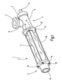
- the eccentric screw pump 1 shows a schematic, perspective illustration of an eccentric screw pump 1 according to the invention.
- the eccentric screw pump 1 includes a pump head 2, a stator 3 in which a rotor 4 illustrated in FIG. 2 rotates, and a connection head 5.
- the pump head 2 has a substantially cylindrical housing 6 which is provided at one end with a cover 7, through which a drive shaft 8 is guided outwardly sealed.
- a connection piece 9 which ends at a mounting flange 11.
- a coupling piece to the drive shaft 8 which is connected to a drive motor, not shown, with the rotor 4 rotatably to couple.
- the front end of the housing 6 remote from the cover 7 is provided with a clamping flange 12 whose diameter is greater than the diameter of the substantially cylindrical housing 6.
- the clamping flange 12 includes a stepped bore 13 which is aligned with the interior of the housing 6. In the stepped bore an unrecognizable investment shoulder is formed, against which the stator 3 is pressed with one end.
- connection head 5 has a cooperating with the clamping flange 12 clamping flange 14, which also includes a stepped bore in which the other end of the stator 3 is inserted. With the stepped bore a wegsumde pipe 15 is aligned.
- the stator 3 is tightened sealed by means of a total of 4 tie rods 16.
- the two clamping flanges 12 and 14 are provided with four mutually aligned holes 17 which lie on a pitch circle, which is larger than the outer diameter of the housing 6 and the tube 15. Through these holes 17 lead rod-shaped tie rod 16 therethrough.
- nuts 18 are screwed onto the tie rods, with the help of the two clamping flanges 12 and 14 are tightened towards each other.
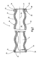
- the stator 3 is, as shown in FIG. 2 shows a tubular jacket 19 with a constant wall thickness, which surrounds an interior space 20.
- the jacket 19 is made of steel, a steel alloy, light metal or a light metal alloy. It is shaped so that its inner wall 21 gets the outer shape of a multi-start screw. Its outer side 22 has a correspondingly similar shape with a diameter corresponding to the wall thickness of the shell 19 is greater than the diameter of the interior of the shell 19th
- the jacket 19 terminates at its ends with end faces 23 and 24 which extend at right angles to its longitudinal axis 25.
- the longitudinal axis 25 is the axis of the interior 20.
- the interior 20 has the shape a double-threaded screw.
- the cross section which is surrounded by the outer surface 22, each seen at right angles to the longitudinal axis 25, the shape of an oval, similar to a racetrack.
- the ends can also be formed into cylindrical tubes.
- the end ring 26 includes a through hole 27, which coincides with the course of the outer surface 22 over the length of the end ring 26.
- the end ring 26 acts in the broadest sense as a nut, which is screwed onto the thread, which is defined by the jacket 19.
- the length of the thread corresponds to the thickness of the end ring 26.
- end ring 26 Radially outwardly, the end ring 26 is bounded by a cylindrical surface 28 which merges in the axial direction into a plane surface 29 facing away from the shell 19.
- the liner 32 is made of an elastically resilient, preferably elastomeric material, such as natural rubber or synthetic material, and has approximately the same wall thickness at each location.
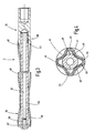
- the rotor 4 is composed of a core element 33, a rotor shell 34 and a coupling head 35.
- the core element 33 is in the illustrated embodiment, a thick-walled steel tube with an at least originally cylindrical outer peripheral surface 36 and a continuous cylindrical interior 37.
- the core element 33 is straight and therefore tubular in shape, because the interior does not provide any appreciable contribution to the strength in question, but only adds weight. But it can also be massive.
- the core member 33 At its right in Fig. 3 end of the core member 33 is provided with a threaded pin 38. At the opposite end, the core member 33 includes a threaded bore 39.
- the jacket 34 of the rotor 4 is also a tube with an inner wall 40 and an outer surface 41.
- the outer surface 41 forms a thread that continues over the entire axial length of the jacket 34. It begins at 42 and ends at 43.
- the number of turns of the thread formed by the outer surface 41 is one less than the number of turns of the through-hole 20 in the stator. 3
- the rotor 4 in the embodiment shown has a four-start thread, i. along the mantle 34 extend helically a total of four strips. Since the passage opening 20 is correspondingly five continuous, forms the five-start thread in the through hole 20 a total of five helically extending strips of elastomeric material.
- the rotor shell 34 has two layers and consists of an inner layer 44 and an outer layer located thereon Layer 45.
- the inner layer 44 consists of an originally cylindrical steel tube with good ductility and a strength suitable for the application.
- the outer layer 45 consists of an erosion-resistant material, that is, a material that is little worn or abraded by the medium to be pumped and / or that is chemically attacked by the medium to be pumped little.
- a suitable material is for example stainless steel such as a V2A or a V4A.
- the wall thickness of the inner layer 44 is between 1 mm and 5 mm, while the wall thickness of the outer layer 45 can be between 1 mm and also 5 mm. The production of this rotor 4 is explained below with reference to FIG 5.
- the shell 34 is, as already mentioned, tubular, which is why the inner surface 40 of the outer surface 41 follows at a constant distance.
- the dimensions of the cylindrical straight tube, from which the jacket 34 is cold worked, are selected such that after the final deformation to the helical shape of the shell 34 with its inner peripheral surface 40 in the region of the thread valleys 47 (relative to the outer contour), the outer peripheral surface 36th of the core element 33 at least touched.
- the semifinished product as mentioned, from which the jacket 34 is made, a cylindrical tube whose diameter is larger than the outer diameter of the core member 33, between the core member 33 and the shell 34 helically extending gaps 49.
- the number of these helical spaces 49 is equal to the number of thread crests 46, which can be seen in the cross section of the rotor 4 in the circumferential direction.
- these spaces 49 can either remain empty or filled with a mass. This mass can e.g. Resin or filled with light metal powder resin.
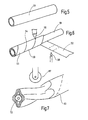
- the production method of the rotor 4 consisting of the layers 44 and 45 is illustrated in a very schematic manner in FIGS. 5 to 7.
- the steel tube 51 is wound on the outside with a metal strip 52, which later forms the outer layer 45.
- the metal band 52 is a band of a corresponding stainless steel or other steel.
- the band 42 is wound on the outside of the steel tube 51 as a catchy screw. In this case, it forms adjacent turns 53, which are separated by a respective helically extending butt joint 54. The winding of the metal strip 52 is done so that the butt joint 54 is closed as possible.
- the butt joint 54 is welded during winding or in a separate step by means of a laser beam 55 and filler material to achieve a smooth, homogeneous cylindrical surface. Other welding methods are also possible. It can be welded through to connect the band 52 in the region of the butt joint 54 with the support tube 51 cohesively.
- the metal strip 52 Immediately before the metal strip 52 impinges on the tube 51, it is heated, for example by means of a gas flame 56 or inductively. This ensures that the metal strip 52 generates a considerable tension in the circumferential direction after winding on the tube 51 and the cooling.
- the core element 33 is inserted according to FIG. Subsequently, the structure by cold deformation, for example, rolls by means of a variety of rollers, of which only one is indicated at 57, brought in the desired helical shape.
- the metal strip 52 connects very intimately with the outer surface of the underlying steel tube 51st
- the metal strip 52 forms, after the step of Figure 6 is completed, on the metal steel tube 51, a second, outer tube which sits firmly and under tension in the circumferential direction frictionally on the outer peripheral surface of the tube 51.
- the two tubes namely the tube formed by winding and the seamless, inner steel tube are so firmly connected to each other after winding that they are no longer separated.
- the subsequent rolling process according to FIG. 7 ensures an even more intimate bond, which at least to a certain extent resembles the plating of a metal layer.
- the outer, made by winding pipe does not separate from the underlying tube 51. Rather, both are formed together in the desired helical shape, at the same time also the intimate connection with the core element 33 is produced.
- metal bands can be wound up as a multi-start screw. Furthermore, the winding process can be repeated to create several layers one above the other.
Landscapes
- Engineering & Computer Science (AREA)
- Mechanical Engineering (AREA)
- General Engineering & Computer Science (AREA)
- Rotary Pumps (AREA)
- Details And Applications Of Rotary Liquid Pumps (AREA)
Claims (32)
- Pompe à vis excentrique ou moteur à vis excentrique (1),
avec un stator (3) qui présente un alésage de stator (20) traversant, conformé en hélice,
avec un rotor hélicoïdal (4) adapté à l'alésage de stator (20) qui présente un tube (34) façonné en hélice,
caractérisée par le fait que le tube (34) est composé d'une couche intérieure (44) et d'au moins une couche extérieure (45) qui sont façonnées conjointement pour obtenir la forme en hélice, la couche extérieure étant formée d'un matériau différent de celui de la couche intérieure (44) et
que le tube présente une tête de couplage (35) qui est liée de manière rigide en rotation au rotor (4). - Pompe à vis excentrique ou moteur à vis excentrique selon la revendication 1, caractérisée par le fait que le matériau de la couche extérieure (45) présente une résistance à l'abrasion et/ou à la corrosion supérieure à celle du matériau de la couche intérieure (44).
- Pompe à vis excentrique ou moteur à vis excentrique selon la revendication 1, caractérisée par le fait que la couche intérieure (44) est formée d'un tube (51) sans soudure.
- Pompe à vis excentrique ou moteur à vis excentrique selon la revendication 1, caractérisée par le fait que la couche intérieure (44) est en acier.
- Pompe à vis excentrique ou moteur à vis excentrique selon la revendication 1, caractérisée par le fait que la couche extérieure (45) est formée d'au moins une bande de métal (52).
- Pompe à vis excentrique ou moteur à vis excentrique selon la revendication 1, caractérisée par le fait que la bande de métal (52), au nombre d'au moins une, de la couche extérieure (45) est enroulée en hélice sur la couche intérieure (44).
- Pompe à vis excentrique ou moteur à vis excentrique selon la revendication 6, caractérisée par le fait que les joints d'assemblage (54) entre des spires (53) contiguës de la bande de métal (52) enroulée, au nombre d'au moins une, sont soudés.
- Pompe à vis excentrique ou moteur à vis excentrique selon la revendication 7, caractérisée par le fait que les joints d'assemblage (54) sont soudés par laser.
- Pompe à vis excentrique ou moteur à vis excentrique selon la revendication 1, caractérisée par le fait que le matériau de la couche extérieure (45) est un acier résistant à la corrosion et/ou à résistance élevée à l'abrasion.
- Pompe à vis excentrique ou moteur à vis excentrique selon la revendication 9, caractérisée par le fait que l'acier est choisi parmi les matériaux V2A, V4A.
- Pompe à vis excentrique ou moteur à vis excentrique selon la revendication 1, caractérisée par le fait que le rotor (4) contient un coeur (33) qui est lié par adhérence et/ou par obstacle au tube (34).
- Pompe à vis excentrique ou moteur à vis excentrique selon la revendication 11, caractérisée par le fait que le tube (34) est lié par obstacle au coeur (33) dans la région des fonds de filet (47), le coeur (33) étant repoussé uniquement dans la région des fonds de filet (47) du tube (34) et formant au moins une gorge (48) aplatie en hélice.
- Pompe à vis excentrique ou moteur à vis excentrique selon la revendication 11, caractérisée par le fait qu'il existe entre le coeur (33) et le tube (34) au moins un espace (49) qui s'étend en forme d'hélice.
- Pompe à vis excentrique ou moteur à vis excentrique selon la revendication 11, caractérisée par le fait que le coeur (33) est tubulaire.
- Pompe à vis excentrique ou moteur à vis excentrique selon la revendication 11, caractérisée par le fait que le coeur (33) est massif.
- Pompe à vis excentrique ou moteur à vis excentrique selon la revendication 13, caractérisée par le fait que l'espace (49) en forme d'hélice, au nombre d'au moins un, est rempli d'une masse.
- Pompe à vis excentrique ou moteur à vis excentrique selon la revendication 13, caractérisée par le fait que l'espace (49) en forme d'hélice, au nombre d'au moins un, est vide.
- Pompe à vis excentrique ou moteur à vis excentrique selon la revendication 1, caractérisée par le fait que le stator (3) présente une paroi (32) qui est formée d'une masse d'élastomère.
- Pompe à vis excentrique ou moteur à vis excentrique selon la revendication 1, caractérisée par le fait que le stator (3) est formé d'une enveloppe (19) pourvue d'un revêtement d'élastomère.
- Pompe à vis excentrique ou moteur à vis excentrique selon la revendication 19, caractérisée par le fait que la masse d'élastomère, sur une grande partie de la longueur du stator (3), présente une épaisseur essentiellement constante.
- Pompe à vis excentrique ou moteur à vis excentrique selon la revendication 1, caractérisée par le fait que l'enveloppe (19) présente une forme d'hélice qui est similaire à celle de l'alésage de stator (20).
- Pompe à vis excentrique ou moteur à vis excentrique selon la revendication 1, caractérisée par le fait que l'enveloppe (19) a une forme cylindrique et le revêtement (32) présente une surface périphérique extérieure cylindrique.
- Procédé pour fabriquer un rotor d'une pompe à vis excentrique ou d'un moteur à vis excentrique avec un stator (3) qui présente un alésage de stator (20) traversant conformé en hélice, comportant les étapes de procédé suivantes:on part d'un tube (51) cylindrique,on entoure le tube (51) d'une couche de métal (52) de manière à obtenir un corps à paroi double (51, 52),on façonne le corps (51, 52) à paroi double pour obtenir la conformation en hélice du rotor (4).
- Procédé selon la revendication 23, caractérisé par le fait que le tube cylindrique (51) est un tube sans soudure.
- Procédé selon la revendication 24, caractérisé par le fait que le tube cylindrique (51) présente une surface périphérique extérieure métallique sans revêtement.
- Procédé selon la revendication 23, caractérisé par le fait que la couche de métal est formée d'au moins une bande de métal (52).
- Procédé selon la revendication 26, caractérisé par le fait que la bande de métal (52) est enroulée sur le tube (51) intérieur de manière telle que les spires (53) se touchent essentiellement sans jeu.
- Procédé selon la revendication 23, caractérisé par le fait que le joint d'assemblage (54) entre des spires (53) contiguës est soudé.
- Procédé selon la revendication 23, caractérisé par le fait que la bande de métal (52) est réchauffée en continu avant son enroulement sur le tube (51).
- Procédé selon la revendication 23, caractérisé par le fait que le corps (51, 52) à paroi double est façonné à froid.
- Procédé selon la revendication 30, caractérisé par le fait qu'avant le façonnage à froid on insère un coeur (33) dans le corps (51, 52) à double paroi.
- Procédé selon la revendication 31, caractérisé par le fait que le coeur (33) présente des nervures longitudinales.
Applications Claiming Priority (2)
| Application Number | Priority Date | Filing Date | Title |
|---|---|---|---|
| DE10338632A DE10338632B4 (de) | 2003-08-22 | 2003-08-22 | Exzenterschneckenpumpe mit erosionsfestem Rotor |
| PCT/EP2004/009141 WO2005021971A1 (fr) | 2003-08-22 | 2004-08-14 | Pompe a vis sans fin excentrique munie d'un rotor resistant a l'erosion |
Publications (2)
| Publication Number | Publication Date |
|---|---|
| EP1656502A1 EP1656502A1 (fr) | 2006-05-17 |
| EP1656502B1 true EP1656502B1 (fr) | 2008-02-06 |
Family
ID=34201855
Family Applications (1)
| Application Number | Title | Priority Date | Filing Date |
|---|---|---|---|
| EP04764133A Expired - Lifetime EP1656502B1 (fr) | 2003-08-22 | 2004-08-14 | Pompe a vis sans fin excentrique munie d'un rotor resistant a l'erosion |
Country Status (10)
| Country | Link |
|---|---|
| US (1) | US7909591B2 (fr) |
| EP (1) | EP1656502B1 (fr) |
| AT (1) | ATE385544T1 (fr) |
| BR (1) | BRPI0413690B1 (fr) |
| CA (1) | CA2535870C (fr) |
| DE (2) | DE10338632B4 (fr) |
| ES (1) | ES2300811T3 (fr) |
| PT (1) | PT1656502E (fr) |
| RU (1) | RU2340793C2 (fr) |
| WO (1) | WO2005021971A1 (fr) |
Families Citing this family (11)
| Publication number | Priority date | Publication date | Assignee | Title |
|---|---|---|---|---|
| US8182252B2 (en) | 2007-10-30 | 2012-05-22 | Moyno, Inc. | Progressing cavity pump with split stator |
| US8215014B2 (en) * | 2007-10-31 | 2012-07-10 | Moyno, Inc. | Method for making a stator |
| US20110058930A1 (en) * | 2009-09-04 | 2011-03-10 | Robbins & Myers Energy Systems L.P. | Motor/pump with spiral wound stator tube |
| DE102010010269C5 (de) | 2010-03-05 | 2023-11-16 | Mercedes-Benz Group AG | Verfahren zum Herstellen eines Statorträgers |
| US9441627B2 (en) | 2012-11-01 | 2016-09-13 | National Oilwell Varco, L.P. | Lightweight and flexible rotors for positive displacement devices |
| DE102013102979B4 (de) | 2013-03-22 | 2017-03-30 | Wilhelm Kächele GmbH | Exzenterschneckenmaschine |
| DE202013004219U1 (de) * | 2013-05-06 | 2013-05-17 | SGF SüDDEUTSCHE GELENKSCHEIBENFABRIK GMBH & CO. KG | Stator für eine Förderpumpe |
| FR3081519B1 (fr) * | 2018-05-23 | 2020-05-29 | Pcm Technologies | Element de stator d'une pompe a cavites progressives et pompe a cavites progressives |
| CN109405620A (zh) * | 2018-11-14 | 2019-03-01 | 浙江中达特钢股份有限公司 | 一种高效不锈钢无缝换热管 |
| US11795946B2 (en) | 2020-03-04 | 2023-10-24 | Schlumberger Technology Corporation | Mud motor rotor with core and shell |
| CN111396311A (zh) * | 2020-04-26 | 2020-07-10 | 陕西理工大学 | 一种空心螺杆转子及其加工方法 |
Family Cites Families (12)
| Publication number | Priority date | Publication date | Assignee | Title |
|---|---|---|---|---|
| US2028407A (en) * | 1932-04-29 | 1936-01-21 | Moineau Rene Joseph Louis | Gear mechanism |
| US2464011A (en) * | 1946-11-29 | 1949-03-08 | Fmc Corp | Helical hollow rotor pump |
| DE1816462A1 (de) * | 1968-12-21 | 1970-07-02 | Netzsch Maschinenfabrik | Rotor fuer eine Schraubenpumpe |
| DE2240423A1 (de) * | 1972-08-17 | 1974-03-07 | Hermetic Pumpen Gmbh | Foerdereinrichtung, insbesondere foerderpumpe |
| DE2918602A1 (de) * | 1979-05-09 | 1980-11-20 | Josef Ing Grad Zeitvogel | Verfahren zur herstellung und nach diesem verfahren hergestellte, hohle exzenterschnecke fuer exzenterschneckenpumpen |
| DE3604680A1 (de) * | 1985-02-26 | 1986-09-18 | Jürgen 5200 Siegburg Beckschulte | Laeufer fuer eine exzenterschneckenpumpe |
| DE19852380C2 (de) * | 1998-11-13 | 2001-11-22 | Wilhelm Kaechele Gmbh Elastome | Schnecke für eine Exzenterschneckenpumpe oder einen Untertagebohrmotor |
| DE19950257B4 (de) * | 1999-10-18 | 2013-01-17 | Wilhelm Kächele GmbH Elastomertechnik | Exzenterschneckenpumpe mit vollausgekleidetem Stator |
| JP4627346B2 (ja) * | 2000-03-31 | 2011-02-09 | 本田技研工業株式会社 | ブレーキディスク |
| RU2169820C1 (ru) * | 2000-05-31 | 2001-06-27 | Открытое акционерное общество Научно-производственное объединение "Буровая техника" | Ротор винтовой забойной гидромашины |
| US6604922B1 (en) * | 2002-03-14 | 2003-08-12 | Schlumberger Technology Corporation | Optimized fiber reinforced liner material for positive displacement drilling motors |
| RU2228443C1 (ru) * | 2003-03-11 | 2004-05-10 | Общество с ограниченной ответственностью фирма "Радиус-Сервис" | Ротор винтовой гидромашины |
-
2003
- 2003-08-22 DE DE10338632A patent/DE10338632B4/de not_active Expired - Fee Related
-
2004
- 2004-08-14 AT AT04764133T patent/ATE385544T1/de active
- 2004-08-14 WO PCT/EP2004/009141 patent/WO2005021971A1/fr not_active Ceased
- 2004-08-14 EP EP04764133A patent/EP1656502B1/fr not_active Expired - Lifetime
- 2004-08-14 DE DE502004006140T patent/DE502004006140D1/de not_active Expired - Lifetime
- 2004-08-14 BR BRPI0413690A patent/BRPI0413690B1/pt not_active IP Right Cessation
- 2004-08-14 PT PT04764133T patent/PT1656502E/pt unknown
- 2004-08-14 ES ES04764133T patent/ES2300811T3/es not_active Expired - Lifetime
- 2004-08-14 RU RU2006109022/06A patent/RU2340793C2/ru not_active IP Right Cessation
- 2004-08-14 CA CA2535870A patent/CA2535870C/fr not_active Expired - Fee Related
- 2004-08-14 US US10/569,247 patent/US7909591B2/en not_active Expired - Fee Related
Also Published As
| Publication number | Publication date |
|---|---|
| RU2340793C2 (ru) | 2008-12-10 |
| PT1656502E (pt) | 2008-04-30 |
| ES2300811T3 (es) | 2008-06-16 |
| BRPI0413690A (pt) | 2006-10-24 |
| DE10338632A1 (de) | 2005-03-17 |
| US20070140882A1 (en) | 2007-06-21 |
| EP1656502A1 (fr) | 2006-05-17 |
| CA2535870C (fr) | 2012-11-27 |
| DE502004006140D1 (de) | 2008-03-20 |
| DE10338632B4 (de) | 2005-11-03 |
| WO2005021971A1 (fr) | 2005-03-10 |
| CA2535870A1 (fr) | 2005-03-10 |
| RU2006109022A (ru) | 2006-07-27 |
| US7909591B2 (en) | 2011-03-22 |
| ATE385544T1 (de) | 2008-02-15 |
| BRPI0413690B1 (pt) | 2016-08-30 |
Similar Documents
| Publication | Publication Date | Title |
|---|---|---|
| DE69936649T2 (de) | Innen profiliertes statorrohr | |
| EP0448941B1 (fr) | Stator pour une pompe excentrique à vis | |
| EP2483569B1 (fr) | Insert de filetage en fil métallique conformable, procédé de fabrication correspondant, composant pourvu d'un tel insert de filetage en fil métallique conformable, et procédé de fabrication correspondant | |
| EP1656502B1 (fr) | Pompe a vis sans fin excentrique munie d'un rotor resistant a l'erosion | |
| EP2989282B1 (fr) | Tube métallique à raccord | |
| EP2256345A2 (fr) | Stator pour une pompe à vis excentrique ou un moteur à vis excentrique et procédé de fabrication d'un stator | |
| DE19950257B4 (de) | Exzenterschneckenpumpe mit vollausgekleidetem Stator | |
| EP1738078B1 (fr) | Stator pour pompe a vis sans fin excentrique ou moteur a vis sans fin excentrique selon le principe de moineau | |
| EP1129292B1 (fr) | Vis pour une pompe a vis excentrique ou pour un moteur de forage souterrain | |
| EP1222396B1 (fr) | Stator avec anneau frontal rigide | |
| EP0209099B1 (fr) | Stator pour pompe à vis | |
| DE2628015A1 (de) | Wendelflaechenfoermiges maschinenteil | |
| DE102013100451B4 (de) | Rotor für Schnecken- und / oder Exzenterschneckenpumpen und Schnecken- oder Exzenterschneckenpumpe | |
| EP0474114A2 (fr) | Procédé de fixation d'un raccord de robinetterie à un embout d'un tuyau métallique ondulé en hélice | |
| DE202014103665U1 (de) | Stator einer Exzenterschneckenpumpe zum Fördern einer fließfähigen Fördermasse, insbesondere einer Baustoffmischung wie Mörtel | |
| DE102005028818B3 (de) | Stator für eine Exzenterschneckenpumpe und Verfahren zu seiner Herstellung | |
| DE2517559A1 (de) | Schneckenpumpe und verfahren zur herstellung derselben | |
| DE3301137A1 (de) | Volumetrische schnecken- und zahnrad-maschine | |
| DE202012011105U1 (de) | Zahnrad und Zahnradpumpe | |
| EP3746638B1 (fr) | Stator pour machine à vis excentrique | |
| DE2540273A1 (de) | Mehrlagiger wellschlauch | |
| DE19635477B4 (de) | Vorgespannte Werkzeugeinheit und Verfahren zu ihrer Herstellung | |
| DE3301140A1 (de) | Volumetrische schnecken- und zahnrad-maschine | |
| DE102004019698B4 (de) | Gewendeltes Rohrelement | |
| DE2108083C3 (de) | Verfahren zur Herstellung eines Rotors für eine Exzenterschneckenpumpe |
Legal Events
| Date | Code | Title | Description |
|---|---|---|---|
| PUAI | Public reference made under article 153(3) epc to a published international application that has entered the european phase |
Free format text: ORIGINAL CODE: 0009012 |
|
| 17P | Request for examination filed |
Effective date: 20060131 |
|
| AK | Designated contracting states |
Kind code of ref document: A1 Designated state(s): AT BE BG CH CY CZ DE DK EE ES FI FR GB GR HU IE IT LI LU MC NL PL PT RO SE SI SK TR |
|
| DAX | Request for extension of the european patent (deleted) | ||
| GRAP | Despatch of communication of intention to grant a patent |
Free format text: ORIGINAL CODE: EPIDOSNIGR1 |
|
| GRAS | Grant fee paid |
Free format text: ORIGINAL CODE: EPIDOSNIGR3 |
|
| GRAA | (expected) grant |
Free format text: ORIGINAL CODE: 0009210 |
|
| AK | Designated contracting states |
Kind code of ref document: B1 Designated state(s): AT BE BG CH CY CZ DE DK EE ES FI FR GB GR HU IE IT LI LU MC NL PL PT RO SE SI SK TR |
|
| REG | Reference to a national code |
Ref country code: GB Ref legal event code: FG4D Free format text: NOT ENGLISH |
|
| GBT | Gb: translation of ep patent filed (gb section 77(6)(a)/1977) |
Effective date: 20080206 |
|
| REG | Reference to a national code |
Ref country code: CH Ref legal event code: NV Representative=s name: KIRKER & CIE S.A. Ref country code: CH Ref legal event code: EP |
|
| REG | Reference to a national code |
Ref country code: IE Ref legal event code: FG4D Free format text: LANGUAGE OF EP DOCUMENT: GERMAN |
|
| REF | Corresponds to: |
Ref document number: 502004006140 Country of ref document: DE Date of ref document: 20080320 Kind code of ref document: P |
|
| REG | Reference to a national code |
Ref country code: RO Ref legal event code: EPE |
|
| REG | Reference to a national code |
Ref country code: PT Ref legal event code: SC4A Free format text: AVAILABILITY OF NATIONAL TRANSLATION Effective date: 20080418 |
|
| REG | Reference to a national code |
Ref country code: ES Ref legal event code: FG2A Ref document number: 2300811 Country of ref document: ES Kind code of ref document: T3 |
|
| PG25 | Lapsed in a contracting state [announced via postgrant information from national office to epo] |
Ref country code: FI Free format text: LAPSE BECAUSE OF FAILURE TO SUBMIT A TRANSLATION OF THE DESCRIPTION OR TO PAY THE FEE WITHIN THE PRESCRIBED TIME-LIMIT Effective date: 20080206 |
|
| NLV1 | Nl: lapsed or annulled due to failure to fulfill the requirements of art. 29p and 29m of the patents act | ||
| ET | Fr: translation filed | ||
| PG25 | Lapsed in a contracting state [announced via postgrant information from national office to epo] |
Ref country code: SI Free format text: LAPSE BECAUSE OF FAILURE TO SUBMIT A TRANSLATION OF THE DESCRIPTION OR TO PAY THE FEE WITHIN THE PRESCRIBED TIME-LIMIT Effective date: 20080206 Ref country code: PL Free format text: LAPSE BECAUSE OF FAILURE TO SUBMIT A TRANSLATION OF THE DESCRIPTION OR TO PAY THE FEE WITHIN THE PRESCRIBED TIME-LIMIT Effective date: 20080206 |
|
| REG | Reference to a national code |
Ref country code: IE Ref legal event code: FD4D |
|
| PG25 | Lapsed in a contracting state [announced via postgrant information from national office to epo] |
Ref country code: DK Free format text: LAPSE BECAUSE OF FAILURE TO SUBMIT A TRANSLATION OF THE DESCRIPTION OR TO PAY THE FEE WITHIN THE PRESCRIBED TIME-LIMIT Effective date: 20080206 Ref country code: CZ Free format text: LAPSE BECAUSE OF FAILURE TO SUBMIT A TRANSLATION OF THE DESCRIPTION OR TO PAY THE FEE WITHIN THE PRESCRIBED TIME-LIMIT Effective date: 20080206 Ref country code: SE Free format text: LAPSE BECAUSE OF FAILURE TO SUBMIT A TRANSLATION OF THE DESCRIPTION OR TO PAY THE FEE WITHIN THE PRESCRIBED TIME-LIMIT Effective date: 20080506 Ref country code: SK Free format text: LAPSE BECAUSE OF FAILURE TO SUBMIT A TRANSLATION OF THE DESCRIPTION OR TO PAY THE FEE WITHIN THE PRESCRIBED TIME-LIMIT Effective date: 20080206 Ref country code: IE Free format text: LAPSE BECAUSE OF FAILURE TO SUBMIT A TRANSLATION OF THE DESCRIPTION OR TO PAY THE FEE WITHIN THE PRESCRIBED TIME-LIMIT Effective date: 20080206 Ref country code: NL Free format text: LAPSE BECAUSE OF FAILURE TO SUBMIT A TRANSLATION OF THE DESCRIPTION OR TO PAY THE FEE WITHIN THE PRESCRIBED TIME-LIMIT Effective date: 20080206 |
|
| PLBE | No opposition filed within time limit |
Free format text: ORIGINAL CODE: 0009261 |
|
| STAA | Information on the status of an ep patent application or granted ep patent |
Free format text: STATUS: NO OPPOSITION FILED WITHIN TIME LIMIT |
|
| 26N | No opposition filed |
Effective date: 20081107 |
|
| PG25 | Lapsed in a contracting state [announced via postgrant information from national office to epo] |
Ref country code: MC Free format text: LAPSE BECAUSE OF NON-PAYMENT OF DUE FEES Effective date: 20080831 |
|
| PG25 | Lapsed in a contracting state [announced via postgrant information from national office to epo] |
Ref country code: BG Free format text: LAPSE BECAUSE OF FAILURE TO SUBMIT A TRANSLATION OF THE DESCRIPTION OR TO PAY THE FEE WITHIN THE PRESCRIBED TIME-LIMIT Effective date: 20080506 Ref country code: EE Free format text: LAPSE BECAUSE OF FAILURE TO SUBMIT A TRANSLATION OF THE DESCRIPTION OR TO PAY THE FEE WITHIN THE PRESCRIBED TIME-LIMIT Effective date: 20080206 |
|
| PG25 | Lapsed in a contracting state [announced via postgrant information from national office to epo] |
Ref country code: CY Free format text: LAPSE BECAUSE OF FAILURE TO SUBMIT A TRANSLATION OF THE DESCRIPTION OR TO PAY THE FEE WITHIN THE PRESCRIBED TIME-LIMIT Effective date: 20080206 Ref country code: BE Free format text: LAPSE BECAUSE OF NON-PAYMENT OF DUE FEES Effective date: 20080831 |
|
| PG25 | Lapsed in a contracting state [announced via postgrant information from national office to epo] |
Ref country code: HU Free format text: LAPSE BECAUSE OF FAILURE TO SUBMIT A TRANSLATION OF THE DESCRIPTION OR TO PAY THE FEE WITHIN THE PRESCRIBED TIME-LIMIT Effective date: 20080807 Ref country code: LU Free format text: LAPSE BECAUSE OF NON-PAYMENT OF DUE FEES Effective date: 20080814 |
|
| PG25 | Lapsed in a contracting state [announced via postgrant information from national office to epo] |
Ref country code: TR Free format text: LAPSE BECAUSE OF FAILURE TO SUBMIT A TRANSLATION OF THE DESCRIPTION OR TO PAY THE FEE WITHIN THE PRESCRIBED TIME-LIMIT Effective date: 20080206 |
|
| PG25 | Lapsed in a contracting state [announced via postgrant information from national office to epo] |
Ref country code: GR Free format text: LAPSE BECAUSE OF FAILURE TO SUBMIT A TRANSLATION OF THE DESCRIPTION OR TO PAY THE FEE WITHIN THE PRESCRIBED TIME-LIMIT Effective date: 20080507 |
|
| REG | Reference to a national code |
Ref country code: FR Ref legal event code: PLFP Year of fee payment: 13 |
|
| REG | Reference to a national code |
Ref country code: FR Ref legal event code: PLFP Year of fee payment: 14 |
|
| REG | Reference to a national code |
Ref country code: FR Ref legal event code: PLFP Year of fee payment: 15 |
|
| PGFP | Annual fee paid to national office [announced via postgrant information from national office to epo] |
Ref country code: FR Payment date: 20190830 Year of fee payment: 16 Ref country code: ES Payment date: 20190923 Year of fee payment: 16 Ref country code: PT Payment date: 20190808 Year of fee payment: 16 Ref country code: IT Payment date: 20190830 Year of fee payment: 16 Ref country code: RO Payment date: 20190812 Year of fee payment: 16 Ref country code: DE Payment date: 20190830 Year of fee payment: 16 |
|
| PGFP | Annual fee paid to national office [announced via postgrant information from national office to epo] |
Ref country code: AT Payment date: 20190902 Year of fee payment: 16 Ref country code: GB Payment date: 20190830 Year of fee payment: 16 |
|
| PGFP | Annual fee paid to national office [announced via postgrant information from national office to epo] |
Ref country code: CH Payment date: 20190919 Year of fee payment: 16 |
|
| REG | Reference to a national code |
Ref country code: DE Ref legal event code: R119 Ref document number: 502004006140 Country of ref document: DE |
|
| REG | Reference to a national code |
Ref country code: CH Ref legal event code: PL |
|
| REG | Reference to a national code |
Ref country code: AT Ref legal event code: MM01 Ref document number: 385544 Country of ref document: AT Kind code of ref document: T Effective date: 20200814 |
|
| GBPC | Gb: european patent ceased through non-payment of renewal fee |
Effective date: 20200814 |
|
| PG25 | Lapsed in a contracting state [announced via postgrant information from national office to epo] |
Ref country code: LI Free format text: LAPSE BECAUSE OF NON-PAYMENT OF DUE FEES Effective date: 20200831 Ref country code: CH Free format text: LAPSE BECAUSE OF NON-PAYMENT OF DUE FEES Effective date: 20200831 Ref country code: PT Free format text: LAPSE BECAUSE OF NON-PAYMENT OF DUE FEES Effective date: 20210316 Ref country code: RO Free format text: LAPSE BECAUSE OF NON-PAYMENT OF DUE FEES Effective date: 20200814 |
|
| PG25 | Lapsed in a contracting state [announced via postgrant information from national office to epo] |
Ref country code: AT Free format text: LAPSE BECAUSE OF NON-PAYMENT OF DUE FEES Effective date: 20200814 |
|
| PG25 | Lapsed in a contracting state [announced via postgrant information from national office to epo] |
Ref country code: DE Free format text: LAPSE BECAUSE OF NON-PAYMENT OF DUE FEES Effective date: 20210302 Ref country code: FR Free format text: LAPSE BECAUSE OF NON-PAYMENT OF DUE FEES Effective date: 20200831 |
|
| PG25 | Lapsed in a contracting state [announced via postgrant information from national office to epo] |
Ref country code: GB Free format text: LAPSE BECAUSE OF NON-PAYMENT OF DUE FEES Effective date: 20200814 |
|
| REG | Reference to a national code |
Ref country code: ES Ref legal event code: FD2A Effective date: 20220103 |
|
| PG25 | Lapsed in a contracting state [announced via postgrant information from national office to epo] |
Ref country code: ES Free format text: LAPSE BECAUSE OF NON-PAYMENT OF DUE FEES Effective date: 20200815 |
|
| PG25 | Lapsed in a contracting state [announced via postgrant information from national office to epo] |
Ref country code: IT Free format text: LAPSE BECAUSE OF NON-PAYMENT OF DUE FEES Effective date: 20200814 |