EP2028372A2 - Stator pour une pompe à vis sans fin excentrique ou un moteur à vis sans fin excentrique selon le principe Moineau - Google Patents
Stator pour une pompe à vis sans fin excentrique ou un moteur à vis sans fin excentrique selon le principe Moineau Download PDFInfo
- Publication number
- EP2028372A2 EP2028372A2 EP08018529A EP08018529A EP2028372A2 EP 2028372 A2 EP2028372 A2 EP 2028372A2 EP 08018529 A EP08018529 A EP 08018529A EP 08018529 A EP08018529 A EP 08018529A EP 2028372 A2 EP2028372 A2 EP 2028372A2
- Authority
- EP
- European Patent Office
- Prior art keywords
- stator
- outer tube
- lining
- sealing ring
- stator according
- Prior art date
- Legal status (The legal status is an assumption and is not a legal conclusion. Google has not performed a legal analysis and makes no representation as to the accuracy of the status listed.)
- Granted
Links
Images


Classifications
-
- F—MECHANICAL ENGINEERING; LIGHTING; HEATING; WEAPONS; BLASTING
- F04—POSITIVE - DISPLACEMENT MACHINES FOR LIQUIDS; PUMPS FOR LIQUIDS OR ELASTIC FLUIDS
- F04C—ROTARY-PISTON, OR OSCILLATING-PISTON, POSITIVE-DISPLACEMENT MACHINES FOR LIQUIDS; ROTARY-PISTON, OR OSCILLATING-PISTON, POSITIVE-DISPLACEMENT PUMPS
- F04C2/00—Rotary-piston machines or pumps
- F04C2/08—Rotary-piston machines or pumps of intermeshing-engagement type, i.e. with engagement of co-operating members similar to that of toothed gearing
- F04C2/10—Rotary-piston machines or pumps of intermeshing-engagement type, i.e. with engagement of co-operating members similar to that of toothed gearing of internal-axis type with the outer member having more teeth or tooth-equivalents, e.g. rollers, than the inner member
- F04C2/107—Rotary-piston machines or pumps of intermeshing-engagement type, i.e. with engagement of co-operating members similar to that of toothed gearing of internal-axis type with the outer member having more teeth or tooth-equivalents, e.g. rollers, than the inner member with helical teeth
- F04C2/1071—Rotary-piston machines or pumps of intermeshing-engagement type, i.e. with engagement of co-operating members similar to that of toothed gearing of internal-axis type with the outer member having more teeth or tooth-equivalents, e.g. rollers, than the inner member with helical teeth the inner and outer member having a different number of threads and one of the two being made of elastic materials, e.g. Moineau type
- F04C2/1073—Rotary-piston machines or pumps of intermeshing-engagement type, i.e. with engagement of co-operating members similar to that of toothed gearing of internal-axis type with the outer member having more teeth or tooth-equivalents, e.g. rollers, than the inner member with helical teeth the inner and outer member having a different number of threads and one of the two being made of elastic materials, e.g. Moineau type where one member is stationary while the other member rotates and orbits
- F04C2/1075—Construction of the stationary member
-
- F—MECHANICAL ENGINEERING; LIGHTING; HEATING; WEAPONS; BLASTING
- F04—POSITIVE - DISPLACEMENT MACHINES FOR LIQUIDS; PUMPS FOR LIQUIDS OR ELASTIC FLUIDS
- F04C—ROTARY-PISTON, OR OSCILLATING-PISTON, POSITIVE-DISPLACEMENT MACHINES FOR LIQUIDS; ROTARY-PISTON, OR OSCILLATING-PISTON, POSITIVE-DISPLACEMENT PUMPS
- F04C15/00—Component parts, details or accessories of machines, pumps or pumping installations, not provided for in groups F04C2/00 - F04C14/00
- F04C15/0003—Sealing arrangements in rotary-piston machines or pumps
Definitions
- the invention relates to a stator for an eccentric screw pump or an eccentric screw motor having an outer tube with a lining made of rubber or a rubber-like material and a shaped like a two- or multi-start helix cavity for receiving a rigid, also shaped like a helical rotor, wherein the stator has in each case one more gear than the coarse thread of the rotor.
- stator of the aforementioned type is known in which the liner is adhesively bonded to the outer tube, ie by chemical bonding between the elastomeric lining and a metallic outer tube.
- the outer tube of this stator has a cylindrical shape.
- stators are also known in which the shape of the outer tube is adapted to the shape of the cavity enclosed by the lining in such a way that the wall thickness of the lining, that is, the wall thickness of the lining Distance between the cavity and the outer tube is the same or almost the same throughout.
- Rubber types such as HNBR, fluorine rubbers or silicone rubbers, which remain functional at temperatures of 160 ° C and higher, but even with these rubbers, the rubber-metal compound is problematic, which can be destroyed in continuous use.
- the invention has for its object to provide a stator that remains functional even under conditions under which the adherent bond between the liner and the outer tube z. B. could be destroyed by chemical influences or high temperatures.
- the apertures having pipes thus effect the connection between the outer tube and the lining.
- the perforations having the tubes are preferably made of metal.
- the stator has according to the invention two telescoped, perforated inner tubes with significantly different hole diameters. This has the advantage that voids arise that result in rubber-filled undercuts. A radial displacement of the lining under load is thereby effectively prevented.
- the inner tube of the two openings having pipes is naturally more enclosed during introduction of the liner of this than the inner tube, which is closer to the outer tube.
- the latter tube acts more or less as a spacer and has the task to ensure a minimum distance between the inner - having perforations - tube and the outer tube.
- the lining may completely or nearly completely enclose the inner tube.
- the lining also has contact with the outer tube, namely through the apertures, which has the middle tube.
- the gumming ie the introduction of the elastomer liner in the outer tube without a bond-friendly pretreatment of the metal surfaces, such as by using an adhesion promoter, take place.
- the gumming can also by using a chemical bonding system, eg. B. a bonding agent done. If, in fact, the chemical bond between rubber and metal in use is destroyed chemically, by the action of heat and / or by mechanical action, the mechanical locking furthermore ensures the function of the stator.
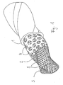
- the in Fig. 1 Stator shown has an outer tube 1 made of a solid material, for. As steel, in the interior of which the inner tubes 2 and 3 are located.
- the outer tube 1 closest inner tube 2 has openings 4.
- the inner tube 2 In the inner tube 2 is the inner tube 3.
- the lining 6 of the outer tube is in Fig. 1 not shown.
- the openings 4 of the inner tube 2 and the openings 5 of the inner tube 3 are in an advantageous embodiment of the invention of different sizes, in particular, the openings 4 are larger.
- the elastomer material of the lining surround the inner tube 3 through the openings 5, so that a particularly good adhesion between the lining 6 and the inner tube 3 and to the outer tube 1 is formed.
- the inner tube 3 is almost embedded in the elastomer composition. 6
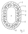
- Fig. 2 is a cross section of a stator shown as in Fig. 1 is shown.
- the inner tubes 2 and 3 which have the openings 4 and 5 in the outer tube 1.
- the lining 6 is shown in the outer tube 1.
- the lining 6 surrounds the bore 7, which is only roughly shown here.
- the bore 7 forms the space for receiving the material to be conveyed (pump cavity) if the stator is used in an eccentric screw pump, or the space for receiving the flowing drive means, if the stator is part of a used as a motor device.
- the bore 7 extends over the entire length of the stator. It is spiral-wound in two or more orbits and serves to receive a rotor, not shown here.
- the forces occurring during use of the pump are absorbed by the lining 6 and forwarded to the outer tube 1, via which the bearing of the pump takes place. For a firm connection between outer tube 1 and lining 2 must therefore be taken care of. This is done according to the invention by the inner tubes 2 and 3.
- the inner tubes 2 and 3 are arranged, which have a perforation or a plurality of openings 4 and 5 respectively.
- the openings 4 and 5 are filled by the material of the lining 6.
- a connection made by vulcanization or gluing between outer tube and lining can be omitted.
- the gluing or vulcanization is dispensed with.
- the bore 7 is helically wound.
- the outer tube 1 is shaped so that it runs parallel or nearly parallel to the outer contours of the cavity 7.
- a same, at least almost equal wall thickness of the lining 6 is achieved, which has proven to be advantageous in certain applications compared to stators with cylindrically shaped outer tubes.
- the inner tubes 2 and 3 can be formed by commercially available perforated plates, which are bent cylindrically. To produce a stator according to the invention, the inner tubes 2 and 3 are inserted into the outer tube 1 and all tubes 1, 2 and 3 are brought into the desired coiled shape. But it is also possible to first deform the tubes 1, 2 and 3 separately from each other, then put them together, such as by the inner tubes 2 and 3 are screwed into the outer tube 1. Subsequently, the rubber material of the lining 2 can be introduced by spraying.
- the inner tube 2 also from a hose made of elastomeric material or the like., In particular rubber exist.
- This hose not shown, is pushed over the inner tube 3.
- the inner tube 3 and the tube are then spent in the outer tube 1.
- the tube can also - as the inner tube 2 - have perforations, in which the elastomeric material of the liner 6 can flow.
- stator is made without a firmly adhering connection between the outer tube 1 and lining 2
- a mechanical, positive connection between the lining 2 and the inner tube 4 is formed, in contrast to stators with a chemical rubber-metal compound but can not be excluded be that it comes through a gap between the outer tube 1 and the liner 2 to a leakage and thus to a pressure drop between the suction side and pressure side of the pump. This can be prevented by a clamping seal at the front ends of the lining 2.
- Two embodiments of such a clamping gasket will be described below with reference to the Fig. 3 and 4 be explained.
- a conical sealing ring 10 is provided, which has a cylindrical portion 11, a conical portion 12 and a sealing bead 13.
- the conical portion 12 is spaced from the inside of the outer tube 1 and formed so that its distance from the outer tube 1 increases toward the interior of the stator.
- the sealing ring 10 is connected via a weld 14 to the outer tube 1.
- the sealing ring 10 may be connected by a press fit with the outer tube 1 instead of a welded joint.
- a clamping ring 15 is arranged on the sealing ring 10, which has a cylindrical portion 16, a conical portion 17 and a stop 18.
- the sealing ring 10 is introduced into the outer tube 1, positioned and possibly fixed there before the material (rubber) of the lining 2 is introduced into the outer tube 1.
- a conical annular gap 19 between the conical portion 12 of the sealing ring 10 and the outer tube 1 is filled with rubber.
- the rubber shrinks on cooling, however, both the outer tube 1 and the sealing ring 10 away.
- the clamping ring 15 is pressed axially.
- the wall thickness of the clamping ring 15 is greater in the conical portion 17 than the wall thickness of the conical portion 12 of the sealing ring 10. This ensures that the conical portion 17 of the clamping ring 15 presses the conical portion 12 of the sealing ring 10 to the outside.
- the sealing bead 13 of the sealing ring 10 prevents slipping out of the rubber from the annular gap 19 under conditions of use.
- a simple sealing ring 20 is provided in the embodiment according to Fig. 4 .
- This sealing ring 20 is suitable for installation after the introduction of the lining 2 in the outer tube.
- the liner 2 made of rubber or a similar material on the Injection process connected to the pipes 1 and 4.
- the end portion 21 of the lining 2 z. B. shaped as shown at 22 in dashed lines.
- the sealing ring 20 which is partially conical, is inserted into the outer tube 1.
- the end region 21 of the lining 2 is compressed by the conical region 24 of the sealing ring 20 and pressed firmly against the outer tube 1.
- the sealing ring 20 may, as shown at 23, connected by a weld with the outer tube 1 and secured against axial displacement. According to another embodiment of the invention, the sealing ring 20 may also be secured against displacement by a press fit between the sealing ring 20 and outer tube 20.
- Fig. 3 and 4 Possibilities for sealing the invention are shown. It is understood that these seals can be applied both in such stators, which z. B. have no coiled, but a cylindrical outer tube, as well as for coiled stators according to the Fig. 1 and 2 are suitable.
- the outer tube 1 may also have openings. It is not mandatory that the outer tube has a closed surface.
Landscapes
- Engineering & Computer Science (AREA)
- Mechanical Engineering (AREA)
- General Engineering & Computer Science (AREA)
- Rotary Pumps (AREA)
- Details And Applications Of Rotary Liquid Pumps (AREA)
- Structures Of Non-Positive Displacement Pumps (AREA)
Applications Claiming Priority (2)
| Application Number | Priority Date | Filing Date | Title |
|---|---|---|---|
| US10/714,812 US7131827B2 (en) | 2003-11-17 | 2003-11-17 | Stator for an eccentric screw pump or an eccentric worm motor operating on the moineau principle |
| EP04803164A EP1738078B1 (fr) | 2003-11-17 | 2004-11-17 | Stator pour pompe a vis sans fin excentrique ou moteur a vis sans fin excentrique selon le principe de moineau |
Related Parent Applications (1)
| Application Number | Title | Priority Date | Filing Date |
|---|---|---|---|
| EP04803164A Division EP1738078B1 (fr) | 2003-11-17 | 2004-11-17 | Stator pour pompe a vis sans fin excentrique ou moteur a vis sans fin excentrique selon le principe de moineau |
Publications (3)
| Publication Number | Publication Date |
|---|---|
| EP2028372A2 true EP2028372A2 (fr) | 2009-02-25 |
| EP2028372A3 EP2028372A3 (fr) | 2014-08-27 |
| EP2028372B1 EP2028372B1 (fr) | 2015-07-29 |
Family
ID=34574064
Family Applications (2)
| Application Number | Title | Priority Date | Filing Date |
|---|---|---|---|
| EP04803164A Expired - Lifetime EP1738078B1 (fr) | 2003-11-17 | 2004-11-17 | Stator pour pompe a vis sans fin excentrique ou moteur a vis sans fin excentrique selon le principe de moineau |
| EP08018529.1A Expired - Lifetime EP2028372B1 (fr) | 2003-11-17 | 2004-11-17 | Stator pour une pompe à vis sans fin excentrique ou un moteur à vis sans fin excentrique selon le principe Moineau |
Family Applications Before (1)
| Application Number | Title | Priority Date | Filing Date |
|---|---|---|---|
| EP04803164A Expired - Lifetime EP1738078B1 (fr) | 2003-11-17 | 2004-11-17 | Stator pour pompe a vis sans fin excentrique ou moteur a vis sans fin excentrique selon le principe de moineau |
Country Status (6)
| Country | Link |
|---|---|
| US (2) | US7131827B2 (fr) |
| EP (2) | EP1738078B1 (fr) |
| BR (1) | BRPI0416662B1 (fr) |
| CA (2) | CA2473001C (fr) |
| DE (1) | DE502004009512D1 (fr) |
| WO (1) | WO2005047702A2 (fr) |
Families Citing this family (19)
| Publication number | Priority date | Publication date | Assignee | Title |
|---|---|---|---|---|
| US7407372B2 (en) | 2004-05-14 | 2008-08-05 | Robbins & Myers Energy Systems L.P. | Progressing cavity pump or motor |
| GB2424452B (en) * | 2005-03-22 | 2011-01-19 | Schlumberger Holdings | Progressive cavity motor with rotor having an elastomer sleeve |
| RU2362880C1 (ru) * | 2007-12-27 | 2009-07-27 | Общество с ограниченной ответственностью "Фирма "Радиус-Сервис" | Статор винтовой героторной гидромашины |
| DE102008054961A1 (de) * | 2008-12-19 | 2010-07-01 | Endress + Hauser Flowtec Ag | Durchfluss-Messgerät und Verfahren zur Herstellung eines Messrohrs eines Durchfluss-Messgerätes |
| RU2402692C1 (ru) * | 2009-03-10 | 2010-10-27 | Открытое акционерное общество "Павловский машзавод" | Одновинтовая гидромашина |
| JP5364461B2 (ja) * | 2009-06-17 | 2013-12-11 | 宇明泰化工股▲ふん▼有限公司 | ポリテトラフルオロエチレン実撚糸及びその製造方法 |
| US8523545B2 (en) * | 2009-12-21 | 2013-09-03 | Baker Hughes Incorporated | Stator to housing lock in a progressing cavity pump |
| GB2481226A (en) * | 2010-06-16 | 2011-12-21 | Nat Oilwell Varco Lp | Stator for a progressive cavity (PC) pump or motor |
| CN102725530B (zh) * | 2010-08-25 | 2015-08-19 | 古河产机系统株式会社 | 单轴偏心螺杆泵中的定子密封结构 |
| US8672656B2 (en) | 2010-12-20 | 2014-03-18 | Robbins & Myers Energy Systems L.P. | Progressing cavity pump/motor |
| GB2499613B (en) | 2012-02-22 | 2017-11-01 | Nat Oilwell Varco Lp | Stator for progressive cavity pump/motor |
| DE102012112044B4 (de) * | 2012-05-04 | 2015-10-08 | Netzsch Pumpen & Systeme Gmbh | Selbstfixierendes Statorgehäuse |
| WO2015123288A2 (fr) | 2014-02-12 | 2015-08-20 | Roper Pump Company | Moteur hybride élastomère/métal sur métal |
| CN108050058B (zh) * | 2017-12-06 | 2019-06-25 | 中石化石油机械股份有限公司研究院 | 采油螺杆泵 |
| US11655815B2 (en) | 2019-12-13 | 2023-05-23 | Roper Pump Company, Llc | Semi-rigid stator |
| DE102020004334A1 (de) | 2020-07-20 | 2022-01-20 | Wilhelm Kächele GmbH | Stator für Exzenterschneckenmaschine |
| DE102021130260A1 (de) * | 2021-11-19 | 2023-05-25 | Wilhelm Kächele GmbH | Stator für Exenterschneckenmaschine sowie Herstellungsverfahren für diesen |
| US12018688B2 (en) | 2022-02-14 | 2024-06-25 | Johnson & Johnson Surgical Vision, Inc. | Sealing assembly for a progressive cavity pump |
| WO2023152594A1 (fr) * | 2022-02-14 | 2023-08-17 | Johnson & Johnson Surgical Vision, Inc. | Ensemble d'étanchéité pour une pompe à cavité progressive |
Family Cites Families (19)
| Publication number | Priority date | Publication date | Assignee | Title |
|---|---|---|---|---|
| US2700936A (en) * | 1951-10-05 | 1955-02-01 | Thompson Prod Inc | Flexible helix rotor pump |
| US2862454A (en) * | 1954-06-25 | 1958-12-02 | Robbins & Myers | Helical gear pumps |
| FR1414025A (fr) * | 1964-09-03 | 1965-10-15 | Loire Atel Forges | Perfectionnements aux machines à extruder |
| US3139035A (en) * | 1960-10-24 | 1964-06-30 | Walter J O'connor | Cavity pump mechanism |
| DE1553199C3 (de) * | 1966-03-15 | 1974-03-07 | Karl Dipl.-Ing. 7024 Bernhausen Schlecht | Nachstellbarer Stator für eine Exzenter-Schraubenpumpe |
| GB1211987A (en) * | 1968-04-29 | 1970-11-11 | Stenberg Flygt Ab | A screw pump provided with a radially movable rotor coupling |
| DE2250263C3 (de) * | 1972-10-13 | 1978-09-28 | Gummi-Jaeger Kg Gmbh & Cie, 3000 Hannover | Nachstellbarer Stator für Exzenterschneckenpumpen |
| DE2541779A1 (de) * | 1975-09-19 | 1977-03-31 | Allweiler Ag | Stator fuer exzenterschneckenpumpen |
| DE2713468C3 (de) * | 1977-03-26 | 1982-09-02 | Allweiler Ag, 7760 Radolfzell | Stator für Exzenterschneckenpumpen |
| JPS61180512A (ja) * | 1986-01-21 | 1986-08-13 | 日立電線株式会社 | 直接冷却型電力ケーブル線路の構成方法 |
| US5171139A (en) * | 1991-11-26 | 1992-12-15 | Smith International, Inc. | Moineau motor with conduits through the stator |
| DE4403598A1 (de) * | 1994-02-07 | 1995-08-10 | Arnold Jaeger | Exzenterschneckenpumpe |
| DE19804260C2 (de) * | 1998-02-04 | 2003-04-10 | Artemis Kautschuk Kunststoff | Elastomerstator für eine Exzenterschneckenpumpe |
| DE19827101A1 (de) * | 1998-06-18 | 1999-12-23 | Artemis Kautschuk Kunststoff | Nach dem Moineau-Prinzip arbeitende Maschine für den Einsatz in Tiefbohrungen |
| DE19842754C2 (de) | 1998-09-18 | 2001-04-26 | Seepex Seeberger Gmbh & Co | Exzenterschneckenpumpe |
| DE29822365U1 (de) * | 1998-12-16 | 1999-04-01 | Artemis Kautschuk- Kunststoff-Technik GmbH & Cie, 30559 Hannover | Elastomerstator für Exzenterschneckenpumpen |
| DE29909039U1 (de) * | 1999-05-22 | 1999-09-23 | J. Wagner Gmbh, 88048 Friedrichshafen | Förderpumpe mit Förderleitung |
| DE19950257B4 (de) * | 1999-10-18 | 2013-01-17 | Wilhelm Kächele GmbH Elastomertechnik | Exzenterschneckenpumpe mit vollausgekleidetem Stator |
| DE20013030U1 (de) * | 2000-07-20 | 2000-12-07 | Artemis Kautschuk- und Kunststofftechnik GmbH & Cie, 30559 Hannover | Verdrehsicherung für Statoren von Exzenterschneckenpumpen |
-
2003
- 2003-11-17 US US10/714,812 patent/US7131827B2/en not_active Expired - Lifetime
-
2004
- 2004-07-06 CA CA2473001A patent/CA2473001C/fr not_active Expired - Fee Related
- 2004-07-06 CA CA2712364A patent/CA2712364C/fr not_active Expired - Fee Related
- 2004-11-17 EP EP04803164A patent/EP1738078B1/fr not_active Expired - Lifetime
- 2004-11-17 WO PCT/EP2004/013037 patent/WO2005047702A2/fr not_active Ceased
- 2004-11-17 DE DE502004009512T patent/DE502004009512D1/de not_active Expired - Lifetime
- 2004-11-17 BR BRPI0416662A patent/BRPI0416662B1/pt not_active IP Right Cessation
- 2004-11-17 EP EP08018529.1A patent/EP2028372B1/fr not_active Expired - Lifetime
-
2006
- 2006-11-07 US US11/593,740 patent/US7329106B2/en not_active Expired - Fee Related
Also Published As
| Publication number | Publication date |
|---|---|
| WO2005047702A3 (fr) | 2005-11-24 |
| EP2028372A3 (fr) | 2014-08-27 |
| US7131827B2 (en) | 2006-11-07 |
| WO2005047702A2 (fr) | 2005-05-26 |
| US7329106B2 (en) | 2008-02-12 |
| EP1738078B1 (fr) | 2009-05-20 |
| EP1738078A2 (fr) | 2007-01-03 |
| DE502004009512D1 (de) | 2009-07-02 |
| BRPI0416662A (pt) | 2007-01-16 |
| BRPI0416662B1 (pt) | 2017-02-07 |
| US20050106052A1 (en) | 2005-05-19 |
| CA2712364A1 (fr) | 2005-05-17 |
| US20070053783A1 (en) | 2007-03-08 |
| CA2473001C (fr) | 2011-04-19 |
| CA2712364C (fr) | 2013-08-27 |
| CA2473001A1 (fr) | 2005-05-17 |
| EP2028372B1 (fr) | 2015-07-29 |
Similar Documents
| Publication | Publication Date | Title |
|---|---|---|
| EP2028372A2 (fr) | Stator pour une pompe à vis sans fin excentrique ou un moteur à vis sans fin excentrique selon le principe Moineau | |
| EP2994640B1 (fr) | Stator de pompe d'alimentation | |
| AT401417B (de) | Schiebehülsen-verbindung für kunststoffrohre | |
| EP2256345A2 (fr) | Stator pour une pompe à vis excentrique ou un moteur à vis excentrique et procédé de fabrication d'un stator | |
| DE19950257B4 (de) | Exzenterschneckenpumpe mit vollausgekleidetem Stator | |
| EP2640535B1 (fr) | Procédé et groupe d'éléments destinés à la fabrication d'un élément tubulaire, en particulier d'un arbre à cames assemblé | |
| EP2989282A2 (fr) | Tube métallique à raccord | |
| DE102005014128B4 (de) | Verbundschlauch und Verfahren zu seiner Herstellung | |
| EP1129292B1 (fr) | Vis pour une pompe a vis excentrique ou pour un moteur de forage souterrain | |
| DE10338632B4 (de) | Exzenterschneckenpumpe mit erosionsfestem Rotor | |
| EP1222396A1 (fr) | Stator avec anneau frontal rigide | |
| DE102005028818B3 (de) | Stator für eine Exzenterschneckenpumpe und Verfahren zu seiner Herstellung | |
| EP0824383B1 (fr) | Procede et outils de compression servant a relier des elements tubulaires | |
| EP2196716B1 (fr) | Couplage de tuyau | |
| DE202014103665U1 (de) | Stator einer Exzenterschneckenpumpe zum Fördern einer fließfähigen Fördermasse, insbesondere einer Baustoffmischung wie Mörtel | |
| DE19821807C2 (de) | Gebaute Aufweitlanze | |
| DE102019005367B4 (de) | Verfahren zur Herstellung eines Statorbauteil für eine Exzenterschneckenpumpe, Statorbauteil und Exzenterschneckenpumpe | |
| DE102017100540B4 (de) | Exzenterschneckenpumpe | |
| DE10049047C2 (de) | Verfahren zum Herstellen einer Nockenwelle und danach hergestellte Nockenwelle | |
| EP2730829A1 (fr) | Tuyau en plastique | |
| EP0119520B1 (fr) | Dispositif de raccordement pour un tuyau flexible | |
| DE102014116327A1 (de) | Verfahren zur Herstellung eines gewendelten Stators und Vorrichtung zur Herstellung eines gewendelten Stators | |
| DE102009008430A1 (de) | Exzenterschneckenpumpe, Stator dafür sowie Statormantelwandung und Verfahren zur Herstellung des Stators und der Statormantelwandung | |
| DE69912149T2 (de) | Verbindungsvorrichtung einer metallischen rohrleitung | |
| DE102019126675A1 (de) | Exzenterschneckenpumpe in modularer bauweise |
Legal Events
| Date | Code | Title | Description |
|---|---|---|---|
| PUAI | Public reference made under article 153(3) epc to a published international application that has entered the european phase |
Free format text: ORIGINAL CODE: 0009012 |
|
| AC | Divisional application: reference to earlier application |
Ref document number: 1738078 Country of ref document: EP Kind code of ref document: P |
|
| AK | Designated contracting states |
Kind code of ref document: A2 Designated state(s): DE FR GB |
|
| PUAL | Search report despatched |
Free format text: ORIGINAL CODE: 0009013 |
|
| PUAF | Information related to the publication of a search report (a3 document) modified or deleted |
Free format text: ORIGINAL CODE: 0009199SEPU |
|
| PUAL | Search report despatched |
Free format text: ORIGINAL CODE: 0009013 |
|
| PUAF | Information related to the publication of a search report (a3 document) modified or deleted |
Free format text: ORIGINAL CODE: 0009199SEPU |
|
| PUAL | Search report despatched |
Free format text: ORIGINAL CODE: 0009013 |
|
| AK | Designated contracting states |
Kind code of ref document: A3 Designated state(s): DE FR GB |
|
| RIC1 | Information provided on ipc code assigned before grant |
Ipc: F04C 2/107 20060101AFI20140624BHEP |
|
| D17D | Deferred search report published (deleted) | ||
| RIC1 | Information provided on ipc code assigned before grant |
Ipc: F04C 2/107 20060101AFI20140703BHEP |
|
| AK | Designated contracting states |
Kind code of ref document: A3 Designated state(s): DE FR GB |
|
| D17D | Deferred search report published (deleted) | ||
| AK | Designated contracting states |
Kind code of ref document: A3 Designated state(s): DE FR GB |
|
| RIC1 | Information provided on ipc code assigned before grant |
Ipc: F04C 2/107 20060101AFI20140718BHEP |
|
| RIC1 | Information provided on ipc code assigned before grant |
Ipc: F04C 2/107 20060101AFI20140804BHEP |
|
| 17P | Request for examination filed |
Effective date: 20150224 |
|
| RBV | Designated contracting states (corrected) |
Designated state(s): DE FR GB |
|
| GRAP | Despatch of communication of intention to grant a patent |
Free format text: ORIGINAL CODE: EPIDOSNIGR1 |
|
| AKX | Designation fees paid |
Designated state(s): DE FR GB |
|
| GRAS | Grant fee paid |
Free format text: ORIGINAL CODE: EPIDOSNIGR3 |
|
| INTG | Intention to grant announced |
Effective date: 20150428 |
|
| GRAA | (expected) grant |
Free format text: ORIGINAL CODE: 0009210 |
|
| AC | Divisional application: reference to earlier application |
Ref document number: 1738078 Country of ref document: EP Kind code of ref document: P |
|
| AK | Designated contracting states |
Kind code of ref document: B1 Designated state(s): DE FR GB |
|
| REG | Reference to a national code |
Ref country code: GB Ref legal event code: FG4D Free format text: NOT ENGLISH |
|
| REG | Reference to a national code |
Ref country code: DE Ref legal event code: R096 Ref document number: 502004014981 Country of ref document: DE |
|
| REG | Reference to a national code |
Ref country code: FR Ref legal event code: PLFP Year of fee payment: 12 |
|
| REG | Reference to a national code |
Ref country code: DE Ref legal event code: R097 Ref document number: 502004014981 Country of ref document: DE |
|
| PLBE | No opposition filed within time limit |
Free format text: ORIGINAL CODE: 0009261 |
|
| STAA | Information on the status of an ep patent application or granted ep patent |
Free format text: STATUS: NO OPPOSITION FILED WITHIN TIME LIMIT |
|
| 26N | No opposition filed |
Effective date: 20160502 |
|
| REG | Reference to a national code |
Ref country code: FR Ref legal event code: PLFP Year of fee payment: 13 |
|
| REG | Reference to a national code |
Ref country code: FR Ref legal event code: PLFP Year of fee payment: 14 |
|
| PGFP | Annual fee paid to national office [announced via postgrant information from national office to epo] |
Ref country code: FR Payment date: 20171124 Year of fee payment: 14 |
|
| PGFP | Annual fee paid to national office [announced via postgrant information from national office to epo] |
Ref country code: GB Payment date: 20171124 Year of fee payment: 14 |
|
| PGFP | Annual fee paid to national office [announced via postgrant information from national office to epo] |
Ref country code: DE Payment date: 20180116 Year of fee payment: 14 |
|
| REG | Reference to a national code |
Ref country code: DE Ref legal event code: R119 Ref document number: 502004014981 Country of ref document: DE |
|
| GBPC | Gb: european patent ceased through non-payment of renewal fee |
Effective date: 20181117 |
|
| PG25 | Lapsed in a contracting state [announced via postgrant information from national office to epo] |
Ref country code: FR Free format text: LAPSE BECAUSE OF NON-PAYMENT OF DUE FEES Effective date: 20181130 Ref country code: DE Free format text: LAPSE BECAUSE OF NON-PAYMENT OF DUE FEES Effective date: 20190601 |
|
| PG25 | Lapsed in a contracting state [announced via postgrant information from national office to epo] |
Ref country code: GB Free format text: LAPSE BECAUSE OF NON-PAYMENT OF DUE FEES Effective date: 20181117 |