EP1657781A1 - Appareil électronique avec une antenne - Google Patents
Appareil électronique avec une antenne Download PDFInfo
- Publication number
- EP1657781A1 EP1657781A1 EP20050256772 EP05256772A EP1657781A1 EP 1657781 A1 EP1657781 A1 EP 1657781A1 EP 20050256772 EP20050256772 EP 20050256772 EP 05256772 A EP05256772 A EP 05256772A EP 1657781 A1 EP1657781 A1 EP 1657781A1
- Authority
- EP
- European Patent Office
- Prior art keywords
- antenna
- radio wave
- coil
- coils
- antenna coil
- Prior art date
- Legal status (The legal status is an assumption and is not a legal conclusion. Google has not performed a legal analysis and makes no representation as to the accuracy of the status listed.)
- Granted
Links
- 229910052751 metal Inorganic materials 0.000 claims abstract description 16
- 239000002184 metal Substances 0.000 claims abstract description 16
- 230000035945 sensitivity Effects 0.000 abstract description 17
- 238000004804 winding Methods 0.000 description 13
- RYGMFSIKBFXOCR-UHFFFAOYSA-N Copper Chemical compound [Cu] RYGMFSIKBFXOCR-UHFFFAOYSA-N 0.000 description 10
- 239000011889 copper foil Substances 0.000 description 10
- 239000004020 conductor Substances 0.000 description 6
- 238000005476 soldering Methods 0.000 description 6
- 238000010586 diagram Methods 0.000 description 4
- 239000000463 material Substances 0.000 description 4
- 239000003990 capacitor Substances 0.000 description 2
- 239000000470 constituent Substances 0.000 description 2
- 230000000694 effects Effects 0.000 description 2
- 238000004519 manufacturing process Methods 0.000 description 2
- 230000000452 restraining effect Effects 0.000 description 2
- RTAQQCXQSZGOHL-UHFFFAOYSA-N Titanium Chemical compound [Ti] RTAQQCXQSZGOHL-UHFFFAOYSA-N 0.000 description 1
- 239000003795 chemical substances by application Substances 0.000 description 1
- 239000000284 extract Substances 0.000 description 1
- 239000004973 liquid crystal related substance Substances 0.000 description 1
- 229910001220 stainless steel Inorganic materials 0.000 description 1
- 239000010935 stainless steel Substances 0.000 description 1
- 239000010936 titanium Substances 0.000 description 1
- 229910052719 titanium Inorganic materials 0.000 description 1
Images
Classifications
-
- G—PHYSICS
- G04—HOROLOGY
- G04G—ELECTRONIC TIME-PIECES
- G04G21/00—Input or output devices integrated in time-pieces
- G04G21/04—Input or output devices integrated in time-pieces using radio waves
-
- G—PHYSICS
- G04—HOROLOGY
- G04R—RADIO-CONTROLLED TIME-PIECES
- G04R60/00—Constructional details
- G04R60/06—Antennas attached to or integrated in clock or watch bodies
- G04R60/10—Antennas attached to or integrated in clock or watch bodies inside cases
- G04R60/12—Antennas attached to or integrated in clock or watch bodies inside cases inside metal cases
-
- H—ELECTRICITY
- H01—ELECTRIC ELEMENTS
- H01Q—ANTENNAS, i.e. RADIO AERIALS
- H01Q1/00—Details of, or arrangements associated with, antennas
- H01Q1/27—Adaptation for use in or on movable bodies
- H01Q1/273—Adaptation for carrying or wearing by persons or animals
-
- H—ELECTRICITY
- H01—ELECTRIC ELEMENTS
- H01Q—ANTENNAS, i.e. RADIO AERIALS
- H01Q21/00—Antenna arrays or systems
- H01Q21/28—Combinations of substantially independent non-interacting antenna units or systems
-
- H—ELECTRICITY
- H01—ELECTRIC ELEMENTS
- H01Q—ANTENNAS, i.e. RADIO AERIALS
- H01Q7/00—Loop antennas with a substantially uniform current distribution around the loop and having a directional radiation pattern in a plane perpendicular to the plane of the loop
Definitions
- the present invention relates to an electronic apparatus having an antenna for receiving radio wave by an antenna coil.
- an antenna apparatus for receiving radio wave by winding an antenna coil around an antenna magnetic core member referred to as core.
- Patent Reference 1 in order to deal with frequencies or the like of a plurality of different long standard radio waves , there is disclosed an antenna having a plurality of coils at a core, changing inductances thereof by switching by a switch to thereby enable to change tuning frequencies.
- a receiving sensitivity of an antenna is influenced by a volume of a core and a coil volume
- a nonwinding portion for connecting antennas disposed at both ends of the core. Therefore, in order to provide a predetermined necessary coil volume, it is necessary to increase turn numbers of the respective coils by enlarging the core to pose a problem that a size thereof is enlarged.
- Patent References 1, 2, mentioned above disclose a radio wave timepiece having a plurality of tuning circuits
- the tuning circuits are for tuning to frequencies different from each other (for example, 40kHz and 60kHz) and are not for tuning to the same frequency.
- an electronic apparatus having an antenna having a plurality of antenna coils, characterized in that the plurality of antenna coils are constituted by being wound to laminate on a plurality of layers.
- the plurality of antenna coils wound to laminate on the plurality of layers are constituted by a first coil wound around a lower layer and a second coil wound around an upper layer of the first antenna coil and the inductance value of the first antenna coil is smaller than the inductance value of the second antenna coil.
- the first antenna coil when the first and the second antenna coils are contained in a plastic cabinet, the first antenna coil is used as the antenna and when the first and the second antenna coils are contained in a metal cabinet, the second antenna coil is used as the antenna.
- a constitution further comprising a timepiece movement wherein the antenna coils wound around the plurality of layers are constituted by being arranged in the timepiece movement so as not to be projected from a contour of the timepiece movement.
- terminals of the respective antenna coils are constituted by being electrically connected to a lead board.
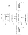
- Fig.1 is a block diagram of an electronic apparatus having an antenna according to the embodiment of the invention, showing an example of a radio wave timepiece for receiving a time code signal including information of current time by a radio wave signal and correcting time counted by counting means by the information of the current time included in the time code signal.
- the radio wave timepiece includes an antenna 101, a radio wave receiving IC (integrated circuit) 104 constituting a radio wave receiving portion, a control circuit 105 for controlling respective constituent elements of the radio wave timepiece, an operating member 106 of a winding crown or the like, a display mechanism 107 as displaying means for displaying time or the like based on a time signal from the control circuit 105, and a power source 108 for supplying a power to the respective constituent elements.
- IC integrated circuit
- the radio wave receiving IC 104 includes an AGC amplifying circuit for amplifying a signal received by the antenna 101, and a decoding circuit for extracting a time code signal representing current time from an output signal of the AGC amplifying circuit.
- the display mechanism 107 is constituted by time hands including an hour hand and a minute hand and these driving mechanism in the case of an analog display type radio wave timepiece and is constituted by a liquid crystal display apparatus or the like in the case of a digital display type radio wave timepiece.
- the antenna 101 includes a plurality of antenna coils (first antenna coil 103, second antenna coil 102) for receiving radio wave signals including time information (long standard radio wave signals in Japan).
- the antenna coils 102, 103 are respectively connected to capacitors, not illustrated.
- the antenna coils 102, 103 and the capacitors in correspondence therewith constitute tuning circuits tuning frequencies of which are the same as each other and having the tuning frequencies the same as a frequency of the radio wave signal (for example, 40kHz).
- the antenna coil 102 is the antenna coil having an inductance value larger than an inductance value of the antenna coil 103 and achieving an excellent receiving sensitivity by being used when a cabinet (outfit) for containing the antenna 101 comprises a metal (for example, stainless steel, titanium).
- the antenna coil 103 is the antenna coil having the inductance value smaller than the inductance value of the antenna coil 102 and achieving an excellent receiving sensitivity by being used when the cabinet containing the antenna 101 comprises plastic.
- antenna coil 102 and antenna coil 103 it is previously selected in fabrication to use one of the plurality of antenna coils (antenna coil 102 and antenna coil 103) in accordance with a kind of a material or the like of the cabinet.
- the radio wave receiving IC 104 extracts the time code signal including the information of the current time by decoding the radio wave signal received by the tuning circuit previously selected from a tuning circuit including the antenna coil 102 and a tuning circuit including the antenna coil 103 in accordance with the kind of the cabinet and outputs the time code signal to the control circuit 105.
- the control circuit 105 corrects current time counted by counting means provided at inside of the control circuit based on the time code signal to display at the display mechanism 107. Thereby, the correct current time is displayed at the display mechanism 107.
- the antenna coil having the pertinent characteristic is selected to be used in accordance with the kind of the cabinet for containing the antenna 101 and therefore, radio wave can excellently be received without being influenced by a material of the cabinet of the radio wave timepiece.
- a selector is provided at inside of the radio wave receiving IC 104 and is automatically switched to receive the signal of the antenna coil of either of the antenna coils 102, 103.
- the control circuit 105 controls the selector to switch the antenna coil receiving the radio wave to other antenna coil under a predetermined condition in which the correct time code signal cannot be received from the radio wave receiving IC 104 by the antenna coil currently used.
- the radio wave can excellently be received automatically by restraining the influence of the material of the cabinet containing the antenna 101 effected on the receiving sensitivity.
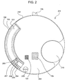
- Fig.2 is a front view showing an inner mechanism of the radio wave timepiece shown in Fig.1, and portions the same as those of Fig.1 are attached with the same notations.
- Fig.3 is a partially enlarged front view of the antenna used in the radio wave timepiece shown in Fig.1 and Fig. 2 and portions the same as those of Fig.1 and Fig. 2 are attached with the same notations.
- Fig.4 is a partially enlarged bottom view of the antenna used in the radio wave timepiece shown in Fig.1 and Fig. 2 and portions the same as those of Fig.1 through Fig. 3 are attached with the same notations.
- the radio wave timepiece includes a timepiece movement 201 having a contour in a shape of a circular disk.
- the timepiece movement 201 includes a frame 202 in a shape of a circular disk.
- a battery 210 constituting the power source 108, a circuit board 203, and the antenna 101 are contained at inside of the frame 202.
- the radio wave receiving IC 104, the control circuit 105 and the like are soldered to the circuit board 203.
- the antenna 101 is arranged at inside of the contour of the timepiece movement 201 so as not to be projected from the contour of the timepiece movement 201.
- the antenna 101 includes the plurality of antenna coils 102, 103 wound to laminate on a plurality of layers at a single common core 208.
- Inductance values of the plurality of antenna coils 102, 103 are constituted to differ from each other.
- the inductance value of the first antenna coil 103 wound around a lower layer is constituted to be smaller than the inductance value of the second antenna coil 102 wound around an upper layer.
- the antenna coil 102 is an antenna coil achieving an excellent receiving sensitivity when the antenna coil 102 is used in the case in which a cabinet containing the antenna 101 comprises a metal and the antenna coil 103 is an antenna coil achieving an excellent receiving sensitivity when the antenna coil 103 is used in the case in which the cabinet containing the antenna 101 comprises plastic.
- a winding of the antenna coil 103 wound around the lower layer is constituted by a winding of a conductor bolder than a winding of the antenna coil 102 formed around the upper layer.
- Terminals of the antenna coils 102, 103 are electrically connected to a lead board 204. That is, one end of the antenna coil 103 is electrically connected to a copper foil pattern 207 provided at the lead board 204 and other end thereof is electrically connected to a copper foil pattern 206. Further, one end of the antenna coil 102 is electrically connected to the copper foil pattern 206 and other end thereof is electrically connected to a copper foil pattern 205. Portions of connecting the respective terminals of the antenna coils 102, 103 and the lead board 204 are covered by a mold agent 401.
- one end of a conductor winding for the antenna coil 103 having a larger wire diameter is subjected to terminal processing of soldering or the like at the copper foil pattern 207, the conductor winding is wound around a core 208 by a predetermined number of times and thereafter, other end of the winding is subjected to terminal processing of soldering or the like at the copper foil pattern 206.
- a conductor winding for the antenna coil 102 having a wire diameter smaller than that of the conductor winding for the antenna coil 103 is subjected to terminal processing of soldering or the like at the copper foil pattern 206, the conductor winding is wound around an upper layer of the winding of the antenna coil 102 by a predetermined number of times and thereafter, other end of the winding is subjected to terminal processing of soldering or the like at the copper foil pattern 205.
- the lead board 204 and the circuit board 203 are integrally fixed to the frame 202 by a screw 209 via a through hole 301, thereby, the lead board 204 and the circuit board 203 are electrically connected.
- the copper foil patterns 205, 206 are electrically connected to the circuit board 203, and is subjected to a processing of soldering or the like to connect a tuning circuit including the antenna coil 102 to the radio wave receiving IC 104.
- the copper foil patterns 206, 207 are electrically connected to the circuit board 203 and is subjected to a processing of soldering or the like to connect a tuning circuit including the antenna coil 103 to the radio wave receiving IC 104.
- both of the antenna coils 102, 103 may electrically be connected to the radio wave receiving IC 104.
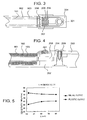
- Fig.5 is a characteristic diagram showing a relationship between an inductance L of a tuning circuit including an antenna coil and a sensitivity and is a graph constituted by respectives of a case of containing the tuning circuit in a plastic cabinet (outfit) and a case of containing the tuning circuit in a metal cabinet (outfit).
- the abscissa designates the inductance L (mH) of the antenna coil and the ordinate designates the sensitivity (dB ⁇ V/m) by a combination with a receiving circuit 10.
- a degree of a reduction in a sensitivity when the antenna coil is put into a metal cabinet is alleviated and therefore, the larger inductance constitutes a characteristic advantageous for the metal cabinet.
- a smaller inductance (antenna coil 103) constitutes a characteristic advantageous in view of the sensitivity.
- the optimum inductance value of the antenna coil differs between the case in which the cabinet of enclosing a radio wave timepiece module comprises plastic and the case in which the cabinet comprises a metal, as in the embodiment, by providing a plurality of antenna coils (tuning circuits) respectively optimized for the plastic cabinet and for the metal cabinet and switching to select to use the antenna coil having a pertinent characteristic in accordance with a kind of a cabinet in fabrication, or switching to automatically select the antenna coil having a suitable characteristic under a predetermined condition, regardless of the kind of the cabinet, the radio wave timepiece module having an excellent receiving sensitivity and having high general purpose performance can be realized.
- the plurality of antennas 102, 103 are wound to laminate on the plurality of layers on the core 208 and therefore, a space of arranging the coils can be reduced and the radio wave timepiece can be downsized.
- the structure in which the plurality of antenna coils are wound by a number of layers as described above there can be constructed a constitution of restraining an influence on the receiving sensitivity effected in accordance with the kind of the cabinet for containing the antenna and therefore, it is not necessary in the radio wave timepiece to prepare a plurality of kinds of movement in correspondence with an environment and a plurality of environments can be dealt with by using the same movement.
- the invention is applicable to various kinds of electronic apparatus having antennas starting from portable electronic apparatus having antennas of a portable radio wave timepiece, a portable telephone, PHS (personal handyphone system) and the like. Further, the invention is not limited to cases in which cabinets comprise a metal and plastic and applicable to electronic apparatus having antennas using cabinets of various materials. Further, in the case of a radio wave timepiece, the invention is applicable also to radio wave timepieces used not only in Japan but also in the countries having different frequencies of the United States of America or the like.
- an electronic apparatus having an antenna having a plurality of antenna coils can be downsized.
Landscapes
- Physics & Mathematics (AREA)
- General Physics & Mathematics (AREA)
- Electric Clocks (AREA)
- Electromechanical Clocks (AREA)
- Details Of Aerials (AREA)
- Support Of Aerials (AREA)
Applications Claiming Priority (1)
| Application Number | Priority Date | Filing Date | Title |
|---|---|---|---|
| JP2004327203A JP2006140659A (ja) | 2004-11-11 | 2004-11-11 | アンテナ付き電子機器 |
Publications (2)
| Publication Number | Publication Date |
|---|---|
| EP1657781A1 true EP1657781A1 (fr) | 2006-05-17 |
| EP1657781B1 EP1657781B1 (fr) | 2008-04-16 |
Family
ID=35798305
Family Applications (1)
| Application Number | Title | Priority Date | Filing Date |
|---|---|---|---|
| EP20050256772 Expired - Lifetime EP1657781B1 (fr) | 2004-11-11 | 2005-11-02 | Appareil électronique avec une antenne |
Country Status (5)
| Country | Link |
|---|---|
| US (1) | US7307594B2 (fr) |
| EP (1) | EP1657781B1 (fr) |
| JP (1) | JP2006140659A (fr) |
| CN (1) | CN1773397A (fr) |
| DE (1) | DE602005006073T2 (fr) |
Families Citing this family (6)
| Publication number | Priority date | Publication date | Assignee | Title |
|---|---|---|---|---|
| JP5029201B2 (ja) | 2007-08-08 | 2012-09-19 | セイコーエプソン株式会社 | 受信装置、電波時計および受信方法 |
| US7889083B2 (en) * | 2007-11-19 | 2011-02-15 | Round Rock Research, Llc | RFID device time synchronization from a public source |
| JP4821882B2 (ja) * | 2009-05-25 | 2011-11-24 | カシオ計算機株式会社 | 電子機器 |
| US8456368B2 (en) | 2009-01-27 | 2013-06-04 | Casio Computer Co., Ltd. | Antenna device and radio-wave receiver with such antenna device |
| US9124303B2 (en) * | 2011-10-19 | 2015-09-01 | Nokia Technologies Oy | Apparatus and method for near field communication |
| CN112363374B (zh) * | 2020-11-02 | 2022-05-17 | 东莞市迪尚智能生活科技有限公司 | 一种基于物联网的手表上弦系统以及方法 |
Citations (6)
| Publication number | Priority date | Publication date | Assignee | Title |
|---|---|---|---|---|
| EP0703513A1 (fr) * | 1994-04-08 | 1996-03-27 | Citizen Watch Co. Ltd. | Antenne pour appareil electronique portable |
| DE19607806A1 (de) * | 1995-03-07 | 1996-09-12 | Isa France Sa | Uhr, insbesondere in der Ausführung als Armbanduhr |
| WO1997043798A1 (fr) * | 1996-05-14 | 1997-11-20 | Casio Computer Co., Ltd. | Antenne, procede de fabrication associe et appareil electronique dote de celle-ci |
| JP2003043167A (ja) * | 2001-07-31 | 2003-02-13 | Mitsubishi Materials Corp | 腕時計用のアンテナ及びそれを内蔵する腕時計 |
| JP2003060520A (ja) | 2001-08-22 | 2003-02-28 | Casio Comput Co Ltd | 長波標準電波受信機 |
| EP1420477A1 (fr) * | 2002-11-13 | 2004-05-19 | Mitsubishi Materials Corporation | Montre avec étiquette IRF |
Family Cites Families (3)
| Publication number | Priority date | Publication date | Assignee | Title |
|---|---|---|---|---|
| DE8815967U1 (de) * | 1988-05-27 | 1989-09-21 | Junghans Uhren GmbH, 7230 Schramberg | Antenne für eine kleine Funkuhr |
| US7161551B2 (en) * | 2003-10-09 | 2007-01-09 | Casio Computer Co., Ltd. | Antenna and wristwatch |
| AU2006265193A1 (en) | 2005-07-01 | 2007-01-11 | Cinvention Ag | Process for the production of porous reticulated composite materials |
-
2004
- 2004-11-11 JP JP2004327203A patent/JP2006140659A/ja active Pending
-
2005
- 2005-11-02 EP EP20050256772 patent/EP1657781B1/fr not_active Expired - Lifetime
- 2005-11-02 DE DE200560006073 patent/DE602005006073T2/de not_active Expired - Lifetime
- 2005-11-03 US US11/267,774 patent/US7307594B2/en not_active Expired - Fee Related
- 2005-11-11 CN CNA2005101194749A patent/CN1773397A/zh active Pending
Patent Citations (7)
| Publication number | Priority date | Publication date | Assignee | Title |
|---|---|---|---|---|
| EP0703513A1 (fr) * | 1994-04-08 | 1996-03-27 | Citizen Watch Co. Ltd. | Antenne pour appareil electronique portable |
| JP3526874B2 (ja) | 1994-04-08 | 2004-05-17 | シチズン時計株式会社 | 携帯型電子機器のアンテナ装置 |
| DE19607806A1 (de) * | 1995-03-07 | 1996-09-12 | Isa France Sa | Uhr, insbesondere in der Ausführung als Armbanduhr |
| WO1997043798A1 (fr) * | 1996-05-14 | 1997-11-20 | Casio Computer Co., Ltd. | Antenne, procede de fabrication associe et appareil electronique dote de celle-ci |
| JP2003043167A (ja) * | 2001-07-31 | 2003-02-13 | Mitsubishi Materials Corp | 腕時計用のアンテナ及びそれを内蔵する腕時計 |
| JP2003060520A (ja) | 2001-08-22 | 2003-02-28 | Casio Comput Co Ltd | 長波標準電波受信機 |
| EP1420477A1 (fr) * | 2002-11-13 | 2004-05-19 | Mitsubishi Materials Corporation | Montre avec étiquette IRF |
Non-Patent Citations (1)
| Title |
|---|
| PATENT ABSTRACTS OF JAPAN vol. 2003, no. 06 3 June 2003 (2003-06-03) * |
Also Published As
| Publication number | Publication date |
|---|---|
| JP2006140659A (ja) | 2006-06-01 |
| US7307594B2 (en) | 2007-12-11 |
| DE602005006073T2 (de) | 2009-05-07 |
| CN1773397A (zh) | 2006-05-17 |
| US20060097951A1 (en) | 2006-05-11 |
| DE602005006073D1 (de) | 2008-05-29 |
| EP1657781B1 (fr) | 2008-04-16 |
Similar Documents
| Publication | Publication Date | Title |
|---|---|---|
| US7659858B2 (en) | Antenna and electronic device | |
| KR101176655B1 (ko) | 모바일 전자 장치 및 모바일 전자 장치용 안테나 시스템 | |
| KR100389149B1 (ko) | 시계용안테나구조체 | |
| JP2005062161A (ja) | アンテナ内蔵式電子時計 | |
| US7777680B2 (en) | Electronic apparatus and timepiece | |
| JPWO2004105240A1 (ja) | 同調装置及びそれを用いた電波修正時計 | |
| EP2202841A2 (fr) | Dispositif d'antenne, dispositif récepteur et montre radio contrôlée | |
| EP1657781B1 (fr) | Appareil électronique avec une antenne | |
| CN102832454B (zh) | 具备天线的电子设备及电波表 | |
| JP2010048605A (ja) | アンテナ内蔵式電子時計 | |
| JP3098430B2 (ja) | 携帯無線機用ヘリカルアンテナ | |
| EP2187476A1 (fr) | Dispositif d'antenne, dispositif de réception et horloge d'onde radio | |
| JP2010016492A (ja) | アンテナコイルおよびこれを備えた受信回路 | |
| JP4193783B2 (ja) | アンテナ装置 | |
| JP4570938B2 (ja) | 電波時計 | |
| JP2006140658A (ja) | アンテナ付き電子機器 | |
| JP2005077361A (ja) | アンテナ内蔵式電子時計 | |
| CN103124000B (zh) | 天线、电波接收设备以及天线的制造方法 | |
| US20250080058A1 (en) | High frequency module and communication apparatus | |
| JP2002168978A (ja) | 電波時計 | |
| JP2004200738A (ja) | アンテナ装置 | |
| JP4305205B2 (ja) | アンテナ装置 | |
| JP2013098603A (ja) | アンテナ構造体、電波受信機器及びアンテナ構造体の製造方法 | |
| JPS5853231A (ja) | 腕時計形ラジオ受信機 | |
| JP5803604B2 (ja) | アンテナ構造体、電波受信機器及びアンテナ構造体の製造方法 |
Legal Events
| Date | Code | Title | Description |
|---|---|---|---|
| PUAI | Public reference made under article 153(3) epc to a published international application that has entered the european phase |
Free format text: ORIGINAL CODE: 0009012 |
|
| AK | Designated contracting states |
Kind code of ref document: A1 Designated state(s): AT BE BG CH CY CZ DE DK EE ES FI FR GB GR HU IE IS IT LI LT LU LV MC NL PL PT RO SE SI SK TR |
|
| AX | Request for extension of the european patent |
Extension state: AL BA HR MK YU |
|
| 17P | Request for examination filed |
Effective date: 20061103 |
|
| AKX | Designation fees paid |
Designated state(s): DE GB |
|
| 17Q | First examination report despatched |
Effective date: 20070515 |
|
| GRAP | Despatch of communication of intention to grant a patent |
Free format text: ORIGINAL CODE: EPIDOSNIGR1 |
|
| GRAS | Grant fee paid |
Free format text: ORIGINAL CODE: EPIDOSNIGR3 |
|
| GRAA | (expected) grant |
Free format text: ORIGINAL CODE: 0009210 |
|
| AK | Designated contracting states |
Kind code of ref document: B1 Designated state(s): DE GB |
|
| REF | Corresponds to: |
Ref document number: 602005006073 Country of ref document: DE Date of ref document: 20080529 Kind code of ref document: P |
|
| PLBE | No opposition filed within time limit |
Free format text: ORIGINAL CODE: 0009261 |
|
| STAA | Information on the status of an ep patent application or granted ep patent |
Free format text: STATUS: NO OPPOSITION FILED WITHIN TIME LIMIT |
|
| 26N | No opposition filed |
Effective date: 20090119 |
|
| PGFP | Annual fee paid to national office [announced via postgrant information from national office to epo] |
Ref country code: DE Payment date: 20121031 Year of fee payment: 8 |
|
| PGFP | Annual fee paid to national office [announced via postgrant information from national office to epo] |
Ref country code: GB Payment date: 20121031 Year of fee payment: 8 |
|
| GBPC | Gb: european patent ceased through non-payment of renewal fee |
Effective date: 20131102 |
|
| REG | Reference to a national code |
Ref country code: DE Ref legal event code: R119 Ref document number: 602005006073 Country of ref document: DE Effective date: 20140603 |
|
| PG25 | Lapsed in a contracting state [announced via postgrant information from national office to epo] |
Ref country code: DE Free format text: LAPSE BECAUSE OF NON-PAYMENT OF DUE FEES Effective date: 20140603 |
|
| PG25 | Lapsed in a contracting state [announced via postgrant information from national office to epo] |
Ref country code: GB Free format text: LAPSE BECAUSE OF NON-PAYMENT OF DUE FEES Effective date: 20131102 |