EP1659066A2 - Dispositif utilisé dans un appareil pour attacher des étiquettes à ficelle - Google Patents
Dispositif utilisé dans un appareil pour attacher des étiquettes à ficelle Download PDFInfo
- Publication number
- EP1659066A2 EP1659066A2 EP05256979A EP05256979A EP1659066A2 EP 1659066 A2 EP1659066 A2 EP 1659066A2 EP 05256979 A EP05256979 A EP 05256979A EP 05256979 A EP05256979 A EP 05256979A EP 1659066 A2 EP1659066 A2 EP 1659066A2
- Authority
- EP
- European Patent Office
- Prior art keywords
- tag
- attaching
- side wall
- coupling means
- controlling means
- Prior art date
- Legal status (The legal status is an assumption and is not a legal conclusion. Google has not performed a legal analysis and makes no representation as to the accuracy of the status listed.)
- Withdrawn
Links
Images





Classifications
-
- B—PERFORMING OPERATIONS; TRANSPORTING
- B65—CONVEYING; PACKING; STORING; HANDLING THIN OR FILAMENTARY MATERIAL
- B65C—LABELLING OR TAGGING MACHINES, APPARATUS, OR PROCESSES
- B65C7/00—Affixing tags
-
- B—PERFORMING OPERATIONS; TRANSPORTING
- B65—CONVEYING; PACKING; STORING; HANDLING THIN OR FILAMENTARY MATERIAL
- B65C—LABELLING OR TAGGING MACHINES, APPARATUS, OR PROCESSES
- B65C7/00—Affixing tags
- B65C7/003—Affixing tags using paddle-shaped plastic pins
- B65C7/005—Portable tools
Definitions
- the present invention relates to a tag-attaching device for shooting a pin which can bind clothes, socks, or the like or which can attach tags such as brand labels, price tags, material description, instructions or the like to a good by inserting one end portion of the pin into the good.
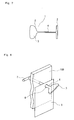
- FIG. 7 One embodiment of a specific configuration of a conventional tag-attaching pin is shown in Fig. 7.
- the tag-attaching pin 1 comprises a desired filament section 4, an insertion head section 2 provided at one end portion of the filament section 4 and a holding section 3 provided at the another end of the filament section 4 and which can hold a tag 5 thereon.
- the tag-attaching pin 1 is made of a suitable synthetic resin material and all of the above-mentioned sections are integrally molded into one body.
- the filament section 4 of the tag-attaching pin 1 is inserted into a hole 6 which had been previously provided on the tag 5 and then the insertion head section 2 of the tag-attaching pin 1 with the tag 5 held thereon, is penetrated through a desired portion of a desired good 100 so that the tag-attaching pin 1 is engaged with the good 100.
- a tag-attaching pin 10 as shown in Fig. 9, comprises a flexible filament section 12, an insertion head section 13 equipped with a suitable engagement section 16 located at one end of the filament section 12, and a socket section 15 equipped with a hole 14 for irreversibly passing the insertion head section 13 located at the other end of the filament section 12, wherein the hole 14 being provided with a pair of blade section 17, 17' inside thereof and which can engage with the engagement section 16 of the insertion head section 13.
- this conventional tag-attaching pin 1 and 10 is made of a synthetic resin material such as ordinal nylon resin, polyester resin or the like and also the insertion head section 13, the socket section or the holding section 15 and the filament section 12 thereof being integrally molded into one body.
- a desired good for example a bag 200
- a target good to which a tag should be attached
- the filament section 12 is inserted into a hole 410 previously provided on the tag 400, such as a label or the like
- the socket section 15 and a part of the filament section 12 are passed through a space formed between a gripping portion 300 of the bag and a surface of main body of the bag 200 and then the insertion head section 13 is inserted into the hole 14 formed inside the socket section 15 which having a function to hole the tag, so that a predetermined tag 400 can be attached to the good 200 with reducing the filament section 12 into a loop like configuration.
- a tag-attaching device 20 generally called a pin shooting gun
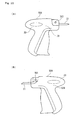
- the tag-attaching device 20 comprises a hollow needle 21 to be penetrated through a desired good so as to engage the insertion head section 2 of the tag-attaching pin 1 with a back side surface of the good and by operating a suitable lever 22, the insertion head section 2 is inserted into the hollow needle 21 and then the insertion head section 2 is pushed out from the hollow needle 21 utilizing a suitable pin pushing-out means so as to have the insertion head section 2 of the tag-attaching pin engaged with the good.
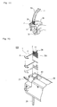
- the unit of tag-attaching pins 1 can be shot out from the tag-attaching device 20 one by one or it is also preferable that, as shown in Fig. 12, a plurality of the unit tag-attaching pins 1 are arranged in parallel with each other and they are simultaneously connected to a suitable connecting member such as a runner bar 24 via a respective suitable connecting member 11. As also shown in Fig. 12, the integrally assembled tag-attaching pins are inserted into an insertion portion 40 provided on a top end surface of the tag-attaching device 20 as shown in Fig. 11, so as to enable each one of the tag-attaching pins 1 to be successively shot individually into a predetermined good, so as to be attached to the good.
- an apparatus for attaching a tag-attaching pin which uses a sheet of tag-attaching pins as shown in Fig.13 in which a plurality of tag-attaching pins as shown in Fig. 9, are arranged in parallel configuration to each other and the parallel configuration thereof being kept fixedly by using a pair of connecting bars to which each one of the tag-attaching pin are connected to the connecting bar, respectively.
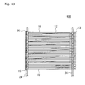
- tag-attaching pin 10 having such configuration as mentioned-above, it can also be used individually, but in many cases, in order to improve work efficiency, a plurality of loop pins 10 are arranged in a parallel configuration to form a sheet of tag-attaching pins 600 such as shown, for example, in Fig. 13.
- the structure of the loop pin sheet 600 is such that the individual loop pins 10 shown in Fig. 9 are provided so as to be mutually parallel and neighboring, and are caused to be connected to the connecting bars 24, 24' provided individually at or in the region of the plurality of insertion head portions 13 and at or in the vicinity of the plurality of socket portions 15, there further being a mutual linkage between the vicinity of the insertion head portions and the vicinity of the socket portions by means of the connection links 11, 11', as shown in Fig. 13.
- the above-noted sheet of tag-attaching pins 600 is normally formed integrally as one from, for example, synthetic resins such as nylon, polypropylene, or polyester or the like.
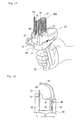
- the sheet of tag-attaching pins 600 can be mounted on an apparatus 20 for attaching a tag as shown in Fig. 14, and each time the operation lever 22 of the apparatus is activated, each one of the tag-attaching pins 10 is shot-out so as to attach a label or the like to a product.
- Fig 14 shows a condition in which the sheet of tag-attaching pins 600 is mounted on the apparatus 20 for attaching a tag-attaching pin in which the sheet of tag-attaching pins is bent so as to form an U-type configuration.
- Fig. 15 is an upper plan view of the apparatus for attaching a tag-attaching pin 20 as used in the conventional embodiment, in which a pair of vertical grooves 40, 41 are formed at a right had side portion and at a left hand side portion thereof into which connecting bars 24, 24' of the sheet of tag-attaching pins 600 are inserted, respectively.
- the connecting bar 24' linking the socket portions 15 of the sheet of tag-attaching pins 600 is inserted into the vertical groove 40, while the connecting bar 24 linking the insertion head portions 13 thereof is inserted into the vertical groove 41.
- the apparatus 20 for attaching a tag-attaching pin is provided with an out-pushing pin 42 at a position in the vicinity of the vertical groove 41 and which is driven by operation of the operation lever 22 as shown in Fig. 14, so as to cause a separation of the insertion head portion 13 from the connection link 11 of the connecting bar 24, thereby pushing out the same forward along the hollow tubular pin 21, one at a time.
- the socket portion 15 is pushed outward along the guide member 43 formed as a curved hollow guide member, by an appropriate out-pushing means, for example, by an out-pushing means 25 that is an out-pushing pin or a gear-rack system, so that it mates with the insertion head portion 13 that is pushed outward by the out-pushing pin 42 via a hollow guide formed by a hollow pin 21 at the front portion of the apparatus.
- an out-pushing means 25 that is an out-pushing pin or a gear-rack system
- the apparatus 20 for attaching a tag-attaching pin as shown in Fig. 16 although it uses the same mechanism as being substantially identical to that of the apparatus for attaching a tag-attaching pin 20 as shown in Fig. 14, and which also uses the sheet of tag-attaching pins 600 as shown in Fig. 13, in order to minimize the size of the apparatus for attaching a tag-attaching pin 20 and in effectively preventing a generation of jamming conditions in that a plurality of adjacently arranged tag-attaching pins are entangled with each other during the shooting operation for individual tag-attaching pins so that the problem causing the tag-attaching pin shooting operation impossible, specifically, the apparatus for attaching a tag-attaching pin 20 has a different configuration from those of other conventional embodiments.
- a part of a top upper surface of the apparatus 20, on which a vertical groove, that is an insertion slit 41 into which the connecting bar 24 to which a plurality of the inserting head sections 13 are connected, is inserted, is formed at a lower level in vertical direction comparing with the level of a part of the top surface of the apparatus 20, on which a vertical slit, that is an insertion slit 40 into which the connecting bar 24' to which a plurality of the socket sections 15 are connected, is inserted, is formed.
- a width of the apparatus 20 can be remarkably shortened so that a minimized apparatus 20 can be realized.
- Japanese Unexamined Patent Publication (KOKAI) No. 2000-85733 discloses the use of a guide member which can control an arranged locus configuration of a sheet of tag-attaching pins, and which is rotatably mounted on a top upper surface of the apparatus for attaching a tag-attaching pin.
- both an insertion portion of the sheet and a connecting bar are partially covered by a guide member so that the arranged locus configuration of the sheet is controlled, the insertion portion performs a sliding operation with the guide member and thus the arranged locus configuration of the insertion portion becomes different and accordingly, when one of the tag-attaching pin is shot out, a separate problem is arisen in that the tag-attaching pin cannot be shot out.
- the guide member is permanently fixed to the apparatus for attaching a tag-attaching pin and thus a separate problem is arisen in that an application of the apparatus is strictly limited.
- the invention seeks to provide for an attachment device having advantage over known such devices.
- the present invention seeks to resolve the above-mentioned problems as seen in the conventional technologies and to provide an attachment used for an apparatus for attaching a tag-attaching pin which eases the tag-attaching pin attaching operation especially when the apparatus is inserted into goods that are closely arranged to each other and a tag-attaching pin should be attached to a predetermined portion of each one of the goods.
- the invention can also seek to prevent a jamming condition caused by a plurality of tag-attaching pins or a sheet of tag-attaching pins being entangled with each other inside the apparatus, from being generated and to provide an apparatus for attaching a tag-attaching pin provided with the attachment.
- an attachment which can be used for an apparatus using a sheet of tag-attaching pins in which a plurality of tag-attaching pins, each comprising a filament section, an inserting head section provided at one end of the filament section, and a socket section or holding section provided at the another end of the filament section, are mutually arranged in parallel configuration and at least the inserting head section or a portion in the vicinity of the inserting head section and at least the socket section or holding section or a portion in the vicinity of the socket section or holding section of each one of the tag-attaching pins thereof, being connected to connecting bars so that the parallel configuration of the sheet of tag-attaching pins can be maintained, wherein the tag is attached to a desired good with the holding section by inserting the inserting head section of the tag-attaching pin into a hollow needle provided on the tag-attaching device and by penetrating the inserting head section through the good with pushing the inserting head section out of the hollow needle utilizing a predetermined pin pushing means, so as
- the attachment of the present invention can make a tag-attaching pin attaching operation utilizing the apparatus for attaching a tag-attaching pin easy and can significantly improve working efficiency.
- the apparatus is inserted into a plurality of goods, each being closely arranged to each other, and with the tag attached to a predetermined portion of each one of the goods utilizing the tag-attaching pin, since the attachment fixes and covers the sheet, when the apparatus is inserted into the predetermined group of goods so as to attach the tag-attaching pin to the good, the sheet is prevented from being hooked on the good and thus an interruption of the tag-attaching pin attaching operation is also effectively prevented from being generated.
- the operation to do so is not interrupted and the sheet is also prevented from being dropped out from the apparatus.
- the attachment is so configured that it is detachably mounted on the apparatus for attaching a tag-attaching pin and thus in accordance with a shape or arranged configuration of an objected good to which an tag-attaching pin should be attached, the present invention has an effect in that the apparatus for attaching a tag-attaching pin can be used without the attachment and accordingly, an application area for the apparatus is enlarged.
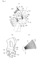
- FIG. 1 shows a construction of one embodiment of the attachment which can be detachably connected to an apparatus for attaching a tag-attaching pin as used in the present invention.
- Fig. 1 shows an attachment 500 of the present invention, which can be used for an apparatus 20 using a sheet of tag-attaching pins 600 in which a plurality of tag-attaching pins 1 or 10, each comprising a filament section 4 or 12, an inserting head section 2 or 13 provided at one end of the filament section 4 or 12, and a socket section 15 or a holding section 3 provided at the another end of the filament section, are mutually arranged in parallel configuration and at least the inserting head section 2 or 13, or a portion in the vicinity of the inserting head section 2 or 13 or at least the socket section 15 or the holding section 3 or a portion in the vicinity of the socket section 15 or the holding section 3 of each one of the tag-attaching pins 1 or 10 thereof, being connected to connecting bars 24 so that the parallel configuration of the sheet of tag-attaching pins 600 can be maintained.
- a plurality of tag-attaching pins 1 or 10 each comprising a filament section 4 or 12, an inserting head section 2 or 13 provided at one end of the filament section 4 or 12, and a
- the tag-attaching pin 1 or 10 is attached to a desired good 100 with the holding section 3 by inserting the inserting head section 2 of the tag-attaching pin 1 or 10 into a hollow needle 21 provided on the tag-attaching device 20 and by penetrating the inserting head section 2 or 13 through the good 200 with pushing the inserting head section 2 or 13 out of the hollow needle 21 utilizing a predetermined pin pushing means, so as to have the inserting head section 2 or 13 attached to a surface of the good 200 with the tag-attaching pin 1 or to have the inserting section 2 or 13 engaged with the socket section 15 of the tag-attaching pin 12 with the tag 400 via a part of the good 300 so that a tag 5 is kept by the filament section 4 or 12, wherein the attachment 500 is provided with a connecting portion 503 which can be detachably coupled with a coupling means 502 formed on a side wall surface of the apparatus 20 for attaching a tag-attaching pin.
- a tag-attaching pin controlling means 505 is provided on the side wall surface 501 of the an apparatus for attaching a tag-attaching pin 20 and extending upwardly from a top surface 504 of the apparatus for attaching a tag-attaching pin 20, the coupling means 502 and the tag-attaching pin controlling means 505 being integrally formed with each other, and further wherein a connecting bar controlling means 507 which can control an arranged locus configuration 506 of the connecting bars 24 of the sheet of the tag-attaching pins 600 is formed on at least a portion of the tag-attaching pin controlling means 505.
- the attachment 500 of the present invention is provided with a connecting portion 503 which can be detachably connected to the apparatus 20 for attaching a tag-attaching pin via a coupling means 502 provided on a surface of a side wall surface 501 of the apparatus 20 and a tag-attaching pin controlling means 505 which is provided on the side wall surface 501 of the an apparatus 20 which is integrally formed with the connecting portion 503 and extending upwardly from an upper top surface 504 and the side surface 501 of the apparatus 20 so as to form a wall like configuration.
- the tag-attaching pin controlling means 505 which forms the attachment 500 of the present invention, is also provided with a connecting bar controlling means 507 which serves to fix an arranged locus configuration 506 of the connecting bars 24 of the sheet of the tag-attaching pins 600 into a prescribed constant shape by engaging with the connecting bar 24 which is a part of the a sheet of tag-attaching pins 600.
- the connecting bar controlling means 507 may be provided at a relatively upper side portion of the tag-attaching pin controlling means 505, for example.
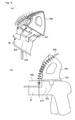
- the connecting bar controlling means 507 can comprise a guide wall portion (a first guide wall portion) 508 for forming an arranged locus configuration of the connecting bar 24 having a predetermined height and arranged along an outer edge portion 512 of a base plate 511 of the tag-attaching pin controlling means 505 and a connecting bar locus configuration holding means 509 which is provided on a part of a free end edge portion 513 of the guide wall portion 508 and formed in parallel with a surface of the base plate 511.
- the height of the guide wall portion 508 is not specifically restricted to a predetermined value though it can be designed, for example, to have a desired height taking into account of a length of a connecting portion 11 which is connecting the inserting head section 2 or 13 to the connecting bar 24 in the sheet of tag-attaching pins 600 or a length of a connecting portion 11 which is connecting the holding section 3 or the socket section 15 to the connecting bar 24 in the a sheet of tag-attaching pins 600.
- an auxiliary guide wall portion (a second guide wall portion) 510 which can keep the locus configuration of the connecting bars 24 at a prescribed shape, is provided.
- the tag-attaching pin controlling means 507 of the tag-attaching pin controlling means 505 can be formed at least a part of the outer peripheral edge portion 512 of the tag-attaching pin controlling means 505 and facing to a direction directing to a front end portion of the apparatus 20 and more specifically, the tag-attaching pin controlling means 507 comprises a first guide wall portion 508 for guiding the connecting bar 24 to form a predetermined locus configuration and a connecting bar locus configuration holding means 509.
- tag-attaching pin controlling means 505 of the present invention as shown in Fig. 2, it is a preferable embodiment of the present invention in that in an inside portion of the first guide wall portion 508, a second guiding wall portion 510 is provided on a surface of the tag-attaching pin controlling means 507 which is the same surface on which the connecting bar controlling means 505 is provided and wherein the a second guiding wall portion 510 can be contacted with a surface of the connecting bar 24, the surface thereof being opposite to a surface thereof to which the first guiding wall portion 508 is contacted.
- the attachment 500 of the present invention since it adopts the above-mentioned technical features, when the a sheet of tag-attaching pins 600 is mounted on an apparatus 20 for attaching a tag-attaching pin, a part of the connecting bar 24 forming the sheet of tag-attaching pins 600 is forced to be arranged along a guiding groove 540 which is formed with the first and the second guiding walls 508 and 510 and thus the arranged locus configuration thereof is fixedly kept as it is and accordingly, the problems in that the sheet 600 is swung or is dropped out from the apparatus during an operation can be effectively prevented.
- the arranged locus configuration O formed by the connecting bar 24 which is one of the elements of the a sheet of tag-attaching pins 600 utilizing the attachment 500 of the present invention, is preferably configured so that an angle ⁇ formed between the arranged locus configuration formed by the connecting bar 24 of the a sheet 600 created by the attachment 500 and a normal line P with respect to a top upper surface 504 of the attachment 500 is set at within 5 to 45 degrees.
- a configuration of a portion of the peripheral edge portion of the tag-attaching pin controlling means 505 and which is a portion close to a front end portion of the apparatus 20 is preferably formed to have a configuration which is curved directing to a rear portion of the tag-attaching pin controlling means 505 so that the predetermined angle ⁇ can be obtained.
- the angle ⁇ is set at an angle exceeding the upper limit thereof, for example, and when a sheet of tag-attaching pins 600 as shown in Fig. 12, is used, a plurality of adjacently arranged holding sections 3 provided on each one of the tag-attaching pin 1 are strongly contacted with each other and therefore entanglement frequently occurs among the adjacently arranged holding sections 3 causing failure of the tag-attaching pin shooting operation.
- the attachment 500 of the present invention comprises the tag-attaching pin controlling means 505 and the connecting portion 503 each being integrally formed with each other and made of plastic material or metallic material or a composite material comprising the above-mentioned materials.
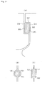
- a coupling means reception portion 514 which can be fixedly coupled with the coupling means (a first coupling means) 502 provided at least one of the side wall surfaces 501 of the apparatus 20 for attaching a tag-attaching pin and easily removed from the coupling condition formed therebetween.
- the first coupling means 502 of the present invention is formed by a projecting portion or a recessed portion having a suitable height or a depth formed integrally with a surface of the first side wall surface 501 of the apparatus 20, and the plane configuration thereof is preferably either one of a rectangular shape, a circular shape, a polygonal shape, an oval shape or the like.
- the coupling means reception portion 514 which can be detachably coupled with the first coupling means 502 preferably has a plane configuration being substantially identical to that of the first coupling means 502.
- the coupling means reception portion 514 preferably has an opening having a plane shape comprising a combination of a plurality of inner peripheral edge portions 517, 518 each individually contacting to at least a part of the outer peripheral edge portions 515, 516 of the coupling means 502, respectively.
- At least a part of the inner peripheral edge portions 517, 518 of the coupling means reception portion 514 which can be coupled with the first of connecting portion 502 preferably is preferably configured so that it can be easily displaced independently to change it position with respect to another inner peripheral edge portion in order to easily attach to or remove from the first coupling means 502.
- the second inner peripheral edge portions 518 is configured so that it can easily move to be displaced from its original position with respect to the first inner peripheral edge portions 517.
- the second inner peripheral edge portions 518 is configured so that it can easily change its position upwardly with respect to the first inner peripheral edge portions 517 in an upper direction of a surface of the paper of this Fig. 3.
- the connecting portion 503 comprises a first connecting portion 523 and a second connecting portion 524 each being separated from each other with a first slit portion 520 interposed therebetween and the coupling means reception portion 514 is preferably provided on a part of the first slit portion 520.
- the present invention can comprise a mechanism in which the first connecting portion 523 is configured to be movable to easily displace its position.
- the first connecting portion 523 is provided with a second slit portion 521 having, for example, a U-shaped or a V-shaped configuration and with this construction, the first connecting portion 523 can be easily moved upwardly and displaced with respect to the second connecting portion 524.
- a space portion 522 is provided at a portion formed between a part of an external peripheral edge portion of the first connecting portion 523 in which the second slit portion 512 is provided and the side wall surface of the apparatus 20 for attaching a tag-attaching pin and the space portion 522 being formed by moving a part of the outer peripheral edge portion of the first connecting portion 523 upwardly.
- the first connecting portion 523 can be easily lifted up so that the engagement formed between the apparatus for attaching a tag-attaching pin and the attachment 500 can be easily disengaged.
- the configuration of the coupling means reception portion 514 makes it possible that the apparatus for attaching a tag-attaching pin 20 and the attachment 500 to be easily engaged with each other.
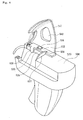
- the attachment 500 of the present invention is preferably provided with an auxiliary supporting mechanism. Additionally, this feature is provided since it is difficult to fixedly support the attachment 500 to a surface of a side wall of the apparatus 20 for attaching a tag-attaching pin effectively only with the above-mentioned connecting portion 503.
- a first supporting member 525 which can engage with a top upper surface 504 of the apparatus 20 and a first side wall surface 501 of the apparatus 20
- a second supporting member 528 which can engage with a top upper surface 504 of the apparatus 20 and a second side wall surface 529 provided on an opposite side of the first side wall surface 501 thereof or an inside side wall surface 526 of the second side wall surface 501.
- a projecting portion (a second coupling means reception portion) 531 which can be engaged with a recessed portion (a second coupling means) 530 which is provided on the first side wall surface 501 of the apparatus 20, is provided.
- connecting portion 503 and the tag-attaching pin controlling means 505 are integrally formed into one piece. Further an auxiliary supporting member 532 is preferably provided along a border line 533 formed between the connecting portion 503 and the tag-attaching pin controlling means 505 or a line formed in the vicinity of this border line 505.
- a length of the second supporting member 528 is greater relatively than that as mentioned in the separate embodiment since the second supporting member 528 is elongated so as to reach to a side wall surface (a second side wall surface) 529 which is an opposite side wall surface 501 of the apparatus 20.
- the second supporting member 528 is so configured so that it can be engaged with a step like portion formed by an inside side wall surface 526 of the second side wall surface 529 which is an opposite side wall surface to the surface of the apparatus 20 on which the attachment 500 of the present invention is attached.
- a attaching mechanism which having a substantially identical to that as shown in Fig. 4, can be provided on a first side wall surface formed in the vicinity of a portion on which a slit 40 for inserting the connecting bar thereinto is provided or on a second side wall surface formed opposite to the first side wall surface and formed in the vicinity of a portion on which a slit 41 for inserting the connecting bar thereinto is provided.
- auxiliary supporting member 532 is configured so that it can be detachably contacted tightly to a top upper surface 504 of the apparatus 20.
- the second supporting member 528 is connected to a part of a free end portion of the auxiliary supporting member 532.
- a projecting portion or a recessed portion 534 having a prescribed configuration is provided on a portion of a top end surface 504 of the apparatus 20 and an opening or a projecting portion 535 which can be coupled with the projecting portion or the recessed portion 534 previously provided on the top end surface 504 of the apparatus 20, is provided on the auxiliary supporting member 532.
- a third slit portion 536 which can be engaged with a suitable plate-like projecting portion 537 which is provided on a part of the apparatus 20.
- a recessed portion 541 is provided on a portion of a part of the external peripheral edge portion 512 of the tag-attaching pin controlling means 505 and the portion being formed in a direction to a front end portion of the apparatus 20 as well as on the portion formed at a position in the vicinity of the top upper end surface 504 of the apparatus 20.
- the recessed portion 541 eases the inserting operation for an operator the inserting operation of which is such that when the operator of the apparatus 20 seeks to mount a sheet of tag-attaching pins 600 on the apparatus 20 for attaching a tag-attaching pin, he or she should pick up the connecting bar 24 of the sheet 600 with his or her finger and try to insert an end portion of the connecting bar 24 into the slit 40 or 41.
- an aperture 542 is provided.
- this aperture 542 is an effective means to reduce a weight of the tag-attaching pin controlling means 505.
- one of the separate embodiments of the present invention is an attachment 500 which has a construction being different from that of the attachment 500 as shown in Figs. 1 to 5.
- the connecting portion 503 comprises the first and the second connecting portions and both connecting portions are so configured that each thereof being able to individually displace from each other.
- the attachment 500 has the technical feature such that on a portion of the connecting portion 503 located in the vicinity of a front end portion of the apparatus 20 for attaching a tag-attaching pin, there is provided a first supporting member 525 which can engage with a top upper surface 504 of the apparatus 20 and a side wall surface (a first side wall surface) 501 of the apparatus 20, and a second supporting member 528 which can engage with a top upper surface 504 of the apparatus 20 and a second side wall surface 529 provided on an opposite side of the first side wall surface 501 thereof or an inside side wall surface 526 of the second side wall surface 529, and further wherein on a portion of a surface of the connecting portion 503 and which is facing to, and contacted to, the first side wall surface 501 of the apparatus 20, there is provided with a first coupling means reception portion 601 which can be engaged with the first coupling means 502 provided on the first side wall surface 501 of the apparatus 20 and on a portion of a surface of the first
- the connecting portion 503 is integrally formed into one piece and since the connecting portion 503 is attached to the apparatus 20 for attaching a tag-attaching pin, the first coupling means 502 provided on the first side wall surface 501 of the apparatus 20 is arranged on a position a slightly lower position of a main body of the apparatus 20 comparing with the previous embodiment and further an arranging position of the first coupling means reception portion 601 which can be engaged with the first coupling means 502 in the connecting portion 503, is arranged at a position existing in the vicinity of a lower portion of the connecting portion 503.
- a picking-up portion or tab 604 is provided between the first side wall surface 501 of the apparatus and a portion of an external peripheral edge portion 609 of the connecting portion 503 and which is located in the vicinity of the first coupling means reception portion 601.
- a suitable slit portion 603 can be preferably provided.
- a third coupling means reception portion 606 which can be engaged with a third coupling means 605 provided on the second side wall surface of the apparatus 20 on a portion of a surface of the second supporting member 528 and which is facing to, and contacted to, the second side wall surface 526 or 529 of the apparatus 20.
- the third coupling means reception portion 606 which is provided on the second supporting member 528, is provided optionally and, as required, the second supporting member 528 is configured so as to have a bias force which can press at the second side wall surface 526 or 529.
- the second supporting member 528 can be formed to have a configuration in which a tip end portion of the second supporting member 528 is slightly inclined to a direction facing towards the second side wall surface 526 or 529, when it is molded.
- At least one of the first to third supporting members 502, 530 or 605 preferably comprises a portion selected from a group of portions comprising a projecting portion, a recessed portion and a hole portion provided on either one of the side wall surfaces 501, 526 or 529 of the apparatus 20.
- At least one of the first to the third coupling means reception portions 601, 531 or 606 comprises a portion selected from a group of portions comprising a projecting portion, a recessed portion and a hole portion each having a desired shape which can be coupled with either one of the projecting portion, the recessed portion and the hole portion each forming the first to the third coupling means, respectively.
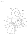
- the attachment 500 of the present invention to the apparatus 20 for attaching a tag-attaching pin, for example, firstly, after the projecting portion 531 forming the second coupling means reception portion and provided inside portion of the first supporting member 525 of the attachment 500, is inserted into a hole portion 530 forming the second coupling means provided on a front end portion of the apparatus 20 so as to couple them with each other by rotating the main body of the attachment 500 in a counter clock wise direction as shown in Fig. 1, the connecting portion 503 is abutted to the first side wall surface 501 of the apparatus 20 and slid downwardly. At the same time the second supporting member 528 is also abutted to the second side wall surface 529 or 526 and slid downwardly.
- the attachment 500 can be surely connected to the apparatus 20.
- the attachment 500 when the attachment 500 is removed from the apparatus for attaching a tag-attaching pin 20, at first, an operator inserts his or her finger or the like into the space portion formed between the connecting portion 503 and a surface formed by the first side wall surface 501 of the apparatus 20 so as to lift the picking up means 604 or tab provided at a lower portion of the connecting portion 503 and thereby the first coupling means reception portion 601 is removed from the first coupling means 502.
- the connecting portion 503 After the engagement formed between the first coupling means reception portion 601 and the first coupling means 502 has been released, by rotating the connecting portion 503 in a clockwise direction, the connecting portion 503 is removed from the side wall surface of the apparatus 20 and accordingly, the attachment 500 can be detached from the apparatus 20.
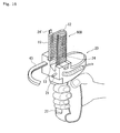
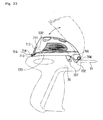
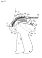
- an attachment 700 of this embodiment relates to a different attachment which can be used for an apparatus 20 for attaching a tag-attaching pin utilizing a sheet of tag-attaching pins 600 as shown in Figs. 5, 11 or 12, especially as shown in Figs 7 and 8.
- an attachment 700 of this embodiment can be used for an apparatus 20 using a sheet of tag-attaching pins in which a plurality of tag-attaching pins 1, each comprising a filament section 4, an inserting head section 2 provided at one end of the filament section 4, and a holding section 3 provided at the another end of the filament section, 4 are mutually arranged in parallel configuration and at least the inserting head section 2 or a portion in the vicinity of the inserting head section 2 is connected to a connecting bar 24 so that the parallel configuration of the sheet of tag-attaching pins 701 can be maintained.
- a plurality of tag-attaching pins 1, each comprising a filament section 4, an inserting head section 2 provided at one end of the filament section 4, and a holding section 3 provided at the another end of the filament section, 4 are mutually arranged in parallel configuration and at least the inserting head section 2 or a portion in the vicinity of the inserting head section 2 is connected to a connecting bar 24 so that the parallel configuration of the sheet of tag-attaching pins 701 can be maintained.
- the tag 5 is attached to a desired good 100 with the holding section 3 by inserting the inserting head section 2 of the tag-attaching pin 1 into a hollow needle 21 provided on the apparatus for attaching a tag-attaching pin 20 and by penetrating the inserting head section 2 through the good 100 with pushing the inserting head section 2 out of the hollow needle 21 utilizing a predetermined pin pushing means, so as to have the inserting section 2 attached to a surface of the good 100 with the tag 5.
- the attachment 700 is also provided with a tag-attaching pin controlling means 710 which can be attached to and mounted on a top upper surface 504 of the apparatus 20 for attaching a tag-attaching pin, a first supporting member 702 which is integrally formed with the tag-attaching pin controlling means 710 into one piece and which being provided with a first coupling means reception portion 704 being able to detachably couple with a first coupling means 703 formed on one side wall surfaces 501 of the apparatus 20, and a second supporting member 707 provided with a second coupling means reception portion 706 being able to detachably couple with a second coupling means 705 formed on another side wall surface 529 of the apparatus 20.
- a tag-attaching pin controlling means 710 which can be attached to and mounted on a top upper surface 504 of the apparatus 20 for attaching a tag-attaching pin
- a first supporting member 702 which is integrally formed with the tag-attaching pin controlling means 710 into one piece and which being provided with a first coupling means reception portion 70
- the tag-attaching pin controlling means 710 and the first and the second supporting members 702 and 707 are integrally formed into one piece, and a connecting bar controlling means 507, which can control an arranged locus configuration of the connecting bars 24 of the sheet of the tag-attaching pins 701, is formed on at least a portion of the tag-attaching pin controlling means 710.
- an attaching/detaching operation supporting member 712 for supporting an operation to attach or detach the tag-attaching pin controlling means 710 to or from the apparatus 20, is preferably provided at a rear portion 711 of the tag-attaching pin controlling means 710.
- the attaching/detaching operation supporting member 712 is provided with a movable member 715 to cause a spring effect at a part thereof and a third coupling means 713 formed at a free end portion of the attaching/detaching operation supporting member 712 and which can be coupled with a suitable coupling means reception portion 716 formed on a top upper surface 504 of the apparatus 20.
- the attaching/detaching operation supporting member 712 is preferably provided at a rear end portion 711 of the tag-attaching pin controlling means 710 by being integrally formed into one piece with the tag-attaching pin controlling means 710 via a slit portion 717 and it is also preferable that a tip end portion of the slit portion 717 is configured so that it is applied with a bias force in a direction of the tip end portion of the slit portion 717 being removed from a surface of the rear end portion 711 of the tag-attaching pin controlling means 710.
- the third coupling means 713 provided at the tip end portion of the attaching/detaching operation supporting member 712 can be inserted into the third coupling means reception portion 716 comprising a suitable recessed portion which is provided on a suitable position of the top upper surface 504 of the apparatus 20 thereby the attachment 700 can be fixedly connected to the top upper surface 504 of the apparatus 20.
- the attachment 700 of this embodiment is provided with a first supporting member 702 and a second supporting member 707 which is detachably connected to the apparatus 20 via a first coupling means 703 and a second coupling means 705 each having a suitable shape and provided on the side wall surfaces 501 of the apparatus 20, and further also is provided with a tag-attaching pin controlling means 710 which is integrally formed with a connecting portion into one piece and the connecting portion being projected and extended upwardly from the side wall surface 501 of the apparatus 20 and exceeding the top upper surface 504 of the apparatus so as to form a wall-like configuration.
- the tag-attaching pin controlling means 710 forming the attachment 700 is also provided with a connecting bar controlling means 507 having a function for fixing an arranged locus configuration 704 of the connecting bar 24 into a predetermined configuration contacting the connecting bar 24 forming a part of a sheet of tag-attaching pins 701.
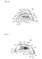
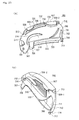
- the connecting bar controlling means 507 is preferably arranged, for example, at a position relative to an upper portion of the tag-attaching pin controlling means 710 and as shown in Fig. 20, for example, it is also preferable that the connecting bar controlling means 507 can comprise a guide wall portion (a first guide wall portion) 508 for forming a arranged locus configuration of the connecting bar 24 having a predetermined height and arranged along an outer edge portion 512 of a base plate 511 of the tag-attaching pin controlling means 710 and a connecting bar locus configuration holding means 509-1 and 509-2 which is provided on a part of a free end edge portion 513 of the guide wall portion 508 and formed in parallelism with a surface of the base plate 511.
- the height of the guide wall portion 508 is not specifically restricted to a predetermined value though, it can be designed, for example, to have a desired height taking into account of a length of a connecting portion 11 which is connecting the inserting head section 2 or 13 to the connecting bar 24 in the a sheet of tag-attaching pins 701.
- an auxiliary guide wall portion (a second guide wall portion) 510 which can keep the locus configuration of the connecting bars 24 at a prescribed shape, is provided.
- a moving locus configuration controlling means 730 for controlling a movement of the insertion section 2 of the tag-attaching pin 1 is provided between the guide wall portion 508 and the connecting bar locus configuration holding means 509-1 and 509-2.
- a moving locus configuration of the sheet of tag-attaching pins 701 can be precisely controlled and it makes a smooth movement of the sheet of tag-attaching pins 701 possible.
- the apertures 731, 732 or 733 aiming to form thickness reduction portion or weight reduction portion each of which commonly providing some kind of design can be provided.
- a portion assigned with a reference number of 734 as shown in Fig. 20 shows a suitable design portion.
- the tag-attaching pin controlling means 710 of this illustrated embodiment since it adopts the above-mentioned constructions, when the a sheet of tag-attaching pins 701 is mounted on the apparatus 20 for attaching a tag-attaching pin, a part of the connecting bar 24 of the sheet of tag-attaching pins 701 is forced to be arranged along the guiding groove 540 formed between the first and the second guiding walls 508 and 510, and thus the arranged locus configuration thereof is stably fixed and accordingly, the problems in that the sheet 701 is swung or is dropped out from the apparatus during an operation can be effectively prevented.
- the arranged locus configuration 740 formed by the connecting bar 24 of the a sheet of tag-attaching pins 701 created by the attachment 700 ⁇ is preferably configured so that an angle ⁇ formed between the arranged locus configuration formed by the connecting bar 24 of the a sheet 701 and a normal line P with respect to a top upper surface 504 of the apparatus 20 is set at within 5 to 45 degree.
- a configuration of a portion of the peripheral edge portion of the tag-attaching pin controlling means 710 and which is a portion close to a front end portion of the apparatus 20 is preferably formed to have a configuration which is curved directing to a rear portion of the tag-attaching pin controlling means 710 so that the predetermined angle ⁇ can be obtained.
- the attachment 700 of the present invention comprises the tag-attaching pin controlling means 710 and the connecting portion 503 each being integrally formed with each other and made of plastic material or metallic material or a composite material comprising the above-mentioned materials.
- a connecting means which can be fixedly coupled with, and easily decoupled from, either one of the first coupling means 703 or the second coupling means 705 provided on at least one of the side wall surfaces 501 and 529 of the apparatus for attaching a tag-attaching pin 20.
- the first coupling means 703 and 705 of the present invention is formed by a projecting portion or a recessed portion having a suitable height or a depth formed integrally with a surface of the side wall surface 501 or 529 of the apparatus 20, and the plane configuration thereof is preferably either one of a rectangular shape, a circular shape, a polygonal shape, an oval shape or the like.
- the second coupling means reception portion 706 which are provided on the first and second supporting members 702 and 707 and which can be detachably coupled with the first and the second coupling means 703 and 705, respectively, preferably has a plane configuration being substantially identical to that of the first and the second coupling means 703 and 705.
- the tag-attaching pin controlling means 710 of the attachment 700 can be fixedly connected to the side wall surfaces 501 and 529 of the apparatus 20 and the top upper surface 504 thereof via the first supporting member 702 and the second supporting member 707 and the attaching/detaching operation supporting member 712.
- an auxiliary supporting member 532 which has a configuration identical to the configuration having a slightly curved shape shown by the top upper surface of the apparatus for attaching a tag-attaching pin is provided.
- a supporting plate 720 formed by a part of the base plate 511 which is extended downwardly therefrom and having a suitable length in downwardly direction is preferably provided.
- the tag-attaching pin controlling means 710 can be more fixedly connected to the top upper surface 504 of the apparatus 20.
- the auxiliary supporting member 532 is configured so that it can be detachably contacted tightly with a top upper surface 504 of the apparatus 20.
- the attachment 700 of this embodiment to the apparatus for attaching a tag-attaching pin 20.
- the projecting portion 704 forming the first coupling means reception portion and provided inside portion of the first supporting member 702 of the attachment 700 is inserted into a hole portion 703 forming the first coupling means and provided on a front end portion of the apparatus 20 so as to couple them with each other, by rotating the main body of the attachment 700 in a counter clockwise direction as shown in Fig.
- the second supporting member 707 is abutted to the second side wall surface 529 of the apparatus 20 and slid downwardly, at the same time the projecting portion 706 forming the second coupling means reception portion provided on the second supporting member 707 is engaged with the hole portion 705 forming the second coupling means provided on a part of the second side wall surface 529 of thee apparatus 20.
- an operator pushes an operating projection portion 714 provided on the attaching/detaching operation supporting member 712 to release the coupling condition between the fourth coupling means 713 and the fourth coupling means reception portion 716, and then the operator picks up the overall tag-attaching pin controlling means 710 upwardly and rotates it in a clockwise direction which is an opposite direction when it is attached to the apparatus 20, thereby the coupling condition formed between the second supporting member 707 and the second side wall surface 529 of the apparatus 20 is also released.
- the attachment 700 can be detached from the apparatus 20.
- the second supporting member 528 of this embodiment is preferably connected to a part of the free end portion of the auxiliary supporting member 532.
- an apparatus 20 for attaching a tag-attaching pin on which the attachment 500 or 700 as defined by the present invention is detachably connected In a further separate embodiment of the present invention, an apparatus 20 for attaching a tag-attaching pin on which the attachment 500 or 700 as defined by the present invention is detachably connected.
- an operator picks up a sheet of tag-attaching pins 600 from a storing area therefore and inserts the connecting bar 24 of the sheet 600 into the slit portion 40 and 41 provided on the apparatus 20.
- a specific embodiment of the attachment 700 or 500 is preferably the one as shown in Fig. 5, when a sheet of tag-attaching pins 600 as shown in Fig. 12 is used and an apparatus 20 which is suitable for using this sheet 600 is used.
- the illustrated embodiment of Fig. 13 is used for shooting out each one of the tag-attaching pins 1 one by one by way of an apparatus 20 for attaching a tag-attaching pin as shown in Fig. 16, the attachment 700 is necessarily connected to the side wall surface of the apparatus 20 which is close to the position at which the inserting section 13 is arranged.
- the attachment 500 or 700 when the apparatus for attaching a tag-attaching pin is sold, the attachment 500 or 700 can be sold as a subordinate good of the apparatus 20 and thus both can be sold in a form of a set or the attachment 500 or 700 can also be sold separately from the selling of the apparatus 20 as an optional good.
Landscapes
- Labeling Devices (AREA)
- Basic Packing Technique (AREA)
Applications Claiming Priority (2)
| Application Number | Priority Date | Filing Date | Title |
|---|---|---|---|
| JP2004328414 | 2004-11-12 | ||
| JP2005110796A JP2006160367A (ja) | 2004-11-12 | 2005-04-07 | 係止片取付装置のアタッチメント |
Publications (2)
| Publication Number | Publication Date |
|---|---|
| EP1659066A2 true EP1659066A2 (fr) | 2006-05-24 |
| EP1659066A3 EP1659066A3 (fr) | 2006-07-26 |
Family
ID=36084171
Family Applications (1)
| Application Number | Title | Priority Date | Filing Date |
|---|---|---|---|
| EP05256979A Withdrawn EP1659066A3 (fr) | 2004-11-12 | 2005-11-11 | Dispositif utilisé dans un appareil pour attacher des étiquettes à ficelle |
Country Status (3)
| Country | Link |
|---|---|
| US (1) | US7380694B2 (fr) |
| EP (1) | EP1659066A3 (fr) |
| JP (1) | JP2006160367A (fr) |
Families Citing this family (2)
| Publication number | Priority date | Publication date | Assignee | Title |
|---|---|---|---|---|
| JP5191707B2 (ja) * | 2007-08-10 | 2013-05-08 | 株式会社トスカ | 係止ピン材の装着装置 |
| CN102046475B (zh) * | 2008-05-28 | 2014-12-10 | M.I.T.国际有限公司 | 扣合片安装装置 |
Citations (2)
| Publication number | Priority date | Publication date | Assignee | Title |
|---|---|---|---|---|
| JPS5746728A (en) | 1980-09-01 | 1982-03-17 | Japan Banok Shokai Kk | Mounting machine for connecting piece |
| JP2000085733A (ja) | 1998-09-08 | 2000-03-28 | Kootex:Kk | 係止片取付機 |
Family Cites Families (22)
| Publication number | Priority date | Publication date | Assignee | Title |
|---|---|---|---|---|
| US2729177A (en) * | 1951-10-31 | 1956-01-03 | Dennison Mfg Co | Tag attaching device |
| US3103666A (en) * | 1961-12-28 | 1963-09-17 | Dennison Mfg Co | Tag attaching apparatus |
| US3659769A (en) * | 1970-04-17 | 1972-05-02 | Dennison Mfg Co | Fastener attachment systems |
| US3650452A (en) * | 1970-09-30 | 1972-03-21 | Monarch Marking Systems Inc | Tag attacher |
| US3759435A (en) * | 1971-08-05 | 1973-09-18 | Dennison Mfg Co | Apparatus for dispensing fasteners |
| US3924788A (en) * | 1974-06-07 | 1975-12-09 | Japan Banok Co Ltd | Tag attacher |
| US4121487A (en) * | 1975-07-10 | 1978-10-24 | Dennison Manufacturing Company | Continuously connected fastener attachment stock |
| US4049179A (en) * | 1976-05-11 | 1977-09-20 | Monarch Marking Systems, Inc. | Tag attaching apparatus |
| US4288017A (en) * | 1977-08-24 | 1981-09-08 | Dennison Manufacturing Company | Method and apparatus for dispensing fasteners |
| JPS5929489B2 (ja) * | 1979-09-26 | 1984-07-20 | 株式会社サト−ゴ−セ− | 係止片の取り付け方法及び装置 |
| US4492330A (en) * | 1982-02-01 | 1985-01-08 | Japan Bano'k Co., Ltd. | Fastener attacher |
| EP0350545B1 (fr) | 1988-07-12 | 1992-12-16 | Japan Bano'k Co. Ltd. | Appareil pour attacher des étiquettes à ficelle |
| US5024365A (en) * | 1989-09-15 | 1991-06-18 | Dennison Manufacturing Company | Apparatus for dispensing fasteners |
| US5033664A (en) * | 1989-09-15 | 1991-07-23 | Dennison Manufacturing Company | Dispensing of attachment members |
| US5339954A (en) * | 1993-01-29 | 1994-08-23 | Steven Kunreuther | Clip of attachments |
| US5501002A (en) * | 1994-06-20 | 1996-03-26 | Fukami; Syouichi | Tag fastening device |
| JP3014628B2 (ja) * | 1995-09-19 | 2000-02-28 | キヤノン株式会社 | 太陽電池用端子取出し箱 |
| KR100425671B1 (ko) | 1996-08-22 | 2004-06-16 | 코텍스 가부시키가이샤 | 계지편부착기 |
| US5826775A (en) * | 1997-05-08 | 1998-10-27 | Mooney; Linda | Sock clip system |
| JP4059551B2 (ja) | 1997-11-10 | 2008-03-12 | 株式会社コーテックス | 係止片構造体 |
| US6126056A (en) | 1999-11-10 | 2000-10-03 | Kotec's Co., Ltd. | Apparatus for attaching tag pins |
| US6561406B1 (en) | 2000-06-13 | 2003-05-13 | Akira Furutsu | Lock member attachment device and lock member used therefor |
-
2005
- 2005-04-07 JP JP2005110796A patent/JP2006160367A/ja active Pending
- 2005-11-10 US US11/272,117 patent/US7380694B2/en not_active Expired - Fee Related
- 2005-11-11 EP EP05256979A patent/EP1659066A3/fr not_active Withdrawn
Patent Citations (2)
| Publication number | Priority date | Publication date | Assignee | Title |
|---|---|---|---|---|
| JPS5746728A (en) | 1980-09-01 | 1982-03-17 | Japan Banok Shokai Kk | Mounting machine for connecting piece |
| JP2000085733A (ja) | 1998-09-08 | 2000-03-28 | Kootex:Kk | 係止片取付機 |
Also Published As
| Publication number | Publication date |
|---|---|
| JP2006160367A (ja) | 2006-06-22 |
| US7380694B2 (en) | 2008-06-03 |
| EP1659066A3 (fr) | 2006-07-26 |
| US20060113349A1 (en) | 2006-06-01 |
Similar Documents
| Publication | Publication Date | Title |
|---|---|---|
| RU2344740C2 (ru) | Система для закрепления вспомогательного оборудования на полке | |
| EP2022721B1 (fr) | Dispositif pour la pose d'éléments de fixation | |
| EP1088762A1 (fr) | Dispositif adhesif | |
| EP1338519B1 (fr) | Pistolet de fixation d'épingles en boucle | |
| KR100679188B1 (ko) | 플라스틱 패스너 분배 공구 | |
| EP1659066A2 (fr) | Dispositif utilisé dans un appareil pour attacher des étiquettes à ficelle | |
| EP2301851A1 (fr) | Dispositif de fixation pour pièce de blocage | |
| US4492330A (en) | Fastener attacher | |
| EP1378453B1 (fr) | Pistolet de fixation d'épingles en boucle | |
| EP1366994A1 (fr) | Dispositif de pose d'attaches | |
| US6009997A (en) | Loop fastener, fastener clip including same and loop fastener dispensing tool | |
| EP1489013B1 (fr) | Pistolet de fixation d'épingles en boucle | |
| EP1145965B1 (fr) | Elément de fixation | |
| US20050141952A1 (en) | File mechanism | |
| US20080302851A1 (en) | Fastening element attaching device | |
| EP1083537A2 (fr) | Instrument de scellage | |
| WO2002016211A1 (fr) | Aiguille destinee a etre utilisee dans un outil distributeur d'attaches en plastique | |
| JP3570924B2 (ja) | 商品移動具 | |
| EP1590131A2 (fr) | Dispositif de fixation | |
| TW201805124A (zh) | 裝訂機 | |
| JP2025035114A (ja) | プライスカードレール | |
| HK1075235B (en) | Tool for dispensing plastic fasteners | |
| JP3751846B2 (ja) | 係止部材の装着装置 | |
| NL8200513A (nl) | Aanhechters voor verbinders. |
Legal Events
| Date | Code | Title | Description |
|---|---|---|---|
| PUAI | Public reference made under article 153(3) epc to a published international application that has entered the european phase |
Free format text: ORIGINAL CODE: 0009012 |
|
| AK | Designated contracting states |
Kind code of ref document: A2 Designated state(s): AT BE BG CH CY CZ DE DK EE ES FI FR GB GR HU IE IS IT LI LT LU LV MC NL PL PT RO SE SI SK TR |
|
| AX | Request for extension of the european patent |
Extension state: AL BA HR MK YU |
|
| PUAL | Search report despatched |
Free format text: ORIGINAL CODE: 0009013 |
|
| AK | Designated contracting states |
Kind code of ref document: A3 Designated state(s): AT BE BG CH CY CZ DE DK EE ES FI FR GB GR HU IE IS IT LI LT LU LV MC NL PL PT RO SE SI SK TR |
|
| AX | Request for extension of the european patent |
Extension state: AL BA HR MK YU |
|
| 17P | Request for examination filed |
Effective date: 20060914 |
|
| 17Q | First examination report despatched |
Effective date: 20061018 |
|
| AKX | Designation fees paid |
Designated state(s): DE FR GB IT |
|
| GRAP | Despatch of communication of intention to grant a patent |
Free format text: ORIGINAL CODE: EPIDOSNIGR1 |
|
| STAA | Information on the status of an ep patent application or granted ep patent |
Free format text: STATUS: THE APPLICATION IS DEEMED TO BE WITHDRAWN |
|
| 18D | Application deemed to be withdrawn |
Effective date: 20110929 |