EP1088762A1 - Dispositif adhesif - Google Patents
Dispositif adhesif Download PDFInfo
- Publication number
- EP1088762A1 EP1088762A1 EP00904044A EP00904044A EP1088762A1 EP 1088762 A1 EP1088762 A1 EP 1088762A1 EP 00904044 A EP00904044 A EP 00904044A EP 00904044 A EP00904044 A EP 00904044A EP 1088762 A1 EP1088762 A1 EP 1088762A1
- Authority
- EP
- European Patent Office
- Prior art keywords
- filament
- unit
- implement according
- sealing implement
- sealing
- Prior art date
- Legal status (The legal status is an assumption and is not a legal conclusion. Google has not performed a legal analysis and makes no representation as to the accuracy of the status listed.)
- Granted
Links
- 238000007789 sealing Methods 0.000 claims abstract description 266
- 238000003780 insertion Methods 0.000 claims abstract description 87
- 230000037431 insertion Effects 0.000 claims abstract description 87
- 230000007246 mechanism Effects 0.000 claims description 93
- 230000002265 prevention Effects 0.000 claims description 46
- 229920003002 synthetic resin Polymers 0.000 claims description 13
- 239000000057 synthetic resin Substances 0.000 claims description 13
- 239000000463 material Substances 0.000 claims description 7
- 241000209149 Zea Species 0.000 claims description 4
- 235000005824 Zea mays ssp. parviglumis Nutrition 0.000 claims description 4
- 235000002017 Zea mays subsp mays Nutrition 0.000 claims description 4
- 235000005822 corn Nutrition 0.000 claims description 4
- 238000010008 shearing Methods 0.000 claims description 3
- 230000015572 biosynthetic process Effects 0.000 claims 1
- 238000005452 bending Methods 0.000 description 4
- 230000000694 effects Effects 0.000 description 3
- 230000013011 mating Effects 0.000 description 2
- 239000004677 Nylon Substances 0.000 description 1
- 239000004743 Polypropylene Substances 0.000 description 1
- 230000001154 acute effect Effects 0.000 description 1
- 238000005520 cutting process Methods 0.000 description 1
- 230000007257 malfunction Effects 0.000 description 1
- 229920001778 nylon Polymers 0.000 description 1
- 229920000728 polyester Polymers 0.000 description 1
- -1 polypropylene Polymers 0.000 description 1
- 229920001155 polypropylene Polymers 0.000 description 1
Images


Classifications
-
- G—PHYSICS
- G09—EDUCATION; CRYPTOGRAPHY; DISPLAY; ADVERTISING; SEALS
- G09F—DISPLAYING; ADVERTISING; SIGNS; LABELS OR NAME-PLATES; SEALS
- G09F3/00—Labels, tag tickets, or similar identification or indication means; Seals; Postage or like stamps
- G09F3/02—Forms or constructions
- G09F3/03—Forms or constructions of security seals
- G09F3/0305—Forms or constructions of security seals characterised by the type of seal used
- G09F3/037—Forms or constructions of security seals characterised by the type of seal used having tie-wrap sealing means
-
- B—PERFORMING OPERATIONS; TRANSPORTING
- B65—CONVEYING; PACKING; STORING; HANDLING THIN OR FILAMENTARY MATERIAL
- B65C—LABELLING OR TAGGING MACHINES, APPARATUS, OR PROCESSES
- B65C7/00—Affixing tags
-
- B—PERFORMING OPERATIONS; TRANSPORTING
- B65—CONVEYING; PACKING; STORING; HANDLING THIN OR FILAMENTARY MATERIAL
- B65C—LABELLING OR TAGGING MACHINES, APPARATUS, OR PROCESSES
- B65C7/00—Affixing tags
- B65C7/003—Affixing tags using paddle-shaped plastic pins
- B65C7/005—Portable tools
-
- G—PHYSICS
- G09—EDUCATION; CRYPTOGRAPHY; DISPLAY; ADVERTISING; SEALS
- G09F—DISPLAYING; ADVERTISING; SIGNS; LABELS OR NAME-PLATES; SEALS
- G09F3/00—Labels, tag tickets, or similar identification or indication means; Seals; Postage or like stamps
- G09F3/08—Fastening or securing by means not forming part of the material of the label itself
- G09F3/14—Fastening or securing by means not forming part of the material of the label itself by strings, straps, chains, or wires
-
- Y—GENERAL TAGGING OF NEW TECHNOLOGICAL DEVELOPMENTS; GENERAL TAGGING OF CROSS-SECTIONAL TECHNOLOGIES SPANNING OVER SEVERAL SECTIONS OF THE IPC; TECHNICAL SUBJECTS COVERED BY FORMER USPC CROSS-REFERENCE ART COLLECTIONS [XRACs] AND DIGESTS
- Y10—TECHNICAL SUBJECTS COVERED BY FORMER USPC
- Y10S—TECHNICAL SUBJECTS COVERED BY FORMER USPC CROSS-REFERENCE ART COLLECTIONS [XRACs] AND DIGESTS
- Y10S206/00—Special receptacle or package
- Y10S206/82—Separable, striplike plural articles
Definitions
- the present invention relates to a sealing implement for sealing by affixing a tag such as a brand label, price tag, material explanation, or handling instructions to a product such as a garment, shoes, or bag, and more particularly it relates to a sealing implement capable of performing an operation of smoothly affixing a tag when the above-noted tag is set into a special attachment apparatus (gun).
- a tag such as a brand label, price tag, material explanation, or handling instructions
- a product such as a garment, shoes, or bag
- such an implement can have a configuration formed by a filament 5 forming a loop that is passed through a tag, an insertion head part 6 formed on one end the filament 5 and a socket part 8 having an insertion hole 7 for the purpose of passing the insertion head part 6, provided on the other end of the filament 5.
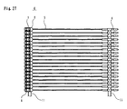
- a plurality of single sealing implements which forming an unit of sealing implement 4 are temporarily attached to two mutually parallel connection bars 11 so as to enable removal therefrom.
- An embodiment of the sealing implement as shown in Fig. 27, can be integrally formed of a synthetic resin, and in particular the filament part 5 thereof is drawn and exhibits extremely high strength with respect to pulling tension.
- a pair of skirts 9 serving as hook portions and which being provided on the insertion head part 19, is opened and thereby the insertion head part 19 is irreversibly fixed inside the socket part 8, thereby completing the sealing, in a condition in which the label is affixed with the implement forming a loop.
- sealing implements were loaded into a special ejecting apparatus (attachment gun), a lever thereof being pulled, thereby enabling use chiefly in bundling of such items as boots, sandals, and shoes, and also in fixing of a price tag, or a tag T having instructions for use of the product to the product.
- attachment gun attachment gun
- the unit of sealing implements is to be mounted on a gun which is exclusively used for continuously sealing the sealing implement by operating a lever of the gun, the unit of sealing implements is to be bent with relatively strong force first and thereafter, the insertion head part 6 should be mounted on one end of the gun while the socket part 8 should be mounted on another end of the gun and this work was heavy work for the operator.
- the filament portion of the unit of sealing implement forming a flat condition is to be bended, the filament portion is relatively hard so that there must be a limitation in a radius of curvature to be set and thus a width of the gun cannot be significantly shortened.
- a second object of the present invention is to improve the operational characteristic of the unit of sealing implement when the single sealing implement is respectively attached to a commercial good.
- the present invention adopts the following base technical constitution.
- a first aspect of the present invention is such that an unit of sealing implement comprising a plurality of single sealing implements each one of which comprising, a flexible filament part, an insertion head part having an appropriate engaging part provided on one end part of the filament part, and a socket part having a hole for the purpose of irreversibly inserting the insertion head part provided on another end of the filament, wherein a plurality of the single sealing implements are mutually and adjacently arranged in parallel with each other and each of the plurality of insertion head parts or a portion proximity thereto and each of the plurality of socket parts or a portion proximity thereto being caused to be connected to separately provided connecting bars, and further wherein a filament part of the unit of sealing implement showing curvilinear configuration or at least one portion of the filament part thereof provided with a folded portion.
- a second aspect of the present invention is such that an unit of sealing implement comprising a plurality of single sealing implements each one of which comprising, a flexible filament part, an insertion head part having an appropriate engaging part provided on one end part of the filament part, and a socket part having a hole for the purpose of irreversibly inserting the insertion head part provided on another end of the filament, wherein a plurality of the single sealing implements are mutually and adjacently arranged in parallel with each other and each of the plurality of insertion head parts or a portion proximity thereto and each of the plurality of socket parts or a portion proximity thereto being caused to be connected to separately provided connecting bars, and further wherein at least a part of the filament part of the unit of sealing implement being provided with a filament deforming mechanism which can easily deform the filament part into a curvilinear or folded configuration, irreversibly.
- a third aspect of the present invention is such that a single sealing implement which comprising, a flexible filament part, an insertion head part having an appropriate engaging part provided on one end part of the filament part, and a socket part having a hole for the purpose of irreversibly inserting the insertion head part provided on another end of the filament, wherein at least a part of the filament part being provided with a bended portion at which the prat of the filament part being irreversibly curved or bended into a predetermined configuration, and further wherein, both of the filament part connected to the socket part and the filament part connected to the insertion head part substantially showing linear configuration, respectively.
- a fourth aspect of the present invention is such that an unit of sealing implement comprising a plurality of single sealing implements each one of which comprising, a flexible filament part, an insertion head part having an appropriate engaging part provided on one end part of the filament part, and a socket part having a hole for the purpose of irreversibly inserting the insertion head part provided on another end of the filament, wherein a plurality of the single sealing implements are mutually and adjacently arranged in parallel with each other and each of the plurality of insertion head parts or a portion proximity thereto and each of the plurality of socket parts or a portion proximity thereto being caused to be connected to separately provided connecting bars, and wherein at least a part of the filament part of the unit of sealing implement being provided with a curvilinear configured portion or a folded portion, and further wherein at least a part of the filament part of the unit of sealing implement being provided with a filament jamming prevention mechanism whereby a plurality of the filament part adjacently arranged to each other are prevented from jamming each other.
- a fifth aspect of the present invention is such that an unit of sealing implement comprising a plurality of single sealing implements each one of which comprising, a flexible filament part, an insertion head part having an appropriate engaging part provided on one end part of the filament part, and a socket part having a hole for the purpose of irreversibly inserting the insertion head part provided on another end of the filament, wherein a plurality of the single sealing implements are mutually and adjacently arranged in parallel with each other and each of the plurality of insertion head parts or a portion proximity thereto and each of the plurality of socket parts or a portion proximity thereto being caused to be connected to separately provided connecting bars, and wherein at least a part of the filament part of the unit of sealing implement being provided with a filament deforming mechanism which can easily deform the filament part into a curvilinear or folded configuration, irreversibly, and further wherein at least a part of the filament part of the unit of sealing implement being provided with a filament jamming prevention mechanism whereby a plurality of the filament part adjacently arranged
- the present invention has a basic feature of the present invention in that an unit of sealing implement comprising a plurality of single sealing implements each one of which comprising, a flexible filament part, an insertion head part having an appropriate engaging part provided on one end part of the filament part, and a socket part having a hole for the purpose of irreversibly inserting the insertion head part provided on another end of the filament, wherein a plurality of the single sealing implements are mutually and adjacently arranged in parallel with each other and each of the plurality of insertion head parts or a portion proximity thereto and each of the plurality of socket parts or a portion proximity thereto being caused to be connected to separately provided connecting bars, and further wherein a filament part of the unit of sealing implement showing curvilinear configuration or at least one portion of the filament part thereof provided with a folded portion.
- the unit of sealing implement as mentioned above can be easily mounted on an attachment shooting gun used for shooting each one of the sealing implements (hereinafter referred to a special shooting gun).
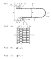
- Fig. 1 is an enlarged plan view showing an embodiment of an unit of sealing implement according to the present invention
- Fig. 2 is an enlarged front view, an enlarged side view and a perspective view each showing an embodiment of an unit of sealing implement according to the present invention, respectively.
- an unit of sealing implement 20 of the present invention comprises a plurality of single sealing implements each one of which comprising, a flexible filament part 5, an insertion head part 19 having an appropriate engaging part, for example, a blade member 9 provided on one end part of the filament part 5, and a socket part 8 having a hole 10 for the purpose of irreversibly inserting the insertion head part 19 provided on another end of the filament 5, wherein a plurality of the filament parts 5 of the single sealing implements are mutually and adjacently arranged in parallel with each other and each of the plurality of insertion head parts 19 or a portion proximity thereto and each of the plurality of socket parts 8 or a portion proximity thereto being caused to be connected to separately provided connecting bars 11, and further wherein a middle portion 5a of the filament part 5 of the unit of sealing implement 20 shows a curvilinear configuration.
- the middle portion 5a of the filament part 5 of the unit of sealing implement 20 may have a folded configuration, instead.
- a portion of the filament parts 5f which is connected to the insertion head part 19 and the filament parts 5g which is connected to the socket part 8 are arranged substantially in parallel with each other with a predetermined distance W', interposed therebetween.
- both of the insertion head part 19 and the socket part 8 are connected to the connecting bars 11 through connecting portions 11a and 11b, respectively, which can be easily cut off and removed.
- the unit of sealing implement 20 according to the present invention is integrally formed of a synthetic resin, such as the usual Nylon, polypropylene, or polyester, such as was the case with sealing implements of the past, with a plurality of the filament parts being arranged into a flat surface configuration.
- a synthetic resin such as the usual Nylon, polypropylene, or polyester, such as was the case with sealing implements of the past, with a plurality of the filament parts being arranged into a flat surface configuration.
- this configuration is irreversibly fixed, for example, by heat set or the like with utilizing a predetermined mold or a predetermined supporting means so as to give at least a portion of the filament part connecting to the the insertion head part 19 and the socket part 8, a curvilinear configuration.
- the unit of sealing implement of the present invention may be previously provided with a curvature or folding portion making support mechanism which make at least a portion of the filament part bendable easily, on at least a portion of the filament part and a heat set operation may be applied to this filament part.
- irreversibly bended means the condition in which after such heat set operation had been applied to the unit of sealing implement, the unit maintains the condition set by such heat set operation, in other word, after the heat set, and when the unit is leave in free condition, the filament part of the unit can keep its curvilinear configuration set by the heat set operation.
- W' denotes a distance with which the unit of sealing implement of the present invention can be mounted on the special gun 18 and the exact distance with which the operation efficiency for the special gun can be improved.
- a distance W formed between the grooves 21 and 22 for the connecting bars 11, 11 to be inserted thereinto should preferably be set at a distance which is identical to of substantially the same as a distance W as formed between the connecting bars 11 and 11.
- the unit of sealing implement of the present invention can be easily mounted on the special gun and can avoid mistakes such as for the unit to be erroneously inserted into the gun with a wrong insertion manner or to be erroneously inserted into the gun in an opposite direction.
- the width of the special gun 18 can be shortened causing the size of the gun compacted.
- a basic configuration of the unit of sealing implement 20 is substantially the same as that of the conventional unit of sealing implement.
- the socket part 8 has a hole 10 which can pass the insertion head part 19 therethrough, irreversibly.
- a cross sectional configuration of the filament part may be any one of configuration selected from a group of circular, flat and rectangular configurations.
- a mating part 16 which engages with an engaging portion 9 which is a part of the insertion head part 19, is provided.
- Such mating part 16 may preferably comprise a projected member or concaved member.
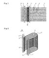
- the unit of sealing implement 20 of the present invention since a portion around the center portion of the filament part 5 is previously set at the curvilinear configuration or a configuration very closed thereto, irreversibly, it can be easily mounted on the special gun and additionally, the each filament part of the unit of sealing implement 20 is temporarily connected to the connecting bars 11 in parallel with each other.
- Fig. 4 shows a perspective view of the unit of sealing implement of the present invention, in that the unit of sealing implement 20 comprises 40 to 60 ends of filament part which being connected to the connecting bars 11.
- the number of ends of the filament part of the present invention can be varied with respect to an object to which this invention to be used.
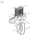
- Fig. 6 shows a plan view of a main part of the special gum using the unit of sealing implement of the present invention.
- the special gun 18 is provided with a pair of vertical grooves 21 and 22 on both sides thereof, into which a pair of the connecting bars 11, 11 are inserted, respectively.
- the connecting bar 11 which is connected to the socket part 8 of the unit of sealing implement 20 may be inserted into the vertical groove 21 while the connecting bar 11 which is connected to the insertion head part 19 of the unit of sealing implement 20 may be inserted into the vertical groove 22.
- the special gun 18 is also provided with a pushing pin mechanism 23 at a position beside the vertical groove 22 and which is driven by actuating the operational lever 18a as shown in Fig. 6 so that each one of the insertion head part 19 can be pushed forwardly by the pushing pin mechanism 23 along a hollow guide pin 24, one by one, by removing same from the connecting portion 11a formed on the connecting bar 11.
- the socket part 8 guided by the connecting bar 11 which is inserted into the vertical groove 21, is can be pushed by a pushing belt 25 forwardly along a hollow curved socket part guide 26, one by one, by removing same from the connecting portion 11b formed on the connecting bar 11 and the socket part 8 pushed out along the socket part guide 26 is changed its forward direction by 90 degree, for example, so as to couple with the insertion head part 19 pushed by the pushing pin mechanism 23 at the hole 10 thereof.
- the socket part guide 26 has a hollow tube type passage with a curvature which varies its center axis by 90 degrees so that the pushing belt 25 can easily be moved forwardly through inside thereof and it is so configured that a timing when a tip portion of the pushing belt 25 will reach at a top portion of the socket part guide 26 coincides with a timing when the pushing pin 23 will reach at the top portion of the socket part guide 26.
- each one of the single sealing implement of the unit of sealing implement 20 can continuously attach a label to a commercial good, sequentially.
- the filament part of the unit of sealing implement 20 is bended so as to set the distance formed between the connecting bars 11, 11, at a prescribed length, the unit of sealing implement can be easily mounted on the special gun 18 and further there exists a space for inserting label, the operation for attaching label to commercial goods is rendered easily.
- a curvature or folding portion making support mechanism 17 may be provided whereby the mechanism 17 enabling the portion of the filament part 5 to be easily formed into a predetermined configuration, irreversibly.
- the curvature or folding portion making support mechanism 17 of this embodiment may comprise a filament part which is made of thermally settable synthetic resin material and further it may comprise a filament part at least one portion of which has a cross sectional area having a flat type configuration including a film like configuration, a rectangular type configuration and an oval type configuration as shown in Fig. 2(C), although a cross sectional configuration thereof is usually circular configuration as shown in Fig. 2(B).
- the curvature or folding portion making support mechanism 17 of this embodiment may comprise a filament part which has a groove or a cut portion as well as may comprise a filament part which has a diameter being smaller than that of a main portion of the filament part.
- the filament part having a diameter being smaller than that of a main portion of the filament part includes a tapered portion.
- the filament parts 5g which is extended from the socket part 8 and the filament parts 5f which is extended from the insertion head part 19 show linear configuration, respectively.
- the filament parts 5g which is extended from the socket part 8 and the filament parts 5f which is extended from the insertion head part 19 are set in parallel with each other and additionally, a distance W as formed between a pair of the connecting bars 11 and 11, may preferably be set at a distance which is identical to or substantially the same as a distance as formed between the grooves 21 and 22 formed on the special gun 18 using the unit of sealing implement 20 which is mounted thereon.
- a curvature or folding portion making support mechanism 17 may be provided whereby the mechanism 17 enabling the portion of the filament part 5 to be easily formed into a predetermined configuration, irreversibly and the curvature or folding portion making support mechanism 17 of this embodiment may comprise a filament part which is made of thermally settable synthetic resin material.
- curvature or folding portion making support mechanism 17 of this embodiment may comprise a filament part which has a cross sectional area having a flat type configuration, a short axis thereof directing to a direction to which the filament part being bent as shown in Fig. 2(C) .
- the curvature or folding portion making support mechanism 17 of this embodiment may comprise a filament part which has a groove or a cut portion.
- a separate example of the curvature or folding portion making support mechanism 17 of this embodiment may comprise a filament part 5 which has a diameter being smaller than that of a main portion of the filament part and such filament part having a diameter being smaller than that of a main portion of the filament part may include a tapered portion.
- the filament part 5 having a diameter being smaller than that of a main portion of the filament part may have a cross sectional area which is smaller than that of a main portion of the filament part.
- an overall configuration of the unit of sealing implement 20 is formed integrally with synthetic resin and the socket part 8 and the insertion head part 19 are not drawn.
- socket part 8 and the insertion head part 19 may be connected to one of the respective connecting bars 11, through connecting portions being easily removed.
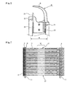
- Fig. 7 shows a front view of the second embodiment of the unit of sealing implement of the present invention.
- the unit of sealing implement 20 comprises a flexible filament part 5, an insertion head part 19 having an appropriate engaging part provided on one end part of the filament part 5, and a socket part 8 having a hole 10 for the purpose of irreversibly inserting the insertion head part 19 provided on another end of the filament 5, wherein a plurality of the single sealing implements are mutually and adjacently arranged in parallel with each other and each of the plurality of insertion head parts 19 or a portion proximity thereto and each of the plurality of socket parts 8 or a portion proximity thereto being caused to be connected to separately provided connecting bars 11, 11, and further wherein at least a part of the filament part 5 of the unit of sealing implement 20 is provided with a filament deforming mechanism 27 which can easily deform the filament part into a curvilinear or folded configuration, irreversibly.
- Fig. 8 shows the third embodiment of the present invention in that the filament deforming mechanism 27 is provided at a portion 5c, around the center part the filament part 5 with a predetermined width.
- This filament deforming mechanism 27 is made of, for example, a heat settable synthetic resin material.
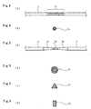
- this filament deforming mechanism 27 may comprise a filament part having a diameter being smaller than that of a main portion of the filament part 5 may have a cross sectional area which is smaller than that of a main portion of the filament part as shown in Fig. 8(A) and Fig. 8(B).
- the cross sectional area thereof shows a cross configuration.
- the cross sectional configuration is made relatively small so as to make a cross-sectional secondary moment small causing the filament part to be easily bended at this portion.
- Fig. 9 shows the fourth embodiment of the unit of sealing implement of the present invention
- Fig. 9(A) is a plan view showing a main portion of a filament part of the single sealing implement
- Fig. 9(B) shows a cross-section of a main portion of a filament part
- Fig. 9 (C) and Fig. 9 (D) show a cross-section of a main portion of a separate embodiment and a further separate embodiment of a filament part of the single sealing implement, respectively.
- the portion around a center of the filament part 5 has a diameter being smaller than that of a main portion of the filament part 5 and further has a tapered portion 5e in which thickness of a normal filament part 5 is gradually reduced to the portion 5d thereof having a small diameter.
- the filament deforming mechanism 27 of this embodiment may comprise a filament part 5 made of heat settable synthetic resin and further may comprise a filament part 5 which has a flat type cross sectional configuration or an oval type configuration which having a long axis thereof being perpendicular to a bending direction of the filament part 5.
- filament deforming mechanism 27 of this embodiment may comprise a filament part 5 at least one portion of which having a groove or cut portion as well as it 20 may be formed integrally with synthetic resin.
- socket part 8 and the insertion head part 19 may be connected to one of the respective connecting bars 11, through connecting portions being easily removed.
- the filament deforming mechanism 27 may comprise a filament part 5d which has a diameter being smaller than that of a main portion of the filament part 5 and such filament part 5d having a diameter being smaller than that of a main portion of the filament part may include a tapered portion 5e.
- the filament part 5d having a diameter being smaller than that of a main portion of the filament part 5 may have a cross sectional area which is smaller than that of a main portion of the filament part 5.
- the cross sectional configurations of the filament part 5d having a diameter being smaller than that of a main portion of the filament part 5 may be any one of the configurations selected from the group of a star type configuration, a triangle type configuration and a rectangular configuration as shown in Fig. 9 (B), (C) and (D), respectively.
- a cross-sectional secondary moment of the filament part 5d having a diameter being smaller than that of a main portion of the filament part 5 and the tapered portion 5e become relatively small so as to reduce the filament part to be easily bended and heat set.
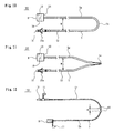
- Fig. 10 shows a plan view of the fifth embodiment of the present invention.
- the fifth embodiment of the present invention relates to a single sealing implement which comprises a filament part 5, an insertion head part 19 having an appropriate engaging part 19a provided on one end part of the filament part 5, and a socket part 8 having a hole 10 for the purpose of irreversibly inserting the insertion head part 19 provided on another end of the filament 5, wherein at least a part of the filament part 5 is provided with a bended portion 5k at which the prat of the filament part 5 is irreversibly curved or bended into a predetermined configuration, and further wherein, both of the filament part 5f connected to the socket part 8 and the filament part 5g connected to the insertion head part 19 substantially show a linear configuration, respectively.
- one of sealing implement 30 which are component of the unit of sealing implement 20 can be separately formed and this single sealing implement 30 may be used for attaching tag to a commercial good by manual operation, for example.
- the single sealing implement 30 comprises filament part 5, an insertion head part 19 having an appropriate engaging part provided on one end part of the filament part 5, and a socket part 8 having a hole 10 for the purpose of irreversibly inserting the insertion head part 19 provided on another end of the filament 5, wherein at least a part of the filament part 5 is provided with a bended portion 5k at which the prat of the filament part 5 is irreversibly curved or bended into a predetermined configuration, and further wherein, both of the filament part 5f connected to the socket part 8 and the filament part 5g connected to the insertion head part 19 substantially show a linear configuration, respectively.
- One example of the bended portion 5k may comprise a portion of the filament part 5 which has a cross section having a flat type configuration or a oval type configuration.
- the bended portion 5k may comprise a filament part 5 at least one portion of which having a groove or cut portion as well as it 5k may comprise a filament part 5d which has a diameter being smaller than that of a main portion of the filament part 5 and such filament part 5d having a diameter being smaller than that of a main portion of the filament part.
- the bended portion 5k may comprise a filament part 5 which includes a tapered portion.
- the single sealing implement 30 is provided with a finger contact grasping portion 50 to which a tip portion of a finger of an operator is contacted, and which has a substantial rectangular configuration in a direction from the socket part 8 to the filament part 5 and when the single sealing implement 30 is picked up by a finger of an operator, a tip portion of a finger of the operator is preferentially contacted to the finger contact grasping portion 50.
- the socket part 8 is necessarily fixed on an upper position of a tip portion of the operator's finger.
- Fig. 11 shows a plan view of the sixth embodiment of the present invention.
- both of the filament part 5g extending from the socket part 8 and the filament part 5f extended from the insertion head part 19 substantially are formed and arranged in substantially parallel with each other with a predetermined distance W' interposed therebetween and the center portion 5c of the filament part 5 is folded with an acute angle.
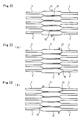
- Fig. 12 shows a plan view of an embodiment of a single sealing implement 30 in which a filament jamming prevention mechanism is provided on a curvilineare portion of a filament part
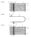
- Fig. 13 shows a side view of an unit of sealing implement comprising a plurality of the single sealing implement as mentioned above.
- an unit of sealing implement comprising a plurality of single sealing implements each one of which comprising, a filament part 5, an insertion head part 19 having an appropriate engaging part provided on one end part of the filament part 5, and a socket part 8 having a hole 10 for the purpose of irreversibly inserting the insertion head part 19 provided on another end of the filament 5, wherein a plurality of the single sealing implements are mutually and adjacently arranged so that each of the filament part 5 being arranged in parallel with each other and each of the plurality of insertion head parts 19 or a portion proximity thereto and each of the plurality of socket parts 8 or a portion proximity thereto being caused to be connected to separately provided connecting bars 11, and wherein at least a part of the filament part 5 of the unit of sealing implement being provided with a curvilinear configured portion or a folded portion, and further wherein at least a part of the filament part 5 of the unit of sealing implement being provided with a filament jamming prevention mechanism 40 whereby a plurality of the filament part 5 adjacently arranged to each
- two spherical portions 40 separated from each other with a predetermined distance m are provided at a center portion of the curvilineare portion of the filament part 5.
- Each of the spherical portions 40 formed on each one of the filament parts 5 adjacently arranged to each other when they are associated into the unit of sealing implement, are connected to each other in a vertical direction utilizing a connection portion 32.
- Fig. 14 shows a plan view of another embodiment of an unit of sealing implement in which a filament jamming prevention mechanism is provided on a curvilineare portion of each one of a filament part and Fig. 15 shows a side view of the unit of sealing implement as shown in Fig. 14.
- a portion of the filament part which has an extended portion 41 having a cross section of a rectangular configuration is provided along a predetermined length.
- a maximum diameter of the extended portion 41 is preferably smaller than a hole provided on the label, for example, 1.9 to 2.0 mm.
- a plurality of the extended portion 41 each adjacently arranged to each other for example in a vertical direction, may be connected with each other via a connection portion 32.
- Fig. 16 (A) shows a plan view of a separate embodiment of an unit of sealing implement in which a filament jamming prevention mechanism is provided on a filament part of the present invention and Fig. 17 shows a side view of the unit of sealing implement as shown in Fig. 16 (A).
- the portion thereof is bent with a V shaped configuration and the V shaped vent portion is provided with an extended portion 42.
- each one of the extended portions 42 adjacently arranged vertically are connected to each other with a connecting member 32.
- insertion head parts 19 and the socket parts 8 insertion head parts single sealing implements 5 may be arranged in parallel with each other with respect to the V shaped filament part 5.
- Fig. 16 (B) shows a plan view of an another embodiment of an unit of sealing implement in which both end portions of a filament part 5 are arranged in parallel with each other for a prescribed length thereof and a center portion or around the center portion of the filament part is vent with a V charactered configuration and at the same place, a V shaped vendt portion is provided with an extended portion 42 a.
- Fig. 16 (C) shows a plan view of a further separate embodiment of an unit of sealing implement of the present invention, in which both end portions of a filament part 5 are arranged in parallel with each other for a prescribed length thereof and a center portion or around the center portion of the filament part is vent with a V charactered configuration and at the same place, a U shaped extended portion 42b is provided.
- Fig. 18 shows a front view of a seventh embodiment of an unit of sealing implement of the present invention.
- an unit 60 of sealing implement comprising a plurality of single sealing implements each one of which comprising, a flexible filament part 5, an insertion head part 19 having an appropriate engaging part provided on one end part of the filament part 5, and a socket part 8 having a hole 10 for the purpose of irreversibly inserting the insertion head part 19 provided on another end of the filament, wherein a plurality of the single sealing implements are mutually and adjacently arranged in parallel with each other and each of the plurality of insertion head parts 19 or a portion proximity thereto and each of the plurality of socket parts 8 or a portion proximity thereto being caused to be connected to separately provided connecting bars 11, and further wherein at least a part of the filament part 5 of the unit of sealing implement being provided with a filament deforming mechanism 28 which can easily deform the filament part into a curvilinear or folded configuration, irreversibly, and further wherein at least a part of the filament part 5 of the unit of sealing implement being provided with a filament jamming prevention mechanism 29 whereby a plurality of the single sealing implements
- a filament jamming prevention mechanism 29 on at least a part of the filament part 5, a filament jamming prevention mechanism 29, whereby a plurality of the filament parts 5 adjacently arranged to each other are prevented from jamming each other.
- these spherical portion 29 contributes to prevent a plurality of the filament parts arranged in parallel to each other from being intermingeled with each other when the filament parts 5 is vent.
- Fig. 19 shows a front view of an eighth embodiment of an unit of sealing implement of the present invention.
- two spherical portions 29 having a diameter being larger than a diameter of the filament part 5, and which serve as the filament jamming prevention mechanism 29, which can prevent a plurality of the filament parts5 adjacently arranged to each other from being jammed or intermingeled with each other, are provided on the filament part therealong with a prescribed distance interposed therebetween.
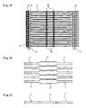
- Fig. 20 shows an enlarged front view of a main portion of a ninth embodiment of an unit of sealing implement of the present invention
- Fig. 21 shows an enlarged front view of a main portion of a tenth embodiment of an unit of sealing implement of the present invention.
- a plate like enlarged portion 31 having a polygonal configuration is provided as the filament jamming prevention mechanism 29.
- This plate like enlarged portion 31 has a width as same as a width of th filament part 5 and a heigh a value of which is set so that each one of the plate like enlarged portions 31 each adjacently being arranged to each other without contacting with each other in a vertical direction.
- the filament parts 5 is prevented from being intermingeled with each other when the filament parts 5 is vent.
- Fig. 22 shows an enlarged front view of a main portion of a eleventh embodiment of an unit of sealing implement of the present invention.
- the connecting member 32 has a strength whereby the connecting member 32 is easily cut off when the unit of single sealing implements is mounted on the shooting gun 18 thereof.
- the connecting member 32 is provided at a center or in a vicinity of the center of the plate like enlarged portion 31.
- the connecting member 32 can be provided at an end portion of the plate like enlarged portion 31 as well as the connecting members 32 can be provided at both ends portion of the plate like enlarged portion 31 in a zig-zag manner.
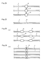
- Fig. 24 shows an enlarged front view of a main portion of a twelfth embodiment of an unit of sealing implement of the present invention
- Fig. 25 shows an enlarged plan view of a main portion of the twelfth embodiment.
- a filament jamming prevention mechanism 29 comprises a circular plate 33 which is provided on at a center or in the vicinity of the center of the filament part 5.
- This circular plate 33 has a diameter which is larger than that of of the filament part 5 and a value of which is set so that each one of the circular plate 33 each adjacently being arranged to each other without contacting with each other in a vertical direction.
- each one of the circular plate 33 are connected with each other with an connecting member 32.
- the filament parts 5 arr prevented from being intermingled with each other when the filament parts 5 is vent and mounted on the shooting gun 18.
- the filament jamming prevention mechanism 29 comprises an oval shaped plate 34 and two of these oval shaped plates 34 are provided on and arranged along the filament part 5 with a prescribed distance interposed therebetween.
- the filament jamming prevention mechanism 29 comprises a triangular or a corn shape type member 35 and two of these shaped plates 35 are provided on and arranged along the filament part 5 with a prescribed distance interoosed therebetween.
- the filament jamming prevention mechanism may comprise a member having a pyramid type configuration and further it may comprise a film like member a flat surface of which faces to a direction which is perpendicular to a direction along which the filament parts are arranged.
- At least two filament jamming prevention mechanisms 29 may be adjacently formed on the filament part or may be formed thereon with a predetermined distance.
- the filament jamming prevention mechanism 29 may be formed on each one of the filament parts 5, respectively, in a zig-zag configuration instead of forming the mechanism on the same portion of each filament part, respectively.
- filament parts which are selected from every second filament part in an arrangement thereof for the unit of single sealing implement.
- the connecting member 32 may be so configured that it can be easily cut off by any one of twisting force, stretching force or shearing force.
- the filament part of the unit of single sealing implements of the present invention may have a circular cross-section or may have a cross-section selected from a flat type configuration, a oval type configuration and a rectangular configuration.
- a size of the socket parts is preferably set at a size with which enabling the handling thereof easily and being externally small.
- One remarkable effect of the present invention is such that it is not required that a flat type unit of single sealing implements should be bent so as to mate with the shooting gun which is specifically designed for shooting each one of the filament part by one by so as to make sealing continuously by actuating an operating lever, when the unit of single sealing implements is to be mounted on the shooting gun, since the unit of single sealing implements had been previously bent, and such mounting operation for the unit of single sealing implements is very easy.
- the unit of single sealing implements can be easily mounted on the gun as it is.
- the unit of single sealing implements can be easily mounted on the shooting gun by bending each one of the filament part having strait linear configuration, easily or if the single sealing implement is used individually for sealing, it is easily attach a label to a commercial good.
- the filament deforming mechanism since the filament deforming mechanism is provided, a processing operation in that such a curvilinear bent portion or folded portion should be formed, becomes easy.
- the filament jamming prevention mechanism is provided in the present invention, such an intermingle of the filament parts will be prevented and thus when the unit of single sealing implements is mounted on the gun, the operation thereof can be implemented smoothly so that an occurrence of the jamming condition can previously be prevented.
- the filament jamming prevention mechanism comprises a film like member
- an aperture of a label can be folded at this film like member so that the label is never moved causing no problem in that a displayed characters on the label cannot be easily observed.
Landscapes
- Engineering & Computer Science (AREA)
- Physics & Mathematics (AREA)
- General Physics & Mathematics (AREA)
- Theoretical Computer Science (AREA)
- Computer Security & Cryptography (AREA)
- Labeling Devices (AREA)
- Package Closures (AREA)
- Vehicle Interior And Exterior Ornaments, Soundproofing, And Insulation (AREA)
- Adhesives Or Adhesive Processes (AREA)
- Sealing Material Composition (AREA)
- Basic Packing Technique (AREA)
- Package Frames And Binding Bands (AREA)
- Glass Compositions (AREA)
- Percussion Or Vibration Massage (AREA)
Applications Claiming Priority (3)
| Application Number | Priority Date | Filing Date | Title |
|---|---|---|---|
| JP11039473A JP2000238714A (ja) | 1999-02-18 | 1999-02-18 | 封緘具 |
| JP3947399 | 1999-02-18 | ||
| PCT/JP2000/000945 WO2000048912A1 (fr) | 1999-02-18 | 2000-02-18 | Dispositif adhesif |
Publications (3)
| Publication Number | Publication Date |
|---|---|
| EP1088762A1 true EP1088762A1 (fr) | 2001-04-04 |
| EP1088762A4 EP1088762A4 (fr) | 2003-01-15 |
| EP1088762B1 EP1088762B1 (fr) | 2004-08-11 |
Family
ID=12554048
Family Applications (1)
| Application Number | Title | Priority Date | Filing Date |
|---|---|---|---|
| EP00904044A Expired - Lifetime EP1088762B1 (fr) | 1999-02-18 | 2000-02-18 | Attache de scellage |
Country Status (6)
| Country | Link |
|---|---|
| US (1) | US6561350B1 (fr) |
| EP (1) | EP1088762B1 (fr) |
| JP (1) | JP2000238714A (fr) |
| AT (1) | ATE273176T1 (fr) |
| DE (1) | DE60012840T2 (fr) |
| WO (1) | WO2000048912A1 (fr) |
Cited By (5)
| Publication number | Priority date | Publication date | Assignee | Title |
|---|---|---|---|---|
| GB2359853A (en) * | 2000-03-02 | 2001-09-05 | Arthur Christopher Lyon | Attachment tags |
| EP1329867A1 (fr) * | 2002-01-18 | 2003-07-23 | Kotec's Co. Ltd. | Elément de fixation |
| WO2014186335A1 (fr) * | 2013-05-14 | 2014-11-20 | Nic Products Inc. | Indicateur d'effraction rotatif |
| US8960737B2 (en) | 2012-04-19 | 2015-02-24 | Nic Products Inc. | Lock bolt |
| US10186176B2 (en) * | 2013-05-14 | 2019-01-22 | Nic Products, Inc. | Rotary security seal |
Families Citing this family (8)
| Publication number | Priority date | Publication date | Assignee | Title |
|---|---|---|---|---|
| ATE253414T1 (de) * | 1999-08-13 | 2003-11-15 | Siemens Ag | Automatisches behälterbehandlungssystem für einen sortierer |
| US7164360B2 (en) * | 2002-08-14 | 2007-01-16 | Mark Schiebler | Multi-use linkage device |
| US6681451B1 (en) * | 2002-08-19 | 2004-01-27 | Adams Mfg. Corp. | Flexible plastic tie |
| USD514425S1 (en) | 2004-05-27 | 2006-02-07 | Brammall, Inc. | Locking device |
| US20060266087A1 (en) * | 2004-11-12 | 2006-11-30 | Hamilton Eric K | Locking device |
| US8926688B2 (en) * | 2008-01-11 | 2015-01-06 | W. L. Gore & Assoc. Inc. | Stent having adjacent elements connected by flexible webs |
| CN109661358B (zh) | 2016-09-26 | 2021-06-25 | 因特利格雷特总部有限责任公司 | 利用梭动件容器递送系统实现物料搬运的系统和方法 |
| JP7639216B1 (ja) | 2024-05-22 | 2025-03-04 | 株式会社コーテックス | 係止片取付装置及びループピン |
Family Cites Families (13)
| Publication number | Priority date | Publication date | Assignee | Title |
|---|---|---|---|---|
| US3516124A (en) * | 1968-04-18 | 1970-06-23 | Dennison Mfg Co | Connector for holding articles together |
| US3712655A (en) * | 1970-11-16 | 1973-01-23 | Stoffel Steel Corp | Plastic seal |
| US3942750A (en) * | 1974-08-13 | 1976-03-09 | Thomas & Betts Corporation | Adjustable clamp |
| US4092765A (en) * | 1976-02-12 | 1978-06-06 | Dennison Manufacturing Company | Miniaturized harnessing device |
| ZA786960B (en) * | 1977-12-15 | 1979-11-28 | L Dore | Improvements in or relating to tags and applicators therefor |
| DE2813484C2 (de) * | 1978-03-29 | 1982-12-30 | United-Carr Gmbh, 6000 Frankfurt | Kabelband |
| JPS581666A (ja) * | 1981-06-26 | 1983-01-07 | 株式会社トスカ | 封緘具 |
| GB2103274B (en) * | 1981-06-26 | 1985-01-30 | Japan Banok Co Ltd | Fastener |
| US4502186A (en) * | 1981-10-20 | 1985-03-05 | Blounthurst Limited | Clip for securing hosepipes and like uses |
| US4730615A (en) * | 1986-03-03 | 1988-03-15 | Pfizer Hospital Products Group, Inc. | Sternum closure device |
| US5333361A (en) * | 1991-12-20 | 1994-08-02 | W. A. Deutsher Pty. Ltd. | Keeper clip |
| JPH10116034A (ja) * | 1996-10-14 | 1998-05-06 | J Ii Kk | タグ吊持用のフレキシブルピン材 |
| JP3390983B2 (ja) * | 1995-05-17 | 2003-03-31 | ジェイ・イー株式会社 | タッグ吊持用ループピン装着具 |
-
1999
- 1999-02-18 JP JP11039473A patent/JP2000238714A/ja active Pending
-
2000
- 2000-02-18 EP EP00904044A patent/EP1088762B1/fr not_active Expired - Lifetime
- 2000-02-18 DE DE60012840T patent/DE60012840T2/de not_active Expired - Fee Related
- 2000-02-18 US US09/673,351 patent/US6561350B1/en not_active Expired - Fee Related
- 2000-02-18 AT AT00904044T patent/ATE273176T1/de not_active IP Right Cessation
- 2000-02-18 WO PCT/JP2000/000945 patent/WO2000048912A1/fr not_active Ceased
Non-Patent Citations (2)
| Title |
|---|
| No further relevant documents disclosed * |
| See also references of WO0048912A1 * |
Cited By (7)
| Publication number | Priority date | Publication date | Assignee | Title |
|---|---|---|---|---|
| GB2359853A (en) * | 2000-03-02 | 2001-09-05 | Arthur Christopher Lyon | Attachment tags |
| EP1329867A1 (fr) * | 2002-01-18 | 2003-07-23 | Kotec's Co. Ltd. | Elément de fixation |
| US6848575B2 (en) | 2002-01-18 | 2005-02-01 | Kotec's Co., Ltd. | Fastening element |
| US8960737B2 (en) | 2012-04-19 | 2015-02-24 | Nic Products Inc. | Lock bolt |
| WO2014186335A1 (fr) * | 2013-05-14 | 2014-11-20 | Nic Products Inc. | Indicateur d'effraction rotatif |
| US9175501B2 (en) | 2013-05-14 | 2015-11-03 | Nic Products, Inc. | Rotary security seal |
| US10186176B2 (en) * | 2013-05-14 | 2019-01-22 | Nic Products, Inc. | Rotary security seal |
Also Published As
| Publication number | Publication date |
|---|---|
| EP1088762B1 (fr) | 2004-08-11 |
| WO2000048912A1 (fr) | 2000-08-24 |
| DE60012840D1 (de) | 2004-09-16 |
| DE60012840T2 (de) | 2004-12-30 |
| US6561350B1 (en) | 2003-05-13 |
| EP1088762A4 (fr) | 2003-01-15 |
| ATE273176T1 (de) | 2004-08-15 |
| JP2000238714A (ja) | 2000-09-05 |
Similar Documents
| Publication | Publication Date | Title |
|---|---|---|
| EP1088762B1 (fr) | Attache de scellage | |
| US6371293B2 (en) | Fastener assembly | |
| AU696535B2 (en) | Needle for use in the rodless dispensing of plastic fasteners | |
| US5799375A (en) | Fastener assembly | |
| GB2270713A (en) | Tag fastener | |
| EP1186550A2 (fr) | Instrument de scellage | |
| EP0915449B1 (fr) | Structure de fixation | |
| EP1329867B1 (fr) | Elément de fixation | |
| US3924298A (en) | Attachment and mounting construction | |
| US4535926A (en) | Fastener dispensing device | |
| US6009997A (en) | Loop fastener, fastener clip including same and loop fastener dispensing tool | |
| EP1489013A1 (fr) | Pistolet de fixation d'épingles en boucle | |
| EP1145965B1 (fr) | Elément de fixation | |
| EP1366994A1 (fr) | Dispositif de pose d'attaches | |
| US6352156B1 (en) | Sealer | |
| EP1083537A2 (fr) | Instrument de scellage | |
| EP0474938A1 (fr) | Ensemble d'attaches et dispositif pour leur utilisation | |
| WO2002016211A1 (fr) | Aiguille destinee a etre utilisee dans un outil distributeur d'attaches en plastique | |
| WO1987004554A1 (fr) | Attache-etiquettes avec connecteurs anti-accrochage | |
| EP1659066A2 (fr) | Dispositif utilisé dans un appareil pour attacher des étiquettes à ficelle | |
| GB2114493A (en) | Fastener attacher |
Legal Events
| Date | Code | Title | Description |
|---|---|---|---|
| PUAI | Public reference made under article 153(3) epc to a published international application that has entered the european phase |
Free format text: ORIGINAL CODE: 0009012 |
|
| AK | Designated contracting states |
Kind code of ref document: A1 Designated state(s): AT BE CH CY DE DK ES FI FR GB GR IE IT LI LU MC NL PT SE |
|
| 17P | Request for examination filed |
Effective date: 20010222 |
|
| A4 | Supplementary search report drawn up and despatched |
Effective date: 20021129 |
|
| AK | Designated contracting states |
Kind code of ref document: A4 Designated state(s): AT BE CH CY DE DK ES FI FR GB GR IE IT LI LU MC NL PT SE |
|
| RIC1 | Information provided on ipc code assigned before grant |
Free format text: 7B 65C 7/00 A, 7G 09F 3/03 B, 7G 09F 3/14 B |
|
| 17Q | First examination report despatched |
Effective date: 20030718 |
|
| GRAP | Despatch of communication of intention to grant a patent |
Free format text: ORIGINAL CODE: EPIDOSNIGR1 |
|
| RTI1 | Title (correction) |
Free format text: SEALING IMPLEMENT |
|
| RTI1 | Title (correction) |
Free format text: SEALING IMPLEMENT |
|
| GRAS | Grant fee paid |
Free format text: ORIGINAL CODE: EPIDOSNIGR3 |
|
| GRAA | (expected) grant |
Free format text: ORIGINAL CODE: 0009210 |
|
| AK | Designated contracting states |
Kind code of ref document: B1 Designated state(s): AT BE CH CY DE DK ES FI FR GB GR IE IT LI LU MC NL PT SE |
|
| PG25 | Lapsed in a contracting state [announced via postgrant information from national office to epo] |
Ref country code: ES Free format text: LAPSE BECAUSE OF FAILURE TO SUBMIT A TRANSLATION OF THE DESCRIPTION OR TO PAY THE FEE WITHIN THE PRESCRIBED TIME-LIMIT Effective date: 20040811 Ref country code: BE Free format text: LAPSE BECAUSE OF FAILURE TO SUBMIT A TRANSLATION OF THE DESCRIPTION OR TO PAY THE FEE WITHIN THE PRESCRIBED TIME-LIMIT Effective date: 20040811 Ref country code: CH Free format text: LAPSE BECAUSE OF FAILURE TO SUBMIT A TRANSLATION OF THE DESCRIPTION OR TO PAY THE FEE WITHIN THE PRESCRIBED TIME-LIMIT Effective date: 20040811 Ref country code: LI Free format text: LAPSE BECAUSE OF FAILURE TO SUBMIT A TRANSLATION OF THE DESCRIPTION OR TO PAY THE FEE WITHIN THE PRESCRIBED TIME-LIMIT Effective date: 20040811 Ref country code: FI Free format text: LAPSE BECAUSE OF FAILURE TO SUBMIT A TRANSLATION OF THE DESCRIPTION OR TO PAY THE FEE WITHIN THE PRESCRIBED TIME-LIMIT Effective date: 20040811 Ref country code: AT Free format text: LAPSE BECAUSE OF FAILURE TO SUBMIT A TRANSLATION OF THE DESCRIPTION OR TO PAY THE FEE WITHIN THE PRESCRIBED TIME-LIMIT Effective date: 20040811 Ref country code: NL Free format text: LAPSE BECAUSE OF FAILURE TO SUBMIT A TRANSLATION OF THE DESCRIPTION OR TO PAY THE FEE WITHIN THE PRESCRIBED TIME-LIMIT Effective date: 20040811 |
|
| REG | Reference to a national code |
Ref country code: GB Ref legal event code: FG4D |
|
| REG | Reference to a national code |
Ref country code: CH Ref legal event code: EP |
|
| REG | Reference to a national code |
Ref country code: IE Ref legal event code: FG4D |
|
| REF | Corresponds to: |
Ref document number: 60012840 Country of ref document: DE Date of ref document: 20040916 Kind code of ref document: P |
|
| PG25 | Lapsed in a contracting state [announced via postgrant information from national office to epo] |
Ref country code: GR Free format text: LAPSE BECAUSE OF FAILURE TO SUBMIT A TRANSLATION OF THE DESCRIPTION OR TO PAY THE FEE WITHIN THE PRESCRIBED TIME-LIMIT Effective date: 20041111 Ref country code: SE Free format text: LAPSE BECAUSE OF FAILURE TO SUBMIT A TRANSLATION OF THE DESCRIPTION OR TO PAY THE FEE WITHIN THE PRESCRIBED TIME-LIMIT Effective date: 20041111 Ref country code: DK Free format text: LAPSE BECAUSE OF FAILURE TO SUBMIT A TRANSLATION OF THE DESCRIPTION OR TO PAY THE FEE WITHIN THE PRESCRIBED TIME-LIMIT Effective date: 20041111 |
|
| NLV1 | Nl: lapsed or annulled due to failure to fulfill the requirements of art. 29p and 29m of the patents act | ||
| REG | Reference to a national code |
Ref country code: CH Ref legal event code: PL |
|
| PG25 | Lapsed in a contracting state [announced via postgrant information from national office to epo] |
Ref country code: IT Free format text: LAPSE BECAUSE OF NON-PAYMENT OF DUE FEES Effective date: 20050218 Ref country code: GB Free format text: LAPSE BECAUSE OF NON-PAYMENT OF DUE FEES Effective date: 20050218 Ref country code: LU Free format text: LAPSE BECAUSE OF NON-PAYMENT OF DUE FEES Effective date: 20050218 Ref country code: CY Free format text: LAPSE BECAUSE OF FAILURE TO SUBMIT A TRANSLATION OF THE DESCRIPTION OR TO PAY THE FEE WITHIN THE PRESCRIBED TIME-LIMIT Effective date: 20050218 |
|
| PG25 | Lapsed in a contracting state [announced via postgrant information from national office to epo] |
Ref country code: MC Free format text: LAPSE BECAUSE OF NON-PAYMENT OF DUE FEES Effective date: 20050228 |
|
| ET | Fr: translation filed | ||
| PLBE | No opposition filed within time limit |
Free format text: ORIGINAL CODE: 0009261 |
|
| STAA | Information on the status of an ep patent application or granted ep patent |
Free format text: STATUS: NO OPPOSITION FILED WITHIN TIME LIMIT |
|
| 26N | No opposition filed |
Effective date: 20050512 |
|
| PG25 | Lapsed in a contracting state [announced via postgrant information from national office to epo] |
Ref country code: DE Free format text: LAPSE BECAUSE OF NON-PAYMENT OF DUE FEES Effective date: 20050901 |
|
| GBPC | Gb: european patent ceased through non-payment of renewal fee |
Effective date: 20050218 |
|
| REG | Reference to a national code |
Ref country code: IE Ref legal event code: MM4A |
|
| PG25 | Lapsed in a contracting state [announced via postgrant information from national office to epo] |
Ref country code: PT Free format text: LAPSE BECAUSE OF NON-PAYMENT OF DUE FEES Effective date: 20050111 |
|
| PG25 | Lapsed in a contracting state [announced via postgrant information from national office to epo] |
Ref country code: FR Free format text: LAPSE BECAUSE OF NON-PAYMENT OF DUE FEES Effective date: 20050228 |
|
| REG | Reference to a national code |
Ref country code: FR Ref legal event code: ST Effective date: 20111021 |