EP1659324A1 - Mitigeur pour robinetterie sanitaire - Google Patents
Mitigeur pour robinetterie sanitaire Download PDFInfo
- Publication number
- EP1659324A1 EP1659324A1 EP05024061A EP05024061A EP1659324A1 EP 1659324 A1 EP1659324 A1 EP 1659324A1 EP 05024061 A EP05024061 A EP 05024061A EP 05024061 A EP05024061 A EP 05024061A EP 1659324 A1 EP1659324 A1 EP 1659324A1
- Authority
- EP
- European Patent Office
- Prior art keywords
- pins
- mixing valve
- valve according
- valve seat
- seat disc
- Prior art date
- Legal status (The legal status is an assumption and is not a legal conclusion. Google has not performed a legal analysis and makes no representation as to the accuracy of the status listed.)
- Granted
Links
- XLYOFNOQVPJJNP-UHFFFAOYSA-N water Substances O XLYOFNOQVPJJNP-UHFFFAOYSA-N 0.000 claims abstract description 26
- 239000000463 material Substances 0.000 claims abstract description 6
- 239000007787 solid Substances 0.000 claims abstract description 4
- 238000003780 insertion Methods 0.000 claims description 2
- 230000037431 insertion Effects 0.000 claims description 2
- 229910010293 ceramic material Inorganic materials 0.000 description 2
- 238000000034 method Methods 0.000 description 2
- 230000000694 effects Effects 0.000 description 1
- 238000001746 injection moulding Methods 0.000 description 1
- 238000004519 manufacturing process Methods 0.000 description 1
- 230000004048 modification Effects 0.000 description 1
- 238000012986 modification Methods 0.000 description 1
- 238000011144 upstream manufacturing Methods 0.000 description 1
Images



Classifications
-
- F—MECHANICAL ENGINEERING; LIGHTING; HEATING; WEAPONS; BLASTING
- F16—ENGINEERING ELEMENTS AND UNITS; GENERAL MEASURES FOR PRODUCING AND MAINTAINING EFFECTIVE FUNCTIONING OF MACHINES OR INSTALLATIONS; THERMAL INSULATION IN GENERAL
- F16K—VALVES; TAPS; COCKS; ACTUATING-FLOATS; DEVICES FOR VENTING OR AERATING
- F16K11/00—Multiple-way valves, e.g. mixing valves; Pipe fittings incorporating such valves
- F16K11/02—Multiple-way valves, e.g. mixing valves; Pipe fittings incorporating such valves with all movable sealing faces moving as one unit
- F16K11/06—Multiple-way valves, e.g. mixing valves; Pipe fittings incorporating such valves with all movable sealing faces moving as one unit comprising only sliding valves, i.e. sliding closure elements
- F16K11/078—Multiple-way valves, e.g. mixing valves; Pipe fittings incorporating such valves with all movable sealing faces moving as one unit comprising only sliding valves, i.e. sliding closure elements with pivoted and linearly movable closure members
- F16K11/0782—Single-lever operated mixing valves with closure members having flat sealing faces
- F16K11/0787—Single-lever operated mixing valves with closure members having flat sealing faces with both the supply and the discharge passages being on the same side of the closure members
-
- F—MECHANICAL ENGINEERING; LIGHTING; HEATING; WEAPONS; BLASTING
- F16—ENGINEERING ELEMENTS AND UNITS; GENERAL MEASURES FOR PRODUCING AND MAINTAINING EFFECTIVE FUNCTIONING OF MACHINES OR INSTALLATIONS; THERMAL INSULATION IN GENERAL
- F16K—VALVES; TAPS; COCKS; ACTUATING-FLOATS; DEVICES FOR VENTING OR AERATING
- F16K47/00—Means in valves for absorbing fluid energy
- F16K47/02—Means in valves for absorbing fluid energy for preventing water-hammer or noise
- F16K47/026—Means in valves for absorbing fluid energy for preventing water-hammer or noise preventing noise in a single handle mixing valve
Definitions
- the invention relates to a low-noise mixing valve for sanitary fittings with at least inlet openings for cold and hot water valve seat and a slidably disposed to the valve seat disc control disc which is provided with at least one formed as a breakthrough passage and their remote from the valve seat front side of a cover and guide disc is held, wherein in the overflow channel in the region of the wall, a body for flow noise reduction is arranged.
- Such a mixing valve is known from German Offenlegungsschrift DE 33 18 888 A1.
- a sheath of mesh provided, wherein the valve seat facing the region of the shell with an obliquely into the overflow provided above the edge.
- the protruding into the overflow channel edge has a relatively good flow noise-reducing effect.
- the protruding edge also acts as a not inconsiderable flow restrictor, which is undesirable.
- such a strainer is relatively expensive to manufacture and problematic when used in an automatic assembly process for creating the mixing valves.
- the invention has for its object to further improve the mixing valve specified in the preamble of claim 1 and in particular form so that the body for flow noise reduction is inexpensive to produce and the maximum flow rate per unit time is not affected by the body as possible.
- the body is a ring member made of solid sheet material, wherein at the valve seat disc facing end face of the ring member at least in the region of the water inlet openings a series of spaced-apart pins is formed, extending to the Area of a sliding surface of the valve seat disc extend.
- the advantages that can be achieved with the invention are, in particular, that the proposed body can be produced simply and cost-effectively for reducing flow noise. Due to the flat design of the device for flow noise reduction almost no throttling occurs even at the maximum flow rate per unit time. In addition, the ring element made of solid sheet material can be easily integrated into an automated assembly process.
- the pins may advantageously be the distance between the pins about 0.5 times to 1.5 times the width of the pins.
- the length of the pins may expediently be dimensioned such that they correspond approximately to 5 times to 9 times their width.
- the pins can have both a square or rectangular or circular or oval cross-sectional area.
- the cross-sectional area of the pins on the wall of the overflow channel facing side is semicircular and rectangular on the opposite side.
- the valve seat disc facing end faces of the pins may be formed flat or spherical rounded.
- the individual pins can have over their entire length an approximately constant cross-sectional area or, starting from the valve seat pane facing end side over the length of the pins steadily in cross section be increasingly trained.
- the pins can also be dimensioned in such a way that, starting from the end face facing the valve seat disk, they increase only continuously in width until they are connected to the ring element.
- the series of flow noise reduction pens is preferably arranged in the region of the water inlet openings for cold water and hot water.
- the row of pins can also be formed circumferentially on the ring member.
- formed in the valve seat disc inlet openings for cold and hot water can be formed as a circular ring cutouts whose width corresponds to about 5 times to 9 times the thickness of the pins for flow noise reduction.
- formed in the valve seat disc inlet openings for cold and hot water can be formed as a circular ring cutouts whose width corresponds to about 5 times to 9 times the thickness of the pins for flow noise reduction.
- radially projecting tabs or else a substantially circumferential collar can be formed on the ring element. The collar or the tabs of the ring element grasp it in the inserted position into a receiving gap between the covering and guide disc and the control disc.
- the ring element, the lobes or the circumferential collar and the flow noise reducing pins are made in one piece from plastic.
- a mixing valve cartridge 1 is shown, which is used as a unit in a sanitary fitting body, not shown in the drawing and in the inserted position with a or more screws on the fitting body is fastened.
- the mixing valve is arranged in a stepped cylindrical cartridge housing 10, which is closed at the end face with the larger diameter of a bottom 11.
- openings for the cold water inlet, the hot water inlet and a further opening for the exiting the mixing valve water are provided in the inserted position associated with corresponding water supply channels in the sanitary fitting body, not shown in the drawing.
- valve seat disc 2 made of hard material, preferably ceramic material, is arranged and held in a stationary manner by the cartridge housing 10.
- the valve seat disc 2 has a ring-shaped water inlet opening 21 for cold water and a ring-shaped water inlet opening 20 for hot water.
- a water outlet opening 22 is also formed in the center of the valve seat disc 2.
- the water inlet openings 20, 21 and the water outlet opening 22 are sealed to the corresponding openings in the bottom 11.
- a finely machined sliding surface 23 is formed on which a control disk 3 of hard material, preferably also of ceramic material, is attached.
- valve seat pane 2 facing Front side of the control disk 3 is also finely machined, the way that the two discs slidably but waterproof to each other.
- an overflow 30 is formed as an opening, as can be seen in particular from Figure 4 of the drawing.
- a cover and guide plate 35 is attached sealed and with the help of pins (not shown in the drawing), which engage in recesses 31 of the control disk 4, positively connected.
- the cover and guide plate 35 is located on the opposite side of a rotatable, but axially fixed in the cartridge housing 10 arranged bushing 12 at.
- a pivot axis 14 is provided perpendicular to the rotational axis 13, on which a lever 15 is pivotally mounted.
- the inner lever arm of the control lever 15 is hinged to the cover and guide plate 35, while the outer lever arm for receiving a handle, not shown in the drawing from the cartridge housing 10 is led out.
- the cover and guide plate 35 is moved radially together with the control disk 3, whereby the total flow rate can be adjusted by the valve.
- the mixing ratio of the incoming cold and hot water or the temperature of the mixed water can be adjusted.
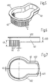
- a ring element 40 is arranged in the overflow channel 30 of the control disk 3, as can be seen in particular from Figure 5 to 7 of the drawing.
- the ring element 40 corresponds with its outer wall to the dimensions of the overflow channel 30.
- a series of pins 4 are formed in a comb-like manner on the ring element 40, the thickness of which corresponds to the thickness 401 of the ring element 40.
- the row of pins extends over an arc of about 180 °, as can be seen from Figure 7 of the drawing.
- the pins 4 have a distance 41 from each other, which corresponds approximately to the width 42 of a pin 4.
- the pins 4 have a length 43 which corresponds approximately to 5 times to 9 times their width 42. In the area of the row of pins 4, the width 400 of the ring element 40 is reduced by about half.
- the pins 4 extend with their end face 44 in the inserted position almost to the sliding surface 23 of the valve seat disc 2 zoom.
- the end face 44 is rounded spherical.
- the wall of the overflow channel 30 facing side of the pins 4 has a semi-circular cross-sectional area, followed by a slightly rectangular cross-sectional area, wherein the rectangular surfaces are directed approximately radially to a center of curvature of the ring member 40.
- a radially outwardly extending collar 402 is formed, which is received in the inserted position of a gap 351 between the cover and guide plate 35 and the control disk 3, as can be seen from Figure 1 of the drawing.
- the ring member 40 with the pins 4 is thus secured axially in the insertion position.
- the ring member 40 with the collar 402 and the pins 4 is integrally made by injection molding of plastic. It has been found that in Wasserzapfvorgang the strongest flow noise occur when the control disk 3 is moved from the shut-off position with the overflow 30 in the overlap with the water inlet openings 20/21.
- the pins 4 cause substantially in this first opening area, the flow noise reduction, which in a surprising way the noise level can be lowered significantly.
- the previously occurring throttle function by the body for flow noise reduction can be substantially avoided with the relatively fine-formed pins.
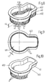
- FIGs 8 and 9 of the drawing a modified embodiment of the body for flow noise reduction is shown.
- the ring element 40 has the same external dimensions, so that it can likewise be inserted into the overflow channel 30, as can be seen in particular from FIG. 4 of the drawing.
- the pins 4 in a circumferential Row arranged.
- the pins 4 have one of the valve seat disc 2 facing rectangular end face, the width of which is about 0.4 mm and the thickness 401 is about 0.5 mm 42.
- the individual pins 4 are trapezoidal in the longitudinal direction and have at the adjoining the ring member 40 end face a width 420 of about 0.55 mm to 0.6 mm.
- the distance 41 of the pins 4 is at the valve seat disc 2 facing end about 0.4 mm and thus corresponds to the width 42 of the pins 4.
- the length 43 of the pins 4 corresponds approximately to the width 400 of the ring member 40. Otherwise, the body corresponds to the flow noise reduction the embodiments shown in Figure 5 to 7 of the drawings.
- the body shown in Figure 10 for flow noise reduction is modified so that the pins 4 are formed circularly rounded at mutually facing end faces, wherein the valve seat disc 2 facing end face 44 forms a circular surface.
- FIG. 13 of the drawing finally, a part of a further modified body for flow noise reduction is shown in view from below.
- the bars 4 in this case have the outer shape of the embodiment shown in Figure 5 to 7. In addition, this is at the of the wall of the overflow. 30 facing away from the side wall of the rods 4 in the region of the rounded end face 44, a circumferential transverse web 45 is integrally formed on the pins 4.
- the cross bar 45 is approximately circular in cross section and has a diameter of 0.3 mm to 0.5 mm.
Landscapes
- Engineering & Computer Science (AREA)
- General Engineering & Computer Science (AREA)
- Mechanical Engineering (AREA)
- Multiple-Way Valves (AREA)
- Details Of Valves (AREA)
- Valve Housings (AREA)
Applications Claiming Priority (1)
| Application Number | Priority Date | Filing Date | Title |
|---|---|---|---|
| DE102004056568A DE102004056568A1 (de) | 2004-11-23 | 2004-11-23 | Mischventil für Sanitärarmaturen |
Publications (2)
| Publication Number | Publication Date |
|---|---|
| EP1659324A1 true EP1659324A1 (fr) | 2006-05-24 |
| EP1659324B1 EP1659324B1 (fr) | 2008-03-19 |
Family
ID=35655526
Family Applications (1)
| Application Number | Title | Priority Date | Filing Date |
|---|---|---|---|
| EP05024061A Expired - Lifetime EP1659324B1 (fr) | 2004-11-23 | 2005-11-04 | Mitigeur pour robinetterie sanitaire |
Country Status (4)
| Country | Link |
|---|---|
| EP (1) | EP1659324B1 (fr) |
| AT (1) | ATE389842T1 (fr) |
| DE (2) | DE102004056568A1 (fr) |
| ES (1) | ES2303660T3 (fr) |
Cited By (1)
| Publication number | Priority date | Publication date | Assignee | Title |
|---|---|---|---|---|
| ITMI20090380A1 (it) * | 2009-03-12 | 2010-09-13 | Piero Cattaneo | Cartuccia provvista di un dispositivo anti colpo di ariete. |
Families Citing this family (3)
| Publication number | Priority date | Publication date | Assignee | Title |
|---|---|---|---|---|
| WO2008135218A1 (fr) | 2007-05-05 | 2008-11-13 | Ideal-Standard International B.V.B.A. | Cartouche de commande pour mitigeur avec un composant d'atténuation acoustique |
| DE102008000107A1 (de) * | 2008-01-21 | 2009-07-23 | Ceramtec Ag | Kartusche für eine Sanitärarmatur |
| DE102008000109A1 (de) | 2008-01-21 | 2009-07-23 | Ceramtec Ag | Kartuschengehäuse |
Citations (7)
| Publication number | Priority date | Publication date | Assignee | Title |
|---|---|---|---|---|
| US4301836A (en) * | 1978-01-26 | 1981-11-24 | Aktiengesellschaft Karrer, Weber & Cie | Hot and cold water sanitary mixing set |
| CH630711A5 (en) * | 1978-06-23 | 1982-06-30 | Karrer Weber & Cie Ag | Control element for sanitary single-lever mixing batteries |
| DE3134280A1 (de) * | 1980-09-05 | 1982-08-12 | K. Oras Oy, 26100 Rauma | Geraeuschdaempfungsvorrichtung fuer ein mischventil |
| DE3202113A1 (de) * | 1981-02-20 | 1982-11-11 | Aktiengesellschaft Karrer, Weber & Cie, 5726 Unterkulm | "mischventil fuer sanitaere einhebel-mischbatterie" |
| DE3318888A1 (de) | 1983-05-25 | 1984-11-29 | Friedrich Grohe Armaturenfabrik Gmbh & Co, 5870 Hemer | Geraeuscharmes ventil fuer sanitaerarmaturen |
| DE8800295U1 (de) * | 1987-01-27 | 1988-04-07 | RAF Rubinetterie S.p.A., San Maurizio d'Opaglio, Novara | Geräuschdämpfer für Hähne, insbesondere für Mischhähne mit keramischen Drosselscheiben |
| EP0311573A1 (fr) * | 1987-09-18 | 1989-04-12 | MAMOLI ROBINETTERIA S.p.A. | Cartouche pour robinetterie mélangeuse avec plaque de fermeture céramique |
-
2004
- 2004-11-23 DE DE102004056568A patent/DE102004056568A1/de not_active Withdrawn
-
2005
- 2005-11-04 EP EP05024061A patent/EP1659324B1/fr not_active Expired - Lifetime
- 2005-11-04 ES ES05024061T patent/ES2303660T3/es not_active Expired - Lifetime
- 2005-11-04 AT AT05024061T patent/ATE389842T1/de not_active IP Right Cessation
- 2005-11-04 DE DE502005003292T patent/DE502005003292D1/de not_active Expired - Lifetime
Patent Citations (7)
| Publication number | Priority date | Publication date | Assignee | Title |
|---|---|---|---|---|
| US4301836A (en) * | 1978-01-26 | 1981-11-24 | Aktiengesellschaft Karrer, Weber & Cie | Hot and cold water sanitary mixing set |
| CH630711A5 (en) * | 1978-06-23 | 1982-06-30 | Karrer Weber & Cie Ag | Control element for sanitary single-lever mixing batteries |
| DE3134280A1 (de) * | 1980-09-05 | 1982-08-12 | K. Oras Oy, 26100 Rauma | Geraeuschdaempfungsvorrichtung fuer ein mischventil |
| DE3202113A1 (de) * | 1981-02-20 | 1982-11-11 | Aktiengesellschaft Karrer, Weber & Cie, 5726 Unterkulm | "mischventil fuer sanitaere einhebel-mischbatterie" |
| DE3318888A1 (de) | 1983-05-25 | 1984-11-29 | Friedrich Grohe Armaturenfabrik Gmbh & Co, 5870 Hemer | Geraeuscharmes ventil fuer sanitaerarmaturen |
| DE8800295U1 (de) * | 1987-01-27 | 1988-04-07 | RAF Rubinetterie S.p.A., San Maurizio d'Opaglio, Novara | Geräuschdämpfer für Hähne, insbesondere für Mischhähne mit keramischen Drosselscheiben |
| EP0311573A1 (fr) * | 1987-09-18 | 1989-04-12 | MAMOLI ROBINETTERIA S.p.A. | Cartouche pour robinetterie mélangeuse avec plaque de fermeture céramique |
Cited By (4)
| Publication number | Priority date | Publication date | Assignee | Title |
|---|---|---|---|---|
| ITMI20090380A1 (it) * | 2009-03-12 | 2010-09-13 | Piero Cattaneo | Cartuccia provvista di un dispositivo anti colpo di ariete. |
| EP2228574A1 (fr) * | 2009-03-12 | 2010-09-15 | Piero Cattaneo | Cartouche avec une méchanisme d'amortissement |
| US20100229985A1 (en) * | 2009-03-12 | 2010-09-16 | Piero Cattaneo | Cartridge including an anti-ram device |
| US8550424B2 (en) * | 2009-03-12 | 2013-10-08 | Piero Cattaneo | Cartridge including an anti-ram device |
Also Published As
| Publication number | Publication date |
|---|---|
| EP1659324B1 (fr) | 2008-03-19 |
| DE502005003292D1 (de) | 2008-04-30 |
| ATE389842T1 (de) | 2008-04-15 |
| ES2303660T3 (es) | 2008-08-16 |
| DE102004056568A1 (de) | 2006-05-24 |
Similar Documents
| Publication | Publication Date | Title |
|---|---|---|
| EP2041375B1 (fr) | Embout de sortie | |
| DE60022787T2 (de) | Mehrwegventil | |
| EP0801255B1 (fr) | Tiroir rotative | |
| EP2497866A2 (fr) | Robinet doté d'une sortie orientable | |
| DE112017000317T5 (de) | Mischeineit, mit diesem verbundenen Wasserhahn mit Mischbatterie und Verfahren zur Herstellung eines derartigen Wasserhahns mit Mischbatterie | |
| EP3748207A1 (fr) | Cartouche de soupape pour une armature sanitaire | |
| EP3021023B1 (fr) | Robinetterie ayant un axe de pivotement decale d'element de commande | |
| AT413882B (de) | Einbauventil für einen heizkörper, insbesondere gliederheizkörper | |
| DE2937475A1 (de) | Einhebel-mischarmatur | |
| EP2584231A2 (fr) | Cartouche de soupape pour un robinet sanitaire | |
| EP1859329B1 (fr) | Regulateur de debit | |
| EP1659324B1 (fr) | Mitigeur pour robinetterie sanitaire | |
| EP1659323B1 (fr) | Vanne pour robinetterie sanitaire | |
| DE112016005186B4 (de) | Thermostatkartusche zum Regeln von zu mischenden warmen und kalten Fluiden | |
| DE3518698A1 (de) | Einhandmischventil | |
| EP1837568A1 (fr) | Valve de levier | |
| DE102019003301A1 (de) | Einhebel-Kartusche für eine Sanitärarmatur | |
| DE2819065C2 (de) | Einhebel-Mischarmatur | |
| DE102004035344B4 (de) | Thermostatventil | |
| DE102006012304B4 (de) | Hebelventil | |
| DE3031380C2 (de) | Drehschieber | |
| EP1647747B1 (fr) | Robinet mitigeur | |
| DE9304346U1 (de) | Heizkörperanordnung | |
| DE19634936A1 (de) | Düsenauslaß | |
| DE102005020990B4 (de) | Ventil mit einsetzbarer Durchflussmengenbegrenzung |
Legal Events
| Date | Code | Title | Description |
|---|---|---|---|
| PUAI | Public reference made under article 153(3) epc to a published international application that has entered the european phase |
Free format text: ORIGINAL CODE: 0009012 |
|
| AK | Designated contracting states |
Kind code of ref document: A1 Designated state(s): AT BE BG CH CY CZ DE DK EE ES FI FR GB GR HU IE IS IT LI LT LU LV MC NL PL PT RO SE SI SK TR |
|
| AX | Request for extension of the european patent |
Extension state: AL BA HR MK YU |
|
| RAP1 | Party data changed (applicant data changed or rights of an application transferred) |
Owner name: GROHE AG |
|
| 17P | Request for examination filed |
Effective date: 20061117 |
|
| AKX | Designation fees paid |
Designated state(s): AT BE BG CH CY CZ DE DK EE ES FI FR GB GR HU IE IS IT LI LT LU LV MC NL PL PT RO SE SI SK TR |
|
| 17Q | First examination report despatched |
Effective date: 20070521 |
|
| GRAP | Despatch of communication of intention to grant a patent |
Free format text: ORIGINAL CODE: EPIDOSNIGR1 |
|
| GRAS | Grant fee paid |
Free format text: ORIGINAL CODE: EPIDOSNIGR3 |
|
| GRAA | (expected) grant |
Free format text: ORIGINAL CODE: 0009210 |
|
| AK | Designated contracting states |
Kind code of ref document: B1 Designated state(s): AT BE BG CH CY CZ DE DK EE ES FI FR GB GR HU IE IS IT LI LT LU LV MC NL PL PT RO SE SI SK TR |
|
| REG | Reference to a national code |
Ref country code: GB Ref legal event code: FG4D Free format text: NOT ENGLISH |
|
| REG | Reference to a national code |
Ref country code: CH Ref legal event code: EP |
|
| REF | Corresponds to: |
Ref document number: 502005003292 Country of ref document: DE Date of ref document: 20080430 Kind code of ref document: P |
|
| REG | Reference to a national code |
Ref country code: IE Ref legal event code: FG4D Free format text: LANGUAGE OF EP DOCUMENT: GERMAN |
|
| PG25 | Lapsed in a contracting state [announced via postgrant information from national office to epo] |
Ref country code: FI Free format text: LAPSE BECAUSE OF FAILURE TO SUBMIT A TRANSLATION OF THE DESCRIPTION OR TO PAY THE FEE WITHIN THE PRESCRIBED TIME-LIMIT Effective date: 20080319 Ref country code: LT Free format text: LAPSE BECAUSE OF FAILURE TO SUBMIT A TRANSLATION OF THE DESCRIPTION OR TO PAY THE FEE WITHIN THE PRESCRIBED TIME-LIMIT Effective date: 20080319 |
|
| REG | Reference to a national code |
Ref country code: ES Ref legal event code: FG2A Ref document number: 2303660 Country of ref document: ES Kind code of ref document: T3 |
|
| NLV1 | Nl: lapsed or annulled due to failure to fulfill the requirements of art. 29p and 29m of the patents act | ||
| PG25 | Lapsed in a contracting state [announced via postgrant information from national office to epo] |
Ref country code: SI Free format text: LAPSE BECAUSE OF FAILURE TO SUBMIT A TRANSLATION OF THE DESCRIPTION OR TO PAY THE FEE WITHIN THE PRESCRIBED TIME-LIMIT Effective date: 20080319 Ref country code: PL Free format text: LAPSE BECAUSE OF FAILURE TO SUBMIT A TRANSLATION OF THE DESCRIPTION OR TO PAY THE FEE WITHIN THE PRESCRIBED TIME-LIMIT Effective date: 20080319 Ref country code: LV Free format text: LAPSE BECAUSE OF FAILURE TO SUBMIT A TRANSLATION OF THE DESCRIPTION OR TO PAY THE FEE WITHIN THE PRESCRIBED TIME-LIMIT Effective date: 20080319 |
|
| REG | Reference to a national code |
Ref country code: IE Ref legal event code: FD4D |
|
| PG25 | Lapsed in a contracting state [announced via postgrant information from national office to epo] |
Ref country code: PT Free format text: LAPSE BECAUSE OF FAILURE TO SUBMIT A TRANSLATION OF THE DESCRIPTION OR TO PAY THE FEE WITHIN THE PRESCRIBED TIME-LIMIT Effective date: 20080826 Ref country code: SE Free format text: LAPSE BECAUSE OF FAILURE TO SUBMIT A TRANSLATION OF THE DESCRIPTION OR TO PAY THE FEE WITHIN THE PRESCRIBED TIME-LIMIT Effective date: 20080619 Ref country code: SK Free format text: LAPSE BECAUSE OF FAILURE TO SUBMIT A TRANSLATION OF THE DESCRIPTION OR TO PAY THE FEE WITHIN THE PRESCRIBED TIME-LIMIT Effective date: 20080319 Ref country code: CZ Free format text: LAPSE BECAUSE OF FAILURE TO SUBMIT A TRANSLATION OF THE DESCRIPTION OR TO PAY THE FEE WITHIN THE PRESCRIBED TIME-LIMIT Effective date: 20080319 |
|
| PG25 | Lapsed in a contracting state [announced via postgrant information from national office to epo] |
Ref country code: NL Free format text: LAPSE BECAUSE OF FAILURE TO SUBMIT A TRANSLATION OF THE DESCRIPTION OR TO PAY THE FEE WITHIN THE PRESCRIBED TIME-LIMIT Effective date: 20080319 Ref country code: RO Free format text: LAPSE BECAUSE OF FAILURE TO SUBMIT A TRANSLATION OF THE DESCRIPTION OR TO PAY THE FEE WITHIN THE PRESCRIBED TIME-LIMIT Effective date: 20080319 |
|
| PG25 | Lapsed in a contracting state [announced via postgrant information from national office to epo] |
Ref country code: IS Free format text: LAPSE BECAUSE OF FAILURE TO SUBMIT A TRANSLATION OF THE DESCRIPTION OR TO PAY THE FEE WITHIN THE PRESCRIBED TIME-LIMIT Effective date: 20080719 |
|
| ET | Fr: translation filed | ||
| PLBE | No opposition filed within time limit |
Free format text: ORIGINAL CODE: 0009261 |
|
| STAA | Information on the status of an ep patent application or granted ep patent |
Free format text: STATUS: NO OPPOSITION FILED WITHIN TIME LIMIT |
|
| PG25 | Lapsed in a contracting state [announced via postgrant information from national office to epo] |
Ref country code: DK Free format text: LAPSE BECAUSE OF FAILURE TO SUBMIT A TRANSLATION OF THE DESCRIPTION OR TO PAY THE FEE WITHIN THE PRESCRIBED TIME-LIMIT Effective date: 20080319 Ref country code: IE Free format text: LAPSE BECAUSE OF FAILURE TO SUBMIT A TRANSLATION OF THE DESCRIPTION OR TO PAY THE FEE WITHIN THE PRESCRIBED TIME-LIMIT Effective date: 20080319 |
|
| 26N | No opposition filed |
Effective date: 20081222 |
|
| REG | Reference to a national code |
Ref country code: HU Ref legal event code: AG4A Ref document number: E004387 Country of ref document: HU |
|
| PG25 | Lapsed in a contracting state [announced via postgrant information from national office to epo] |
Ref country code: EE Free format text: LAPSE BECAUSE OF FAILURE TO SUBMIT A TRANSLATION OF THE DESCRIPTION OR TO PAY THE FEE WITHIN THE PRESCRIBED TIME-LIMIT Effective date: 20080319 Ref country code: BG Free format text: LAPSE BECAUSE OF FAILURE TO SUBMIT A TRANSLATION OF THE DESCRIPTION OR TO PAY THE FEE WITHIN THE PRESCRIBED TIME-LIMIT Effective date: 20080619 |
|
| PGFP | Annual fee paid to national office [announced via postgrant information from national office to epo] |
Ref country code: FR Payment date: 20081113 Year of fee payment: 4 |
|
| BERE | Be: lapsed |
Owner name: GROHE A.G. Effective date: 20081130 |
|
| PG25 | Lapsed in a contracting state [announced via postgrant information from national office to epo] |
Ref country code: MC Free format text: LAPSE BECAUSE OF NON-PAYMENT OF DUE FEES Effective date: 20081130 |
|
| PG25 | Lapsed in a contracting state [announced via postgrant information from national office to epo] |
Ref country code: BE Free format text: LAPSE BECAUSE OF NON-PAYMENT OF DUE FEES Effective date: 20081130 Ref country code: CY Free format text: LAPSE BECAUSE OF FAILURE TO SUBMIT A TRANSLATION OF THE DESCRIPTION OR TO PAY THE FEE WITHIN THE PRESCRIBED TIME-LIMIT Effective date: 20080319 |
|
| PG25 | Lapsed in a contracting state [announced via postgrant information from national office to epo] |
Ref country code: AT Free format text: LAPSE BECAUSE OF NON-PAYMENT OF DUE FEES Effective date: 20081104 |
|
| REG | Reference to a national code |
Ref country code: CH Ref legal event code: PL |
|
| GBPC | Gb: european patent ceased through non-payment of renewal fee |
Effective date: 20091104 |
|
| PG25 | Lapsed in a contracting state [announced via postgrant information from national office to epo] |
Ref country code: LU Free format text: LAPSE BECAUSE OF NON-PAYMENT OF DUE FEES Effective date: 20081104 |
|
| REG | Reference to a national code |
Ref country code: FR Ref legal event code: ST Effective date: 20100730 |
|
| PG25 | Lapsed in a contracting state [announced via postgrant information from national office to epo] |
Ref country code: TR Free format text: LAPSE BECAUSE OF FAILURE TO SUBMIT A TRANSLATION OF THE DESCRIPTION OR TO PAY THE FEE WITHIN THE PRESCRIBED TIME-LIMIT Effective date: 20080319 |
|
| PG25 | Lapsed in a contracting state [announced via postgrant information from national office to epo] |
Ref country code: CH Free format text: LAPSE BECAUSE OF NON-PAYMENT OF DUE FEES Effective date: 20091130 Ref country code: FR Free format text: LAPSE BECAUSE OF NON-PAYMENT OF DUE FEES Effective date: 20091130 Ref country code: LI Free format text: LAPSE BECAUSE OF NON-PAYMENT OF DUE FEES Effective date: 20091130 Ref country code: GR Free format text: LAPSE BECAUSE OF FAILURE TO SUBMIT A TRANSLATION OF THE DESCRIPTION OR TO PAY THE FEE WITHIN THE PRESCRIBED TIME-LIMIT Effective date: 20080620 |
|
| PG25 | Lapsed in a contracting state [announced via postgrant information from national office to epo] |
Ref country code: GB Free format text: LAPSE BECAUSE OF NON-PAYMENT OF DUE FEES Effective date: 20091104 |
|
| PGFP | Annual fee paid to national office [announced via postgrant information from national office to epo] |
Ref country code: DE Payment date: 20101119 Year of fee payment: 6 Ref country code: HU Payment date: 20101202 Year of fee payment: 6 |
|
| PGFP | Annual fee paid to national office [announced via postgrant information from national office to epo] |
Ref country code: IT Payment date: 20101125 Year of fee payment: 6 |
|
| PGFP | Annual fee paid to national office [announced via postgrant information from national office to epo] |
Ref country code: ES Payment date: 20101124 Year of fee payment: 6 |
|
| PG25 | Lapsed in a contracting state [announced via postgrant information from national office to epo] |
Ref country code: HU Free format text: LAPSE BECAUSE OF NON-PAYMENT OF DUE FEES Effective date: 20111105 |
|
| PG25 | Lapsed in a contracting state [announced via postgrant information from national office to epo] |
Ref country code: IT Free format text: LAPSE BECAUSE OF NON-PAYMENT OF DUE FEES Effective date: 20111104 |
|
| REG | Reference to a national code |
Ref country code: DE Ref legal event code: R119 Ref document number: 502005003292 Country of ref document: DE Effective date: 20120601 |
|
| REG | Reference to a national code |
Ref country code: ES Ref legal event code: FD2A Effective date: 20130603 |
|
| PG25 | Lapsed in a contracting state [announced via postgrant information from national office to epo] |
Ref country code: DE Free format text: LAPSE BECAUSE OF NON-PAYMENT OF DUE FEES Effective date: 20120601 |
|
| PG25 | Lapsed in a contracting state [announced via postgrant information from national office to epo] |
Ref country code: ES Free format text: LAPSE BECAUSE OF NON-PAYMENT OF DUE FEES Effective date: 20111105 |