EP1659456A2 - Cartouche pour appareil de formation d' images - Google Patents
Cartouche pour appareil de formation d' images Download PDFInfo
- Publication number
- EP1659456A2 EP1659456A2 EP05024542A EP05024542A EP1659456A2 EP 1659456 A2 EP1659456 A2 EP 1659456A2 EP 05024542 A EP05024542 A EP 05024542A EP 05024542 A EP05024542 A EP 05024542A EP 1659456 A2 EP1659456 A2 EP 1659456A2
- Authority
- EP
- European Patent Office
- Prior art keywords
- shutter
- toner
- cartridge
- image forming
- forming apparatus
- Prior art date
- Legal status (The legal status is an assumption and is not a legal conclusion. Google has not performed a legal analysis and makes no representation as to the accuracy of the status listed.)
- Granted
Links
- 238000007599 discharging Methods 0.000 claims description 6
- 238000011161 development Methods 0.000 claims description 3
- 238000000034 method Methods 0.000 abstract description 40
- 239000002699 waste material Substances 0.000 description 52
- 238000012546 transfer Methods 0.000 description 26
- 238000004140 cleaning Methods 0.000 description 12
- 239000000463 material Substances 0.000 description 6
- 239000003086 colorant Substances 0.000 description 4
- 230000005540 biological transmission Effects 0.000 description 3
- 238000004891 communication Methods 0.000 description 3
- 238000010586 diagram Methods 0.000 description 2
- 230000000694 effects Effects 0.000 description 2
- 229920006311 Urethane elastomer Polymers 0.000 description 1
- 230000006978 adaptation Effects 0.000 description 1
- XAGFODPZIPBFFR-UHFFFAOYSA-N aluminium Chemical compound [Al] XAGFODPZIPBFFR-UHFFFAOYSA-N 0.000 description 1
- 229910052782 aluminium Inorganic materials 0.000 description 1
- 210000000078 claw Anatomy 0.000 description 1
- 238000012790 confirmation Methods 0.000 description 1
- 238000012937 correction Methods 0.000 description 1
- 238000005516 engineering process Methods 0.000 description 1
- 238000010438 heat treatment Methods 0.000 description 1
Images






Classifications
-
- G—PHYSICS
- G03—PHOTOGRAPHY; CINEMATOGRAPHY; ANALOGOUS TECHNIQUES USING WAVES OTHER THAN OPTICAL WAVES; ELECTROGRAPHY; HOLOGRAPHY
- G03G—ELECTROGRAPHY; ELECTROPHOTOGRAPHY; MAGNETOGRAPHY
- G03G15/00—Apparatus for electrographic processes using a charge pattern
- G03G15/06—Apparatus for electrographic processes using a charge pattern for developing
-
- G—PHYSICS
- G03—PHOTOGRAPHY; CINEMATOGRAPHY; ANALOGOUS TECHNIQUES USING WAVES OTHER THAN OPTICAL WAVES; ELECTROGRAPHY; HOLOGRAPHY
- G03G—ELECTROGRAPHY; ELECTROPHOTOGRAPHY; MAGNETOGRAPHY
- G03G21/00—Arrangements not provided for by groups G03G13/00 - G03G19/00, e.g. cleaning, elimination of residual charge
- G03G21/10—Collecting or recycling waste developer
- G03G21/12—Toner waste containers
-
- G—PHYSICS
- G03—PHOTOGRAPHY; CINEMATOGRAPHY; ANALOGOUS TECHNIQUES USING WAVES OTHER THAN OPTICAL WAVES; ELECTROGRAPHY; HOLOGRAPHY
- G03G—ELECTROGRAPHY; ELECTROPHOTOGRAPHY; MAGNETOGRAPHY
- G03G15/00—Apparatus for electrographic processes using a charge pattern
- G03G15/06—Apparatus for electrographic processes using a charge pattern for developing
- G03G15/08—Apparatus for electrographic processes using a charge pattern for developing using a solid developer, e.g. powder developer
- G03G15/0822—Arrangements for preparing, mixing, supplying or dispensing developer
- G03G15/0848—Arrangements for testing or measuring developer properties or quality, e.g. charge, size, flowability
- G03G15/0849—Detection or control means for the developer concentration
- G03G15/0855—Detection or control means for the developer concentration the concentration being measured by optical means
-
- G—PHYSICS
- G03—PHOTOGRAPHY; CINEMATOGRAPHY; ANALOGOUS TECHNIQUES USING WAVES OTHER THAN OPTICAL WAVES; ELECTROGRAPHY; HOLOGRAPHY
- G03G—ELECTROGRAPHY; ELECTROPHOTOGRAPHY; MAGNETOGRAPHY
- G03G15/00—Apparatus for electrographic processes using a charge pattern
- G03G15/06—Apparatus for electrographic processes using a charge pattern for developing
- G03G15/08—Apparatus for electrographic processes using a charge pattern for developing using a solid developer, e.g. powder developer
- G03G15/0822—Arrangements for preparing, mixing, supplying or dispensing developer
- G03G15/0865—Arrangements for supplying new developer
-
- G—PHYSICS
- G03—PHOTOGRAPHY; CINEMATOGRAPHY; ANALOGOUS TECHNIQUES USING WAVES OTHER THAN OPTICAL WAVES; ELECTROGRAPHY; HOLOGRAPHY
- G03G—ELECTROGRAPHY; ELECTROPHOTOGRAPHY; MAGNETOGRAPHY
- G03G15/00—Apparatus for electrographic processes using a charge pattern
- G03G15/06—Apparatus for electrographic processes using a charge pattern for developing
- G03G15/08—Apparatus for electrographic processes using a charge pattern for developing using a solid developer, e.g. powder developer
- G03G15/0822—Arrangements for preparing, mixing, supplying or dispensing developer
- G03G15/0877—Arrangements for metering and dispensing developer from a developer cartridge into the development unit
- G03G15/0881—Sealing of developer cartridges
- G03G15/0886—Sealing of developer cartridges by mechanical means, e.g. shutter, plug
-
- G—PHYSICS
- G03—PHOTOGRAPHY; CINEMATOGRAPHY; ANALOGOUS TECHNIQUES USING WAVES OTHER THAN OPTICAL WAVES; ELECTROGRAPHY; HOLOGRAPHY
- G03G—ELECTROGRAPHY; ELECTROPHOTOGRAPHY; MAGNETOGRAPHY
- G03G21/00—Arrangements not provided for by groups G03G13/00 - G03G19/00, e.g. cleaning, elimination of residual charge
- G03G21/10—Collecting or recycling waste developer
- G03G21/105—Arrangements for conveying toner waste
-
- G—PHYSICS
- G03—PHOTOGRAPHY; CINEMATOGRAPHY; ANALOGOUS TECHNIQUES USING WAVES OTHER THAN OPTICAL WAVES; ELECTROGRAPHY; HOLOGRAPHY
- G03G—ELECTROGRAPHY; ELECTROPHOTOGRAPHY; MAGNETOGRAPHY
- G03G2215/00—Apparatus for electrophotographic processes
- G03G2215/06—Developing structures, details
- G03G2215/066—Toner cartridge or other attachable and detachable container for supplying developer material to replace the used material
- G03G2215/0663—Toner cartridge or other attachable and detachable container for supplying developer material to replace the used material having a longitudinal rotational axis, around which at least one part is rotated when mounting or using the cartridge
- G03G2215/0665—Generally horizontally mounting of said toner cartridge parallel to its longitudinal rotational axis
- G03G2215/067—Toner discharging opening covered by arcuate shutter
-
- G—PHYSICS
- G03—PHOTOGRAPHY; CINEMATOGRAPHY; ANALOGOUS TECHNIQUES USING WAVES OTHER THAN OPTICAL WAVES; ELECTROGRAPHY; HOLOGRAPHY
- G03G—ELECTROGRAPHY; ELECTROPHOTOGRAPHY; MAGNETOGRAPHY
- G03G2221/00—Processes not provided for by group G03G2215/00, e.g. cleaning or residual charge elimination
- G03G2221/16—Mechanical means for facilitating the maintenance of the apparatus, e.g. modular arrangements and complete machine concepts
- G03G2221/1651—Mechanical means for facilitating the maintenance of the apparatus, e.g. modular arrangements and complete machine concepts for connecting the different parts
- G03G2221/1654—Locks and means for positioning or alignment
Definitions
- the present invention relates to a cartridge detachably mounted to image forming apparatuses, such as photocopiers and printers of forming images onto recording material by utilizing an electrophotographic system.
- an image forming apparatuses adopting an electrophotographic system that is provided with a cartridge detachably mounted to the image forming apparatus derived by unitizing a plurality of members.
- a cartridge that removes toner still remaining on a photosensitive member or a transfer belt due to failure in complete consumption for tansfer from a photosensitive member or recording material onto a transfer belt to discharge it as waste toner.
- the main body apparatus comprises a housing container of housing waste toner discharged from this cartridge and waste toner carrying means in order to retrieve (or recover) it to the housing container.
- shutter means is essential for the cartridge system detachably mounted to the main body apparatus in order to prevent toner leakage from the cartridge at the time of cartridge replacement (see, for example, Japanese Utility Model Application Laid-Open No. H04-81172).
- a waste toner shutter in a prior art cartridge in the attach/detach system has presented problems as described below. That is, when a cartridge is detached from/attached to the main body apparatus, a user might touch by mistake the waste toner shutter provided to the cartridge, and then the toner shutter would open to leak toner from the waste toner from a discharge port. In addition, such a problem was present that toner would be stuck (or attracted) onto the surface of the cartridge by the toner leaking from the waste toner receiving port provided in the main body side when the cartridge was mounted onto the main body of the image forming apparatus.
- an object of the present invention is to prevent toner from being scattered due to a user's opening, by mistake, a shutter of toner discharge port of a cartridge when he/she exchanges the cartridge.
- Another object of the present invention is to prevent the surface of the cartridge container from being polluted with toner at the time when the waste toner shutter is opened and closed.
- Another object of the present invention is to provide a cartridge that enables miniaturization.
- a cartridge has: a cartridge detachably mounted to an image forming apparatus is provided which comprises: removing means of removing toner on an image bearing member; a discharge port of discharging toner removed by said removing means; a shutter of opening and closing said discharge port; and a lock mechanism of unlockably locking said shutter.
- Another cartridge of the present invention is a cartridge detachably mounted to an image forming apparatus having a shutter of opening and closing a toner receiving port, comprising: removing means of removing toner on an image bearing member; a discharge port of discharging toner removed by said removing means; a shutter of opening and closing said discharge port; and an engaging part engaged with said shutter of said image forming apparatus so that said shutter of said cartridge and said shutter of said image forming apparatus move in conjunction.
- Another cartridge of the present invention is a cartridge detachably mounted to an image forming apparatus, comprising: a toner supply port of receiving toner supply; developing means of developing a latent image formed onto an image bearing member with toner supplied from said toner supply port; removing means of removing toner on an image bearing member; a discharge port of discharging toner removed by said removing means; a first shutter of opening and closing said discharge port; a second shutter of opening and closing said toner supply port; and an engaging part, provided in said image forming apparatus, to be engaged with opening/closing means of opening and closing said first and second shutters at a time when mounting of said cartridge onto said image forming apparatus is completed.
- Another cartridge of the present invention is a cartridge detachably mounted to an image forming apparatus comprising: developing means of developing an electrostatic image formed onto an image bearing member with toner; and removing means of removing toner on an image bearing member, wherein said developing means implements development with toner supplied from outside said cartridge, and toner removed by said removing means is discharged outside said cartridge.
- the present configuration is provided with a plurality of photosensitive drums arranged in a line corresponding with respective colors as an image forming apparatus in an electrophotographic system in a plurality of colors or in full color. And it is a so-called in-line type image forming apparatus that sequentially overlapping toner images in respective colors formed on respective photosensitive drums to form a color image.
- FIG. 1 is a sectional view of the present configuration.
- image forming four process cartridges 114C disposed on a substantial horizontal straight line in a constant distance are provided, and respective images in yellow color, magenta color, cyangens color and black color are formed.
- drum type electrophotographic photosensitive members (hereinafter to be referred to as a photosensitive drum) 115C are installed.
- a primary charging apparatus 116C In the circumference of a photosensitive drums 115C, a primary charging apparatus 116C, a developing apparatus 117C, a transfer roller 118 as transfer means and a drum cleaner apparatus 119C are disposed.
- a laser exposure apparatus 111C is installed below and between the primary charging apparatus 116C and the developing means 117C.
- the photosensitive drum 115C has a photoconductive layer on the drum base member being a negatively charged OPC photoconductive member and made of aluminum and is driven to rotate at a predetermined process speed with a driving apparatus (not shown in the drawing).
- the primary charging apparatus 116C as the primary charging means uniformly charges the surface of the photosensitive drum 115C to a predetermined negative potential by means of a charging bias applied from a charging bias power supply (not shown in the drawing).
- the developing apparatus 117C retains toner internally and causes toner in respective colors to be stuck onto respective electrostatic latent images formed on respective photosensitive drums 115C to be developed (visualized) as toner images.
- the transfer roller 118C shown in FIG. 1 as the primary transfer means is disposed inside an intermediate transfer belt unit 120C and is disposed so as to be urged toward the photosensitive drum 114C.
- the drum cleaner apparatus 119C has a cleaning blade etc. for removing, on the photosensitive drum 114C, transfer residual toner remaining after the primary transfer on the photosensitive drum 115C.
- the intermediate transfer belt unit 120C comprises a drive roller 121C to simultaneously operate as a secondary transfer opposite roller, a gear on the drive roller shaft, that is not shown in the drawing, and is driven to rotate by a drive gear on the main body that is not shown in the drawing either.
- the drive roller 121C is disposed so as to face the secondary transfer roller 122C.
- a fixing apparatus having a fixing roller 123C and a pressure roller 124C is installed in a vertical path configuration.
- the exposure apparatus 111C is configured by laser emitting means of implementing emission corresponding with chronological electric digital pixel signals in given image information, a polygon mirror and a reflection mirror etc.
- the toner image formed with such an image forming apparatus is transferred onto the transfer material T in a secondary transfer part 127C subject to application of resist correction to the transfer material T, which is separated into a single sheet with the sheet feeding roller 125C inside a sheet feeding apparatus 129C with a resist roller 126C.
- the transfer material T undergoes heating/pressing with the fixing apparatus and discharged from the paper output roller 128C.
- toner supplied from the toner cartridge 136C is supplied to the process cartridge 114C in a predetermined amount with quantitatively supplying (or replenishment) means 137C.
- two carrying screws (138C and 139C) in a developing chamber 117C agitate toner and supply (or replenish) the toner to the photosensitive drum 115C from the developing sleeve 140C.
- the toner on the photosensitive drum 115C is transferred onto the intermediate transfer belt.
- a drum cleaning apparatus 119C is provided so as to be located adjacent to the photosensitive drum 115C and a belt cleaning apparatus 130C is provided so as to be located adjacent to the transfer belt respectively.
- the drum cleaning apparatus 119C the one configured by bringing a cleaning blade 131C made of a resilient member such as urethane rubber as removing means into contact with the surface of the photosensitive drum 114C to remove the residual toner is simple in configuration as well as compact and is excellent in toner removing function, and therefore has been widely used conventionally. This configuration comprising this blade is likewise in the belt cleaning means.
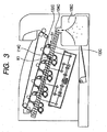
- the waste toner retrieved by the drum cleaning apparatus 119C through such an image forming process is carried to outside the cleaning apparatus, that is, outside the process cartridge 114C with the first carrying screw 132C as in FIG. 3, and is delivered as waste toner to the waste toner carrying apparatus 133C in the main body side of the apparatus at R1.
- the waste toner carrying apparatus 133C refers to a carrying path of carrying waste toner discharged from the belt cleaner apparatus 130 C as well as four drum cleaner apparatuses 119C to the right direction of the main body of the apparatus, and the second carrying screw 134C is disposed rotatably inside the waste toner carrying apparatus and is driven to rotate in the ⁇ K1 direction.
- a waste toner housing apparatus 135C is disposed at the end part at the tip in the carrying direction of the waste toner carrying apparatus 133C and is configured so as to retrieve all the waste toner to its inside.
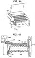
- FIGS. 5A and 5B are perspective views of the process cartridge, wherein a waste toner shutter mechanism 140C as opening/closing means to open and close the delivery part of delivering toner and a supply shutter mechanism 141C are disposed.
- the waste toner shutter mechanism is configured as in FIGS. 6A and 6B to stop the discharge port shutter 102C as an opening/closing member from rotating in the K2 direction and to be capable of no rotation in the K3 direction with a protrusion 143C provided in an enclosure. Therefore, if a user tries to rotate the first shutter by mistake, no rotation occurs, and therefore an orifice J1 (toner discharge port) of the process cartridge 114C and an orifice J2 of the discharge port shutter 102C will not be connected.
- a claw 144C provided in the discharge port shutter 102C is engaged with the protrusion 145C of the cartridge enclosure so that the discharge port shutter 102C will not be removed in the K4 direction either but is a reliable shutter lock configuration.
- FIG. 7A shows a process cartridge 114C prior to setting to the main body apparatus, wherein the discharge port shutter 102C and the supply shutter 147C for supplying toner are locked at the portions Q1 and Q2.
- This process cartridge 114C is set to the main body (is disposed (mounted onto) in a predetermined location to face without relative movement to face the toner delivery part (toner delivery port) J4 in which the toner discharge port is provided corresponding with the main body of the apparatus), and then as in FIG. 7B, the main body frame 146C and the shutter lock member 142C are brought into contact at the portion Q3 so that the shutter lock member 142C moves in the K5 direction and the lock at the portion Q1 is unlocked.
- the toner supply port (not shown in the drawing) of the supply container in the side of the main body of supplying toner to the cartridge and the toner supply receiving port (not shown in the drawing) of the cartridge are disposed (mounted) in a predetermined location to face without relative movement, and then a shutter lock member 149C of locking opening and closing operations of the shutter of the toner supply port will contact the unlocking member 148C provided in the main body to move in the K6 direction to unlock the lock in the portion Q2.
- This will enable the discharge port shutter 102C and the supply shutter 147C to open and close, to transmit drive of moving the shutter as in FIG. 7C to enable thereby the discharge port shutter 102C in the K7 direction to enable the supply shutter 147C to move in the K8 direction to enable connection to the orifice in the main body side.
- the configuration brings the shutter provided in the discharge port of the cartridge into engagement with the shutter provided in the toner receiving port side in the main body side when the cartridge is mounted to the main body of the apparatus and causes the shutter provided in the main body side to receive the drive of the main body to open the shutter of the cartridge.
- the configuration brings the shutter of the toner supply port in the main body side and the shutter of the supply receiving port of the cartridge into engagement to cause the shutter provided in the main body side to receive the drive of the main body to open thereby the shutter of the cartridge.
- the cartridge supply receiving port and the discharge port are provided in the same side in a longitudinal direction of the cartridge so as to limit disposition of the drive source to only one side of the main body of the apparatus to simplify the configuration to make it possible to plan cost reduction.
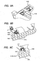
- Such unlocking of a lock can be implemented by opening the first door 020C and the exchange door 030C to the main body apparatus 010A in the K10 and K11 directions, and moving the process cartridge 114C in the K9 direction to be set to the main body apparatus 010C.
- the process cartridge 114C set to the main body apparatus 010C in FIG. 9A comprises a protrusion 150C of the discharge port shutter 102C in the side of the process cartridge 114C as in FIG. 9B and the cavity 151 (fitting part or engaging part) provided in the main body shutter 104C in the main body apparatus side are brought into fitting (engagement) to enable the discharge port shutter 102C and the main body shutter 104C to rotate integrally.
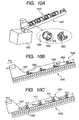
- drive means 152C of moving this shutter is provided with a manual drive on the waste toner carrying apparatus 133C as in FIGS. 10A to 10C, a movement of an opening/closing lever 154C in the ⁇ K13 direction for the gears 153C in connection with the main body shutter 104C in the main body side is configured to cause the rack teeth 155C as a drive transmission part provided in the opening/closing lever as in FIG. 10C to rotate the main body shutter 104C in the K12 direction via the gears 153C.
- movement in the K14 direction is configured to rotate it in the opposite direction.
- the above described case relates to a configuration for the shutter to rotate, but as in FIGS. 11A and 11B, the shutter configuration corresponding with operations (in the K13 and K14 directions) of the opening/closing lever 154C also derives a likewise effect.
- the waste toner motor 155C of driving the waste toner carrying apparatus 133C operates to cause the first gear line (156C and 157C) to operate so that the opening/closing lever moves in the K13 and K14 directions to open and close the shutter (102C and 104C).
- the present configuration has used the waste toner motor, but any motor such as sheet feeding motor etc. disposed in the main body apparatus derives the same effect. And the motor implements operations of opening the shutter subject to confirmation that the process cartridge has been set.
- FIGS. 13A and 13B describe a configuration of using manual operation or a drive motor for an operation to open the shutter and of automatically closing the shutter when the exchange door is opened in the K10 direction at the time of closing the shutter, that is, at the time of removing the process cartridge 114C.
- the holding member 160C causes the holding member 160C to push a link 162C supported by a supporting shaft 161C and causes this link 162C to push the first lock member 163C, and applies a drive to the opening/closing lever 154C to move the opening/closing lever 154C in the K13 direction, to cause a second lock member 165C provided in the opening/closing lever 154C to lock and hold, with the first lock member 163C and the portion F1, the opening/closing lever 154C to be prevented from moving.
- the exchange window 030C opens as in FIG.
- the holding member 160C evacuates
- the link 162C evacuates in the K15 direction with the power of a spring 164C, in conjunction therewith
- the first lock member 163C moves in the K16 direction
- locking of the first lock member 163C and of the second lock member 165C is unlocked
- the opening/closing lever 154C moves in the K14 direction with the power of a spring 166C to close the shutter and removal of the process cartridge will become feasible just by operation of opening the exchange door.
- the waste toner shutter is opened, and in a state that the process cartridge and the orifice of the waste toner carrying apparatus are brought into communication, the carrying screw 132C inside the process cartridge 114C is driven as in FIGS. 14A and 14B, the waste toner inside the process cartridge is delivered to the waste toner carrying apparatus 133C at the orifice in connection at the portion R1 and carried to the waste toner housing container through the carrying screw 134C inside the waste toner carrying apparatus 133C.
- the opening/closing lever 154C moves in the K14 direction as in FIGS. 15A and 15B, the main body shutter 104C and the discharge port shutter 102C rotate in the K16 direction through the rack 155C to the gear 153C and the process cartridge can be taken out in a state that the shutter member is completely closed as in FIG. 15C.
- employment of the shutter configuration in the rotary system in use of the present configuration will cause no waste toner to leak since the main body shutter 104C in the side of the main body apparatus, as shown in FIG. 9C, blocks off removal of the process cartridge 114C in the K17 direction to make it impossible to remove the process cartridge if someone tries to remove it by mistake without closing the shutter.
- a configuration of carrying waste toner from the process cartridge directly to the waste toner housing container can likewise prevent waste toner leakage by employing the shutter configuration of the present configuration.
- the process cartridge it can also be used for the waste toner shutter on the intermediate transfer belt.
- the present embodiment system can prevent scatter of waste toner from waste toner shutter due to image forming apparatus detachment/attachment as a result of opening/closing the shutter after the shutter of waste toner discharged from the cleaning container (process cartridge) is set at a predetermined location in the main body of the image forming apparatus and can achieve, by far, image quality stability and improvement in operability for users.
- a toner receiving port of receiving toner discharged from the cartridge, and a toner supply container of supplying the cartridge with toner are provided to the main body side in advance, but may be mounted thereto, and in that case, such a configuration may be taken that a shutter is driven after the toner receiving port or the toner supply container is already mounted thereon.
- a process cartridge detachably mounted to an image forming apparatus is provided with a lock mechanism in a shutter member of opening and closing a toner discharge port, and once the process cartridge is mounted onto an image forming apparatus, the lock mechanism is configured to be unlocked so as to enable the shutter member to open and close subject to unlocking of a lock.
Landscapes
- Physics & Mathematics (AREA)
- General Physics & Mathematics (AREA)
- Life Sciences & Earth Sciences (AREA)
- Engineering & Computer Science (AREA)
- Environmental & Geological Engineering (AREA)
- Sustainable Development (AREA)
- Dry Development In Electrophotography (AREA)
- Cleaning In Electrography (AREA)
- Electrophotography Configuration And Component (AREA)
- Camera Bodies And Camera Details Or Accessories (AREA)
- Details Of Cameras Including Film Mechanisms (AREA)
Applications Claiming Priority (1)
| Application Number | Priority Date | Filing Date | Title |
|---|---|---|---|
| JP2004329241A JP4750403B2 (ja) | 2004-11-12 | 2004-11-12 | 画像形成装置 |
Publications (3)
| Publication Number | Publication Date |
|---|---|
| EP1659456A2 true EP1659456A2 (fr) | 2006-05-24 |
| EP1659456A3 EP1659456A3 (fr) | 2007-02-07 |
| EP1659456B1 EP1659456B1 (fr) | 2010-01-13 |
Family
ID=35786963
Family Applications (1)
| Application Number | Title | Priority Date | Filing Date |
|---|---|---|---|
| EP05024542A Expired - Lifetime EP1659456B1 (fr) | 2004-11-12 | 2005-11-10 | Cartouche pour appareil de formation d'images |
Country Status (7)
| Country | Link |
|---|---|
| US (1) | US7486910B2 (fr) |
| EP (1) | EP1659456B1 (fr) |
| JP (1) | JP4750403B2 (fr) |
| KR (2) | KR20060052607A (fr) |
| CN (1) | CN1773395B (fr) |
| AT (1) | ATE455318T1 (fr) |
| DE (1) | DE602005018884D1 (fr) |
Cited By (4)
| Publication number | Priority date | Publication date | Assignee | Title |
|---|---|---|---|---|
| EP1746467A1 (fr) * | 2005-07-21 | 2007-01-24 | Oki Data Corporation | Cartouche de developpement avec mouvement connecté des valve des containers pour developpateur frais et usé |
| EP2472338A3 (fr) * | 2010-12-28 | 2015-02-25 | Kyocera Document Solutions Inc. | Appareil de formation d'image |
| EP2887148A1 (fr) * | 2013-12-20 | 2015-06-24 | Kyocera Document Solutions Inc. | Dispositif de convoyage de toner et appareil de formation d'image |
| EP2811344A4 (fr) * | 2012-01-31 | 2015-10-28 | Kyocera Document Solutions Inc | Dispositif de formation d'image et récipient de toner |
Families Citing this family (34)
| Publication number | Priority date | Publication date | Assignee | Title |
|---|---|---|---|---|
| JP4803994B2 (ja) * | 2004-11-12 | 2011-10-26 | キヤノン株式会社 | 画像形成装置 |
| US7792470B2 (en) * | 2007-01-15 | 2010-09-07 | Kyocera Mita Corporation | Toner container and developer replenishing device |
| JP5067865B2 (ja) * | 2007-02-21 | 2012-11-07 | キヤノン株式会社 | 現像剤補給容器及び画像形成装置 |
| US8455107B2 (en) * | 2007-03-12 | 2013-06-04 | Basf Se | Method of treating cellulosic materials with hydrophobins |
| JP2010085485A (ja) * | 2008-09-29 | 2010-04-15 | Fuji Xerox Co Ltd | 画像形成装置 |
| JP5510644B2 (ja) * | 2010-03-03 | 2014-06-04 | 株式会社リコー | 画像形成装置 |
| JP5402741B2 (ja) * | 2010-03-16 | 2014-01-29 | コニカミノルタ株式会社 | 画像形成装置 |
| KR101409631B1 (ko) * | 2010-12-28 | 2014-06-18 | 교세라 도큐멘트 솔루션즈 가부시키가이샤 | 화상 형성 장치 |
| US8867970B2 (en) | 2011-12-30 | 2014-10-21 | Lexmark International, Inc. | Toner cartridges having positional control features |
| US8867966B2 (en) | 2011-12-30 | 2014-10-21 | Lexmark International, Inc. | Toner cartridge for use in an image forming device |
| JP5825136B2 (ja) * | 2012-02-16 | 2015-12-02 | カシオ電子工業株式会社 | 画像形成ユニット |
| TWI652555B (zh) | 2013-05-30 | 2019-03-01 | 日商理光股份有限公司 | 碳粉容器、處理匣及影像形成裝置 |
| JP6075546B2 (ja) * | 2013-05-30 | 2017-02-08 | 株式会社リコー | 現像剤収容器、プロセスカートリッジ及び画像形成装置 |
| JP6163957B2 (ja) | 2013-08-13 | 2017-07-19 | ブラザー工業株式会社 | プロセスユニット |
| JP6184274B2 (ja) * | 2013-09-25 | 2017-08-23 | キヤノン株式会社 | 画像形成装置 |
| JP6201685B2 (ja) | 2013-11-26 | 2017-09-27 | ブラザー工業株式会社 | 画像形成装置 |
| JP6119576B2 (ja) * | 2013-11-26 | 2017-04-26 | ブラザー工業株式会社 | 画像形成装置 |
| JP6102693B2 (ja) | 2013-11-26 | 2017-03-29 | ブラザー工業株式会社 | 画像形成装置 |
| JP6112057B2 (ja) | 2014-03-31 | 2017-04-12 | ブラザー工業株式会社 | ドラムユニット |
| JP6411761B2 (ja) * | 2014-03-31 | 2018-10-24 | ブラザー工業株式会社 | 画像形成装置およびドラムユニット |
| JP6311518B2 (ja) | 2014-07-31 | 2018-04-18 | ブラザー工業株式会社 | 画像形成装置 |
| JP2016191732A (ja) | 2015-03-30 | 2016-11-10 | ブラザー工業株式会社 | 画像形成装置 |
| US9829853B2 (en) * | 2015-03-31 | 2017-11-28 | Brother Kogyo Kabushiki Kaisha | Image forming apparatus |
| US9804553B2 (en) | 2015-03-31 | 2017-10-31 | Brother Kogyo Kabushiki Kaisha | Image forming apparatus and drum unit |
| JP6248373B2 (ja) * | 2017-01-11 | 2017-12-20 | 株式会社リコー | 現像剤収容器、プロセスカートリッジ及び画像形成装置 |
| US9989917B1 (en) | 2017-05-17 | 2018-06-05 | Lexmark International, Inc. | Toner cartridge with positional control features |
| MX2020013449A (es) | 2018-08-30 | 2021-02-26 | Hewlett Packard Development Co | Mecanismos de autenticacion. |
| JP7371347B2 (ja) * | 2019-05-15 | 2023-10-31 | 京セラドキュメントソリューションズ株式会社 | 画像形成装置 |
| CN110221529A (zh) * | 2019-06-10 | 2019-09-10 | 江西凯利德科技有限公司 | 一种显影剂补充盒及显影剂补充方法 |
| JP7374703B2 (ja) * | 2019-10-17 | 2023-11-07 | キヤノン株式会社 | カートリッジ及び画像形成装置 |
| CN112666810B (zh) * | 2020-12-09 | 2023-06-02 | 江西凯利德科技有限公司 | 显影剂供应设备 |
| KR20230032378A (ko) * | 2021-08-30 | 2023-03-07 | 휴렛-팩커드 디벨롭먼트 컴퍼니, 엘.피. | 폐토너 전달 용기와 폐토너 저장 용기의 연결 |
| JP2023069085A (ja) | 2021-11-04 | 2023-05-18 | ブラザー工業株式会社 | 画像形成装置 |
| JP2023097116A (ja) | 2021-12-27 | 2023-07-07 | ブラザー工業株式会社 | 画像形成装置 |
Citations (1)
| Publication number | Priority date | Publication date | Assignee | Title |
|---|---|---|---|---|
| US20020085857A1 (en) | 2000-12-29 | 2002-07-04 | Kyung-Hwan Kim | Developing unit-toner cartridge assembly of image forming apparatus |
Family Cites Families (17)
| Publication number | Priority date | Publication date | Assignee | Title |
|---|---|---|---|---|
| JPS60151622A (ja) | 1984-01-20 | 1985-08-09 | Casio Comput Co Ltd | 画像形成装置 |
| JPS6314187A (ja) | 1986-07-04 | 1988-01-21 | Sharp Corp | 現像剤回収装置 |
| JP2622580B2 (ja) * | 1988-05-24 | 1997-06-18 | キヤノン株式会社 | 画像形成装置及びプロセスカートリッジ |
| JP2879107B2 (ja) | 1989-02-23 | 1999-04-05 | コニカ株式会社 | トナー回収装置 |
| JPH0481172A (ja) | 1990-07-23 | 1992-03-13 | Matsushita Electric Ind Co Ltd | 高圧安定回路 |
| JPH07168435A (ja) * | 1993-10-04 | 1995-07-04 | Seiko Epson Corp | トナー補給装置 |
| JPH07191591A (ja) * | 1993-12-24 | 1995-07-28 | Canon Inc | 画像形成装置におけるトナー回収装置 |
| JPH08328337A (ja) * | 1995-05-28 | 1996-12-13 | Ricoh Co Ltd | 画像形成装置 |
| JP3384721B2 (ja) | 1997-09-22 | 2003-03-10 | 京セラミタ株式会社 | 作像ユニット |
| JP3581570B2 (ja) | 1998-07-06 | 2004-10-27 | キヤノン株式会社 | 画像形成装置における廃トナー処理装置 |
| JP2000098713A (ja) * | 1998-09-18 | 2000-04-07 | Fuji Xerox Co Ltd | 画像形成装置 |
| JP4054521B2 (ja) * | 1999-11-29 | 2008-02-27 | キヤノン株式会社 | 現像剤補給カートリッジ及び現像剤補給システム |
| JP3714161B2 (ja) * | 1999-12-27 | 2005-11-09 | カシオ電子工業株式会社 | 画像形成装置 |
| JP2002049287A (ja) | 2000-08-02 | 2002-02-15 | Casio Electronics Co Ltd | 画像形成装置 |
| JP3700842B2 (ja) | 2001-11-28 | 2005-09-28 | 京セラ株式会社 | 画像形成機の残留トナー回収装置 |
| CN100407065C (zh) * | 2002-12-20 | 2008-07-30 | 株式会社理光 | 图像形成装置 |
| KR100601680B1 (ko) * | 2004-05-22 | 2006-07-14 | 삼성전자주식회사 | 화상형성장치 |
-
2004
- 2004-11-12 JP JP2004329241A patent/JP4750403B2/ja not_active Expired - Fee Related
-
2005
- 2005-11-09 US US11/269,744 patent/US7486910B2/en active Active
- 2005-11-10 DE DE602005018884T patent/DE602005018884D1/de not_active Expired - Lifetime
- 2005-11-10 AT AT05024542T patent/ATE455318T1/de not_active IP Right Cessation
- 2005-11-10 EP EP05024542A patent/EP1659456B1/fr not_active Expired - Lifetime
- 2005-11-11 KR KR1020050107769A patent/KR20060052607A/ko not_active Ceased
- 2005-11-11 CN CN2005101194151A patent/CN1773395B/zh not_active Expired - Fee Related
-
2007
- 2007-07-13 KR KR1020070070431A patent/KR100878403B1/ko not_active Expired - Fee Related
Patent Citations (1)
| Publication number | Priority date | Publication date | Assignee | Title |
|---|---|---|---|---|
| US20020085857A1 (en) | 2000-12-29 | 2002-07-04 | Kyung-Hwan Kim | Developing unit-toner cartridge assembly of image forming apparatus |
Cited By (7)
| Publication number | Priority date | Publication date | Assignee | Title |
|---|---|---|---|---|
| EP1746467A1 (fr) * | 2005-07-21 | 2007-01-24 | Oki Data Corporation | Cartouche de developpement avec mouvement connecté des valve des containers pour developpateur frais et usé |
| US7426356B2 (en) | 2005-07-21 | 2008-09-16 | Oki Data Corporation | Developer cartridge, print process cartridge, and image forming apparatus |
| EP2472338A3 (fr) * | 2010-12-28 | 2015-02-25 | Kyocera Document Solutions Inc. | Appareil de formation d'image |
| EP2811344A4 (fr) * | 2012-01-31 | 2015-10-28 | Kyocera Document Solutions Inc | Dispositif de formation d'image et récipient de toner |
| EP2887148A1 (fr) * | 2013-12-20 | 2015-06-24 | Kyocera Document Solutions Inc. | Dispositif de convoyage de toner et appareil de formation d'image |
| CN104730892A (zh) * | 2013-12-20 | 2015-06-24 | 京瓷办公信息系统株式会社 | 调色剂输送装置和图像形成装置 |
| US9239545B2 (en) | 2013-12-20 | 2016-01-19 | Kyocera Document Solutions Inc. | Toner conveying device, image forming apparatus |
Also Published As
| Publication number | Publication date |
|---|---|
| JP4750403B2 (ja) | 2011-08-17 |
| US7486910B2 (en) | 2009-02-03 |
| KR20070077811A (ko) | 2007-07-27 |
| EP1659456B1 (fr) | 2010-01-13 |
| JP2006139110A (ja) | 2006-06-01 |
| CN1773395A (zh) | 2006-05-17 |
| US20060104663A1 (en) | 2006-05-18 |
| KR20060052607A (ko) | 2006-05-19 |
| ATE455318T1 (de) | 2010-01-15 |
| CN1773395B (zh) | 2010-12-29 |
| EP1659456A3 (fr) | 2007-02-07 |
| KR100878403B1 (ko) | 2009-01-13 |
| DE602005018884D1 (de) | 2010-03-04 |
Similar Documents
| Publication | Publication Date | Title |
|---|---|---|
| EP1659456B1 (fr) | Cartouche pour appareil de formation d'images | |
| US7242893B2 (en) | Developer supply container | |
| JP4579655B2 (ja) | トナーカートリッジおよび画像形成装置 | |
| JP4383898B2 (ja) | 現像剤収容器、現像剤供給装置及び画像形成装置 | |
| EP1927898B1 (fr) | Cartouche de matériau en poudre, section de formation d'images, appareil de formation d'images | |
| US5384629A (en) | Developer cartridge and image forming apparatus using the same | |
| US20080253803A1 (en) | Process cartridge and electrophotographic image forming apparatus | |
| JP4543077B2 (ja) | トナーカートリッジ、画像形成装置 | |
| US8958727B2 (en) | Cartridge having a replenishment opening, and image forming apparatus | |
| JP2001125359A (ja) | 現像剤補給装置及び画像形成装置 | |
| US11467517B2 (en) | Toner refill cartridge with automatic refilling structure | |
| US5432592A (en) | Developer cartridge and image forming apparatus using the same | |
| JP2008052033A (ja) | 画像形成装置 | |
| JP2007041104A (ja) | 現像剤供給容器 | |
| US20130121721A1 (en) | Developer conveyance apparatus developing apparatus and process cartridge | |
| JP3353194B2 (ja) | 現像剤カートリッジ及び画像形成装置 | |
| JP3774582B2 (ja) | 画像形成装置 | |
| JP2007093697A (ja) | 現像剤供給容器 | |
| CN1754132B (zh) | 显影剂容器,显影剂供给装置及成像装置 | |
| JP3217250B2 (ja) | 現像剤補給装置 | |
| JP2008134571A (ja) | トナーカートリッジおよび画像形成装置 | |
| CN110320768B (zh) | 调色剂容器和图像形成装置 | |
| JP2001005272A (ja) | 現像剤補給容器、現像剤補給方法、及び電子写真画像形成装置 | |
| JPH09190059A (ja) | 現像剤カートリッジ及び画像形成装置 | |
| JPH11219026A (ja) | 画像形成装置 |
Legal Events
| Date | Code | Title | Description |
|---|---|---|---|
| PUAI | Public reference made under article 153(3) epc to a published international application that has entered the european phase |
Free format text: ORIGINAL CODE: 0009012 |
|
| AK | Designated contracting states |
Kind code of ref document: A2 Designated state(s): AT BE BG CH CY CZ DE DK EE ES FI FR GB GR HU IE IS IT LI LT LU LV MC NL PL PT RO SE SI SK TR |
|
| AX | Request for extension of the european patent |
Extension state: AL BA HR MK YU |
|
| PUAL | Search report despatched |
Free format text: ORIGINAL CODE: 0009013 |
|
| AK | Designated contracting states |
Kind code of ref document: A3 Designated state(s): AT BE BG CH CY CZ DE DK EE ES FI FR GB GR HU IE IS IT LI LT LU LV MC NL PL PT RO SE SI SK TR |
|
| AX | Request for extension of the european patent |
Extension state: AL BA HR MK YU |
|
| 17P | Request for examination filed |
Effective date: 20070807 |
|
| AKX | Designation fees paid |
Designated state(s): AT BE BG CH CY CZ DE DK EE ES FI FR GB GR HU IE IS IT LI LT LU LV MC NL PL PT RO SE SI SK TR |
|
| 17Q | First examination report despatched |
Effective date: 20080310 |
|
| RIC1 | Information provided on ipc code assigned before grant |
Ipc: G03G 21/10 20060101AFI20090602BHEP |
|
| GRAP | Despatch of communication of intention to grant a patent |
Free format text: ORIGINAL CODE: EPIDOSNIGR1 |
|
| RIC1 | Information provided on ipc code assigned before grant |
Ipc: G03G 21/10 20060101AFI20090710BHEP |
|
| GRAS | Grant fee paid |
Free format text: ORIGINAL CODE: EPIDOSNIGR3 |
|
| GRAA | (expected) grant |
Free format text: ORIGINAL CODE: 0009210 |
|
| AK | Designated contracting states |
Kind code of ref document: B1 Designated state(s): AT BE BG CH CY CZ DE DK EE ES FI FR GB GR HU IE IS IT LI LT LU LV MC NL PL PT RO SE SI SK TR |
|
| REG | Reference to a national code |
Ref country code: GB Ref legal event code: FG4D |
|
| REG | Reference to a national code |
Ref country code: CH Ref legal event code: EP |
|
| REG | Reference to a national code |
Ref country code: IE Ref legal event code: FG4D |
|
| REF | Corresponds to: |
Ref document number: 602005018884 Country of ref document: DE Date of ref document: 20100304 Kind code of ref document: P |
|
| REG | Reference to a national code |
Ref country code: NL Ref legal event code: VDEP Effective date: 20100113 |
|
| LTIE | Lt: invalidation of european patent or patent extension |
Effective date: 20100113 |
|
| PG25 | Lapsed in a contracting state [announced via postgrant information from national office to epo] |
Ref country code: AT Free format text: LAPSE BECAUSE OF FAILURE TO SUBMIT A TRANSLATION OF THE DESCRIPTION OR TO PAY THE FEE WITHIN THE PRESCRIBED TIME-LIMIT Effective date: 20100113 |
|
| PG25 | Lapsed in a contracting state [announced via postgrant information from national office to epo] |
Ref country code: IS Free format text: LAPSE BECAUSE OF FAILURE TO SUBMIT A TRANSLATION OF THE DESCRIPTION OR TO PAY THE FEE WITHIN THE PRESCRIBED TIME-LIMIT Effective date: 20100513 Ref country code: LT Free format text: LAPSE BECAUSE OF FAILURE TO SUBMIT A TRANSLATION OF THE DESCRIPTION OR TO PAY THE FEE WITHIN THE PRESCRIBED TIME-LIMIT Effective date: 20100113 Ref country code: PT Free format text: LAPSE BECAUSE OF FAILURE TO SUBMIT A TRANSLATION OF THE DESCRIPTION OR TO PAY THE FEE WITHIN THE PRESCRIBED TIME-LIMIT Effective date: 20100513 Ref country code: ES Free format text: LAPSE BECAUSE OF FAILURE TO SUBMIT A TRANSLATION OF THE DESCRIPTION OR TO PAY THE FEE WITHIN THE PRESCRIBED TIME-LIMIT Effective date: 20100424 Ref country code: NL Free format text: LAPSE BECAUSE OF FAILURE TO SUBMIT A TRANSLATION OF THE DESCRIPTION OR TO PAY THE FEE WITHIN THE PRESCRIBED TIME-LIMIT Effective date: 20100113 |
|
| PG25 | Lapsed in a contracting state [announced via postgrant information from national office to epo] |
Ref country code: LV Free format text: LAPSE BECAUSE OF FAILURE TO SUBMIT A TRANSLATION OF THE DESCRIPTION OR TO PAY THE FEE WITHIN THE PRESCRIBED TIME-LIMIT Effective date: 20100113 Ref country code: FI Free format text: LAPSE BECAUSE OF FAILURE TO SUBMIT A TRANSLATION OF THE DESCRIPTION OR TO PAY THE FEE WITHIN THE PRESCRIBED TIME-LIMIT Effective date: 20100113 Ref country code: SI Free format text: LAPSE BECAUSE OF FAILURE TO SUBMIT A TRANSLATION OF THE DESCRIPTION OR TO PAY THE FEE WITHIN THE PRESCRIBED TIME-LIMIT Effective date: 20100113 Ref country code: PL Free format text: LAPSE BECAUSE OF FAILURE TO SUBMIT A TRANSLATION OF THE DESCRIPTION OR TO PAY THE FEE WITHIN THE PRESCRIBED TIME-LIMIT Effective date: 20100113 |
|
| PG25 | Lapsed in a contracting state [announced via postgrant information from national office to epo] |
Ref country code: SE Free format text: LAPSE BECAUSE OF FAILURE TO SUBMIT A TRANSLATION OF THE DESCRIPTION OR TO PAY THE FEE WITHIN THE PRESCRIBED TIME-LIMIT Effective date: 20100113 Ref country code: GR Free format text: LAPSE BECAUSE OF FAILURE TO SUBMIT A TRANSLATION OF THE DESCRIPTION OR TO PAY THE FEE WITHIN THE PRESCRIBED TIME-LIMIT Effective date: 20100414 Ref country code: EE Free format text: LAPSE BECAUSE OF FAILURE TO SUBMIT A TRANSLATION OF THE DESCRIPTION OR TO PAY THE FEE WITHIN THE PRESCRIBED TIME-LIMIT Effective date: 20100113 Ref country code: CY Free format text: LAPSE BECAUSE OF FAILURE TO SUBMIT A TRANSLATION OF THE DESCRIPTION OR TO PAY THE FEE WITHIN THE PRESCRIBED TIME-LIMIT Effective date: 20100113 Ref country code: BE Free format text: LAPSE BECAUSE OF FAILURE TO SUBMIT A TRANSLATION OF THE DESCRIPTION OR TO PAY THE FEE WITHIN THE PRESCRIBED TIME-LIMIT Effective date: 20100113 Ref country code: RO Free format text: LAPSE BECAUSE OF FAILURE TO SUBMIT A TRANSLATION OF THE DESCRIPTION OR TO PAY THE FEE WITHIN THE PRESCRIBED TIME-LIMIT Effective date: 20100113 |
|
| PLBE | No opposition filed within time limit |
Free format text: ORIGINAL CODE: 0009261 |
|
| STAA | Information on the status of an ep patent application or granted ep patent |
Free format text: STATUS: NO OPPOSITION FILED WITHIN TIME LIMIT |
|
| PG25 | Lapsed in a contracting state [announced via postgrant information from national office to epo] |
Ref country code: CZ Free format text: LAPSE BECAUSE OF FAILURE TO SUBMIT A TRANSLATION OF THE DESCRIPTION OR TO PAY THE FEE WITHIN THE PRESCRIBED TIME-LIMIT Effective date: 20100113 Ref country code: SK Free format text: LAPSE BECAUSE OF FAILURE TO SUBMIT A TRANSLATION OF THE DESCRIPTION OR TO PAY THE FEE WITHIN THE PRESCRIBED TIME-LIMIT Effective date: 20100113 Ref country code: BG Free format text: LAPSE BECAUSE OF FAILURE TO SUBMIT A TRANSLATION OF THE DESCRIPTION OR TO PAY THE FEE WITHIN THE PRESCRIBED TIME-LIMIT Effective date: 20100413 |
|
| 26N | No opposition filed |
Effective date: 20101014 |
|
| PG25 | Lapsed in a contracting state [announced via postgrant information from national office to epo] |
Ref country code: DK Free format text: LAPSE BECAUSE OF FAILURE TO SUBMIT A TRANSLATION OF THE DESCRIPTION OR TO PAY THE FEE WITHIN THE PRESCRIBED TIME-LIMIT Effective date: 20100113 |
|
| PG25 | Lapsed in a contracting state [announced via postgrant information from national office to epo] |
Ref country code: IT Free format text: LAPSE BECAUSE OF FAILURE TO SUBMIT A TRANSLATION OF THE DESCRIPTION OR TO PAY THE FEE WITHIN THE PRESCRIBED TIME-LIMIT Effective date: 20100113 |
|
| PG25 | Lapsed in a contracting state [announced via postgrant information from national office to epo] |
Ref country code: MC Free format text: LAPSE BECAUSE OF NON-PAYMENT OF DUE FEES Effective date: 20101130 |
|
| REG | Reference to a national code |
Ref country code: CH Ref legal event code: PL |
|
| PG25 | Lapsed in a contracting state [announced via postgrant information from national office to epo] |
Ref country code: LI Free format text: LAPSE BECAUSE OF NON-PAYMENT OF DUE FEES Effective date: 20101130 Ref country code: CH Free format text: LAPSE BECAUSE OF NON-PAYMENT OF DUE FEES Effective date: 20101130 |
|
| REG | Reference to a national code |
Ref country code: FR Ref legal event code: ST Effective date: 20110801 |
|
| PG25 | Lapsed in a contracting state [announced via postgrant information from national office to epo] |
Ref country code: IE Free format text: LAPSE BECAUSE OF NON-PAYMENT OF DUE FEES Effective date: 20101110 Ref country code: FR Free format text: LAPSE BECAUSE OF NON-PAYMENT OF DUE FEES Effective date: 20101130 |
|
| PG25 | Lapsed in a contracting state [announced via postgrant information from national office to epo] |
Ref country code: LU Free format text: LAPSE BECAUSE OF NON-PAYMENT OF DUE FEES Effective date: 20101110 Ref country code: HU Free format text: LAPSE BECAUSE OF FAILURE TO SUBMIT A TRANSLATION OF THE DESCRIPTION OR TO PAY THE FEE WITHIN THE PRESCRIBED TIME-LIMIT Effective date: 20100714 |
|
| PG25 | Lapsed in a contracting state [announced via postgrant information from national office to epo] |
Ref country code: TR Free format text: LAPSE BECAUSE OF FAILURE TO SUBMIT A TRANSLATION OF THE DESCRIPTION OR TO PAY THE FEE WITHIN THE PRESCRIBED TIME-LIMIT Effective date: 20100113 |
|
| PGFP | Annual fee paid to national office [announced via postgrant information from national office to epo] |
Ref country code: GB Payment date: 20141124 Year of fee payment: 10 |
|
| GBPC | Gb: european patent ceased through non-payment of renewal fee |
Effective date: 20151110 |
|
| PG25 | Lapsed in a contracting state [announced via postgrant information from national office to epo] |
Ref country code: GB Free format text: LAPSE BECAUSE OF NON-PAYMENT OF DUE FEES Effective date: 20151110 |
|
| PGFP | Annual fee paid to national office [announced via postgrant information from national office to epo] |
Ref country code: DE Payment date: 20201228 Year of fee payment: 16 |
|
| REG | Reference to a national code |
Ref country code: DE Ref legal event code: R119 Ref document number: 602005018884 Country of ref document: DE |
|
| PG25 | Lapsed in a contracting state [announced via postgrant information from national office to epo] |
Ref country code: DE Free format text: LAPSE BECAUSE OF NON-PAYMENT OF DUE FEES Effective date: 20220601 |