EP1659596A1 - Dispositif pour produire un aimant annulaire ou courbé - Google Patents
Dispositif pour produire un aimant annulaire ou courbé Download PDFInfo
- Publication number
- EP1659596A1 EP1659596A1 EP04027419A EP04027419A EP1659596A1 EP 1659596 A1 EP1659596 A1 EP 1659596A1 EP 04027419 A EP04027419 A EP 04027419A EP 04027419 A EP04027419 A EP 04027419A EP 1659596 A1 EP1659596 A1 EP 1659596A1
- Authority
- EP
- European Patent Office
- Prior art keywords
- magnetic field
- annular
- section
- forming section
- preformed body
- Prior art date
- Legal status (The legal status is an assumption and is not a legal conclusion. Google has not performed a legal analysis and makes no representation as to the accuracy of the status listed.)
- Granted
Links
- 150000001875 compounds Chemical class 0.000 claims abstract description 68
- 239000000843 powder Substances 0.000 claims abstract description 33
- 229920005989 resin Polymers 0.000 claims abstract description 25
- 239000011347 resin Substances 0.000 claims abstract description 25
- 229920001187 thermosetting polymer Polymers 0.000 claims abstract description 24
- 239000000203 mixture Substances 0.000 claims abstract description 7
- 239000000314 lubricant Substances 0.000 claims description 105
- 230000002093 peripheral effect Effects 0.000 claims description 41
- 238000005470 impregnation Methods 0.000 claims description 39
- 238000010438 heat treatment Methods 0.000 claims description 38
- 230000000452 restraining effect Effects 0.000 claims 1
- 238000000034 method Methods 0.000 abstract description 27
- 230000008569 process Effects 0.000 abstract description 13
- 239000003921 oil Substances 0.000 description 98
- 238000010586 diagram Methods 0.000 description 33
- 239000000047 product Substances 0.000 description 11
- 230000001965 increasing effect Effects 0.000 description 9
- 230000003247 decreasing effect Effects 0.000 description 8
- 238000003825 pressing Methods 0.000 description 8
- 230000006835 compression Effects 0.000 description 7
- 238000007906 compression Methods 0.000 description 7
- 230000009471 action Effects 0.000 description 6
- 230000008859 change Effects 0.000 description 6
- 230000005415 magnetization Effects 0.000 description 6
- 238000004519 manufacturing process Methods 0.000 description 6
- 230000008901 benefit Effects 0.000 description 4
- 238000010276 construction Methods 0.000 description 4
- LYCAIKOWRPUZTN-UHFFFAOYSA-N Ethylene glycol Chemical compound OCCO LYCAIKOWRPUZTN-UHFFFAOYSA-N 0.000 description 3
- 238000001816 cooling Methods 0.000 description 3
- 230000003028 elevating effect Effects 0.000 description 3
- 238000005259 measurement Methods 0.000 description 3
- 238000002156 mixing Methods 0.000 description 3
- 229910052761 rare earth metal Inorganic materials 0.000 description 3
- 150000002910 rare earth metals Chemical class 0.000 description 3
- XEEYBQQBJWHFJM-UHFFFAOYSA-N Iron Chemical compound [Fe] XEEYBQQBJWHFJM-UHFFFAOYSA-N 0.000 description 2
- 230000000694 effects Effects 0.000 description 2
- 230000002349 favourable effect Effects 0.000 description 2
- 239000012530 fluid Substances 0.000 description 2
- 239000010687 lubricating oil Substances 0.000 description 2
- 239000000463 material Substances 0.000 description 2
- 239000000155 melt Substances 0.000 description 2
- 230000000717 retained effect Effects 0.000 description 2
- 229910000828 alnico Inorganic materials 0.000 description 1
- 239000010941 cobalt Substances 0.000 description 1
- 229910017052 cobalt Inorganic materials 0.000 description 1
- GUTLYIVDDKVIGB-UHFFFAOYSA-N cobalt atom Chemical compound [Co] GUTLYIVDDKVIGB-UHFFFAOYSA-N 0.000 description 1
- 238000007599 discharging Methods 0.000 description 1
- 239000003822 epoxy resin Substances 0.000 description 1
- 239000000284 extract Substances 0.000 description 1
- 230000006872 improvement Effects 0.000 description 1
- 229910052742 iron Inorganic materials 0.000 description 1
- 238000005304 joining Methods 0.000 description 1
- 238000002844 melting Methods 0.000 description 1
- 230000008018 melting Effects 0.000 description 1
- 238000000465 moulding Methods 0.000 description 1
- 229910001172 neodymium magnet Inorganic materials 0.000 description 1
- 239000012466 permeate Substances 0.000 description 1
- 239000005011 phenolic resin Substances 0.000 description 1
- 229920000647 polyepoxide Polymers 0.000 description 1
- 229920001225 polyester resin Polymers 0.000 description 1
- 239000004645 polyester resin Substances 0.000 description 1
- 230000009467 reduction Effects 0.000 description 1
- 229910000859 α-Fe Inorganic materials 0.000 description 1
Images











Classifications
-
- H—ELECTRICITY
- H01—ELECTRIC ELEMENTS
- H01F—MAGNETS; INDUCTANCES; TRANSFORMERS; SELECTION OF MATERIALS FOR THEIR MAGNETIC PROPERTIES
- H01F41/00—Apparatus or processes specially adapted for manufacturing or assembling magnets, inductances or transformers; Apparatus or processes specially adapted for manufacturing materials characterised by their magnetic properties
- H01F41/02—Apparatus or processes specially adapted for manufacturing or assembling magnets, inductances or transformers; Apparatus or processes specially adapted for manufacturing materials characterised by their magnetic properties for manufacturing cores, coils, or magnets
- H01F41/0253—Apparatus or processes specially adapted for manufacturing or assembling magnets, inductances or transformers; Apparatus or processes specially adapted for manufacturing materials characterised by their magnetic properties for manufacturing cores, coils, or magnets for manufacturing permanent magnets
- H01F41/0273—Imparting anisotropy
- H01F41/028—Radial anisotropy
Definitions
- the present invention relates to a device for producing an annular or arcuate magnet, by which an annular or arcuate preformed body is formed from a compound containing anisotropic magnet powder, the magnetic field of the preformed body is oriented, and pressure is applied thereto.
- the present invention has been made considering these problems of the conventional process, and has an object of providing a device for continuously producing an annular or arcuate magnet which is excellent in dimensional accuracy and magnet performance and free from a great scattering in mass.
- a device for producing an annular magnet or an arcuate magnet which has a preforming section including a first die which defines an outer peripheral part of an annular cavity or a plurality of arcuate cavities, each facing each other, a first core which defines an inner peripheral part of the annular cavity or the plurality of arcuate cavities, a first lower punch which defines a bottom of the annular cavity or the plurality of arcuate cavities, and a first upper punch which faces the first lower punch, and in which the annular cavity or the plurality of arcuate cavities is charged with a compound as a mixture of an anisotropic magnet powder and a thermosetting resin, the compound is pressure-formed in the annular cavity or the plurality of arcuate cavities with the first upper punch and the first lower punch, thereby obtaining a preformed body;
- the annular magnet or a plurality of arcuate magnets is produced by the device composed of three sections, that is the preforming section for forming the preformed body with an annular shape or arcuate shape from the compound, the magnetic field orienting and forming section for carrying out orienting of the magnetic field of the preformed body, thereby forming the intermediate formed body, and the main forming section for forming the annular magnet or a plurality of arcuate magnets from the intermediate formed body.
- the mass of all the preformed bodies which have been formed in the preforming section can be measured with the mass measuring means, and by varying the volume of the cavity in the preforming section based on the measured mass, the scattering in mass of the preformed body can be reduced.
- the cavity defined by the first die, first core and first lower punch is charged with a compound as a mixture of an anisotropic magnet powder and a thermosetting resin. Then, by moving the first upper punch to compress (pressure-forming) the compound in the cavity with the first upper punch and the first lower punch, the preformed body is obtained.
- the mass measuring means by means of the mass measuring means, the mass of all the preformed bodies formed in the preforming section can be measured. Accordingly, the generation of scattering in mass of the preformed body can be watched. And if an error in charging amount of the compound in the cavity occurs in the preforming section, for example, it can be speedily detected by watching the mass with the mass measuring means.
- the preformed body can be transferred to the following magnetic field orienting and forming section with the work transferring section.
- the measured mass of the preformed body is out of the range of mass values of good products, transfer of the preformed body to the following magnetic field orienting and forming section can be stopped.
- the preformed body that has been judged inferior can be reused as a compound after crushing in an outside or the like of the device. Therefore, the compound is scarcely wasted, and accordingly the yield in the device can be improved.
- the first lower punch in the preforming section, is arranged such that the position thereof, which is before pressure-forming, can be varied based on the mass of the preformed body, which has been measured with the mass measuring means. Accordingly, when the mass measuring means continuously or frequently judge the preformed body inferior, for example, the position of the first lower punch, which is before pressure-forming, can be varied with the servomotors.
- the volume of the cavity in the preforming section is great, and in this case, by varying the position of the first lower punch, the volume of the cavity can be reduced.
- the preformed bodies of which masses are less than the range of mass values of good products are continuously or frequently formed, it is considered that the volume of the cavity in the preforming section is small, and in this case, by varying the position of the first lower punch, the volume of the cavity can be increased.
- the masses of the preformed body to be transferred to the magnetic field orienting and forming section can be adjusted, thereby further reducing the scattering in the mass of the preformed body.
- the preformed bodies which have been judged good with the mass measuring means are transferred to the magnetic field orienting and forming section with the work transferring section. And in the magnetic field orienting and forming section, the preformed bodies which have been judged good are held with the second die, second core and second lower punch. And by moving the second upper punch, the preformed bodies are further compressed (pressure-forming) between the second upper punch and the second lower punch. Upon compressing, the preformed bodies are heated with the heating means to melt the thermosetting resin in the preformed body, thereby producing the state where the anisotropic magnet powder in the preformed body can be turned and moved.
- the magnetic field orienting and forming section the anisotropic magnet powder is turned and moved in the thermosetting resin to orient the anisotropic magnet powder in a specific direction, and the preformed body is further compressed to an intermediate formed body.
- the magnetic field orienting and pressure-forming in the magnetic field orienting and forming section will be also referred to as “magnetic field orienting and forming”.
- the intermediate formed body in the magnetic field orienting and forming section, can be formed from the preformed body of which the mass does not greatly scatter, and of which the anisotropic magnet powder content does not greatly scatter. Accordingly, in the magnetic field orienting and forming section, the intermediate formed body can be formed without a great scattering in the anisotropic magnet powder content. Therefore, when the intermediate formed body is formed in the main forming section, and an obtained annular magnet or arcuate magnets are magnetized to N and S poles, scattering in the magnet performance of the annular magnet or a plurality of arcuate magnets can be reduced.
- the intermediate formed body formed in the magnetic field orienting and forming section is transferred to the main forming section with the work transferring section. And, in the main forming section, the intermediate formed body is held with the third die, third core and third lower punch. And, by moving the third upper punch, the intermediate formed body is further compressed (pressure-forming) between the third upper punch and the third lower punch. Upon compressing, the intermediate formed body is heated with the heating means to melt the thermosetting resin in the intermediate formed body.
- the pressure-forming performed in this main forming section will be also referred to as "main forming".
- the thermosetting resin in the intermediate formed body is not required to be completely melted. It may be in a half-melted state where the thermosetting resin is melted to some extent.
- the heating temperature of the heating means may be made higher than that in the magnetic field orienting and forming section, and the pressure force of the third upper punch may be made greater than that of the second upper punch. Consequently, the intermediate body can be further compressed, whereby an annular magnet or a plurality of arcuate magnets with excellent dimensional accuracy can be formed.
- the position, pressing rate, pressing force or the like of each of the upper punches, lower punches and cores in the performing section, magnetic field orienting and forming section and main forming section can be adjusted with servomotors. Therefore, by controlling the servomotors, the positions of each of the upper punches, lower punches and cores can be adjusted finely, and the pressing rate, pressing force or the like of each of the upper punches, lower punches and cores can be adjusted finely. Consequently, the forming conditions in the performing section, magnetic field orienting and forming section, and the main forming section can be made most appropriate, whereby the dimensional accuracy of the annular magnet or a plurality of arcuate magnets can be further improved.
- the preformed body formed in the preforming section can be transferred to the magnetic field orienting and forming section with the work transferring section, and the intermediate formed body formed in the magnetic field orienting and forming section can be transferred to the main forming section. Therefore, the device of the present invention can produce the annular magnet or a plurality of arcuate magnets from the compound continuously.
- the intermediate formed body when the intermediate formed body is formed in the magnetic field orienting and forming section, for example, another preformed body can be formed in the preforming section. And, when the annular magnet or a plurality of arcuate magnets is formed in the main forming section, another preformed body and another intermediate formed body can be formed in the preforming section and the magnetic field orienting and forming section.
- each section of the preforming section the magnetic field orienting and forming section and the main forming section, forming operations can be performed at the same time and continuously. And with the work transferring section, transferring can be performed using the period of time when forming is performed in each of the sections. Consequently, the number of the annular magnet or a plurality of arcuate magnets, which have been produced per unit time can be increased, whereby the productivity of the annular magnet or a plurality of arcuate magnets can be improved.
- each section of the preforming section, the magnetic field orienting and forming section and the main forming section is composed of a motor-operated servo type press using the servomotors. Therefore, each section can be made compact, as compared with the case of the conventional electric crank type press or hydraulic press, whereby the device of the present invention can be arranged compact, although three sections are included. Accordingly, as described above, with the device of the present invention, the annular magnet or a plurality of arcuate magnets of which the masses do not greatly scatter, and which exhibit excellent magnet performance can be produced continuously and efficiently.
- a device for producing one of an annular magnet and an arcuate magnet which includes a preforming section having a first die for defining an outer peripheral part of one of an annular cavity and a plurality of arcuate cavities, each facing each other, a first core for defining an inner peripheral part of one of said annular cavity and said plurality of arcuate cavities, a first lower punch for defining a bottom of one of the annular cavity and the plurality of arcuate cavities, and a first upper punch for facing said first lower punch, and in which one of the annular cavity and the plurality of arcuate cavities is charged with a compound as a mixture of an anisotropic magnet powder and a thermosetting resin, the compound is pressure-formed in one of the annular cavity and the plurality of arcuate cavities with the first upper punch and the first lower punch, thereby obtaining a preformed body;
- the third upper punch, the third lower punch, the third core and the heating means can be omitted whereby the costs of the device for producing an annular magnet or an arcuate magnet can be decreased, and the construction thereof can be made compact.
- the annular magnet or a plurality of arcuate magnets can be obtained by subjecting the preformed body to pressure-forming directly in the magnetic field orienting and forming section. The remaining constructions and operational advantages of the second aspect of the present invention are identical to those of the first aspect of the present invention.
- alnico, ferrite, rare earth cobalt, rare earth iron or the like can be used as the anisotropic magnet powder.
- Nd-Fe-B base, Sm-Co base or the like base well-known rare earth magnet powder is more preferable to use.
- the annular magnet and a plurality of arcuate magnets can be used as magnets for various kinds of motors.
- the annular magnet can be used by disposing it in a stator of a DC motor, and a plurality of arcuate magnets can be used by disposing them in a stator of a DC motor so as to face each other.
- the work transferring section has a cassette for the magnetic field orienting and forming section, which carries the preformed body in the magnetic field orienting and forming section, and carries the intermediate formed body out of the magnetic field orienting and forming section, a cassette for the main forming section, which carries the intermediate formed body in the main forming section, and carries one of the annular magnet and a plurality of arcuate magnets out of the main forming section, and a loader cassette which receives the intermediate formed body from the cassette for the magnetic field orienting and forming section, and delivers it to the cassette for the main forming section.
- carrying-in of the preformed body and carrying-out of the intermediate formed body in the magnetic field orienting and forming section, and carrying-in of the intermediate formed body and carrying-out of the annular magnet (a plurality of arcuate magnets) in the main forming section can be respectively performed with the cassette for the magnetic field orienting and forming section and the cassette for the main forming section in parallel.
- the carrying-in and out with each cassette, and the receiving and delivering with the loader cassette can be performed using the period of time when each sectiorr carries out forming thereof.
- each formed body or annular magnet (a plurality of arcuate magnets) thereof can be performed with a shortened period of time, whereby the number of annular magnet or a plurality of arcuate magnets produced per unit period of time can be further increased.
- the work transferring section can have a cassette for the preforming section, which is adapted to carry the preformed body out of the preforming section.
- the cassette for the preforming section can be moved at the same time with the cassette for the magnetic field orienting and forming section and the cassette for the main forming section.
- the cassette for the magnetic field orienting and forming section is arranged to hold the preformed body which is prior to magnetic field orienting and forming, advance to the position between the second upper punch and the second lower punch, supply the preformed body to the second upper punch, receive the intermediate formed body which is after magnetic field orienting and forming, hold the intermediate formed body, and move back from the position between the second upper punch and the second lower punch.
- the cassette for the magnetic field orienting and forming section advances to the position between the second upper punch and the second lower punch, it can receive the intermediate formed body which is after magnetic field orienting and forming from the second lower punch, and supply the preformed body to the second upper punch. Therefore, supplying of the preformed body to the second upper punch and the delivering of the intermediate formed body from the second lower punch can be performed in a short period of time, whereby the period of time required for carrying-in and out in the magnetic field orienting and forming section can be further shortened.
- the magnetic field orienting and forming means that in the magnetic field orienting and forming section, both magnetic field orienting and pressure-forming are performed.
- the cassette for the magnetic field orienting and forming section is arranged to receive the intermediate formed body when the second lower punch pushes the intermediate formed body to the cassette for the magnetic field orienting and forming section, and supply the preformed body to the second upper punch when the preformed body is pushed out with the intermediate formed body.
- delivering of the intermediate formed body to the cassette for the magnetic field orienting and forming section, receiving of the preformed body from the cassette for the magnetic field orienting and forming section, and supplying of the preformed body to the second upper punch can be performed using the moving action of the second lower punch. Namely, with the moving action of the second lower punch, the intermediate formed body held by the second lower punch can be pushed out to the cassette for the magnetic field orienting and forming section and then delivered therefrom, and at approximately the same time, the preformed body can be pushed out from the cassette for the magnetic field orienting and forming section to the second upper punch, and supplied thereto.
- delivering, unloading and supplying can be performed with a simple arrangement of the cassette for the magnetic field orienting and forming section.
- delivering, unloading and supplying can be performed at approximately the same time, and accordingly, the period of time required for performing carrying-in and carrying-out in magnetic field orienting and forming section can be further shortened.
- the cassette for the magnetic field orienting and forming section in the first aspect of the present invention can be applied to the second aspect of the present invention, and similar operational advantages to those with the first aspect of the present invention can be also effected with the second aspect of the present invention.
- the cassette for the main forming section is arranged to hold the intermediate formed body which is to be subjected to the next main forming process, advance to the position between the third upper punch and the third lower punch, supply the intermediate formed body to the third upper punch, receive the annular magnet or plurality of arcuate magnets, which has been subjected to the preceding main forming process, and move back from the position between the third upper punch and the third lower punch while holding the annular magnet or plurality of arcuate magnets.
- delivering of the annular magnets or a plurality of arcuate magnets to the cassette for the main forming section, unloading of the intermediate formed body from the cassette for the main forming section, and supplying of this intermediate formed body to the third upper punch can be performed using the moving action of the third lower punch. Namely, with the moving action of the third lower punch, the annular magnets or a plurality of arcuate magnets retained by the third lower punch can be pushed out to the cassette for the main forming section, and delivered therefrom. At approximately the same time, the intermediate formed body can be pushed out and fed from the cassette for the main forming section to the third upper punch.
- the "main forming” means the pressure-forming in the main forming section.
- the cassette for the main forming section is arranged to receive one of the annular magnet and a plurality of arcuate magnets when the third lower punch pushes one of the annular magnet and a plurality of arcuate magnets forming section to the main forming section, and supply the intermediate formed body to the third upper punch when the intermediate formed body is pushed out with one of the annular magnet and plurality of arcuate magnets.
- delivering of the annular magnets or a plurality of arcuate magnets to the cassette for the main forming section, unloading of the intermediate formed body from the cassette for the main forming section, and supplying of this intermediate formed body to the third upper punch can be performed using the moving action of the third lower punch. Namely, with the moving action of the third lower punch, the annular magnets or a plurality of arcuate magnets retained by the third lower punch can be pushed out to the cassette for the main forming section, and delivered therefrom. At the same time, the intermediate formed body can be pushed out and supplied from the cassette for the main forming section to the third upper punch.
- delivering, unloading and supplying can be performed with a simple arrangement of the cassette for the main forming section.
- delivering, unloading and supplying can be performed at approximately the same time, and accordingly, the period of time required for performing carrying-in and carrying-out in the main forming section can be further shortened.
- the device for producing one of an annular magnet and an arcuate magnet is arranged such that the magnetic field orienting and forming section and the main forming section perform pressure-forming at different timings to restrain the generation of the peak electric power in the device.
- the generation timing of the electric power required when forming is performed in the magnetic field orienting and forming section by operating each servomotor, and that of the electric power required when forming is performed in the main forming section by operating each servomotor can be made different from each other.
- the generation timing of a great electric power can be dispersed, and accordingly a peak power as a maximum output power of the device can be decreased. Therefore, a maximum power feeding capacity required for this device can be decreased, although the three sections are included.
- the main forming section is so arranged as to carry out pressure-forming of intermediate formed bodies which are stacked (piled up) with the third upper punch and said third lower punch.
- an annular magnet or a plurality of arcuate magnets with a required thickness (height in an axial direction) can be obtained by joining intermediate formed bodies in an axial direction thereof with pressure-forming in the main forming section in a piled state.
- the work transferring section of the first and second aspects of the present invention is arranged to have preheating means capable of preheating the preformed body upon holding the preformed body.
- the preformed body when transferred from the performing section to the magnetic field orienting and forming section, it can be previously heated, whereby magnetic field orienting and pressure-forming can be speedily started in the magnetic field orienting and forming section.
- the device for producing an annular magnet or arcuate magnet has a lubricant oil impregnating section for impregnation of the preformed body with a lubricant oil
- the lubricant oil impregnating section has an impregnation jig for disposing the preformed body, lubricant oil feeding means for feeding the lubricant oil to the preformed body placed in the impregnation jig, and suction means for sucking the lubricant oil impregnated in the preformed body placed in the impregnation jig
- the work transferring section is so arranged as to hold the preformed body which is before impregnating with the lubricant oil, and transfer the preformed body from the performing section to the lubricant oil impregnating section, while holding the preformed body which is after impregnating with the lubricant oil, and transfer the performed body from the lubricant oil impregnating section to the magnetic field orienting and forming
- the preformed body in the lubricant oil impregnating section, the preformed body is impregnated with a lubricant oil, and accordingly the friction resistance of the preformed body can be reduced. And, when the preformed body impregnated with the lubricant oil is transferred to the magnetic field orienting and forming section, the generation of wear can be restrained when the second die, second upper punch, second lower punch, second core or the like in the magnetic field orienting and forming section rubs the preformed body or the intermediate formed body after forming.
- the orientation of the magnetic field can be also performed more speedily, because of the impregnation of the lubricant oil in the preformed body.
- the anisotropic magnet powder can be oriented in a specific direction more speedily by virtue of the lubricant oil. Therefore, when the annular magnet or a plurality of arcuate magnets are produced and magnetized, the magnet performance thereof can be further improved.
- the lubricant oil is fed to the preformed body disposed in the impregnation jig for impregnation, and by means of the suction means, an excess amount of lubricant oil can be sucked from the preformed body. Therefore, the preformed body can be impregnated with the lubricant oil approximately homogeneously. And, by adjusting the suction period of time with the suction means, the impregnation amount of the lubricant oil in the preformed body can be readily controlled.
- the impregnation amount of the lublicant oil can be made a necessary and sufficient amount so that the lubricant oil included in the preformed body in an excess amount can be prevented from contaminating the magnetic field orienting and forming section and the main forming section.
- the work transferring section serves to transfer the preformed body from the preforming section to the lubricant oil impregnating section, and from the lubricant oil impregnating section to the magnetic field orienting and forming section, and consequently, the device of the present invention can produce the annular magnet or a plurality of arcuate magnets from the compound while impregnating with lubricant oil in series.
- Ethylene glycol-based lubricant oil for example, can be used as the lubricant oil.
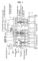
- FIG. 1 is a diagram showing an embodiment 1 of a device for producing an annular magnet, which is seen from a front thereof.
- FIG. 2 is a plan view showing an embodiment 1 of a device for producing an annular magnet.
- FIG. 3 is a diagram showing a preforming section in the embodiment 1, which is seen from a front thereof.
- FIG. 4 is a diagram showing a preforming section and a transfer robot in the embodiment 1, which is seen from a side thereof.
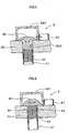
- FIG. 5 is a diagram showing the state where a charging space of the preforming section is charged with a compound.
- FIG. 6 is a diagram showing the state where a charging space of the preforming section is charged with a compound, and an excess compound is discharged.
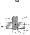
- FIG. 7 is a diagram showing the state where the compound is pressure-formed with a first upper punch and a first lower punch in the preforming section to form an annular preformed body.
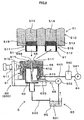
- FIG. 8 is a diagram showing a lubricant oil impregnating section in the embodiment 1, in the state where a lubricant oil is fed.
- FIG. 9 is a diagram showing the lubricant oil impregnating section in the embodiment 1, from which an excess amount of lubricant oil in the annular preformed body is sucked.
- FIG. 10 is a diagram showing a magnetic field orienting and forming section in the embodiment 1, which is seen from a front thereof.
- FIG. 11 is a diagram showing the magnetic field orienting and forming section in the embodiment 1, which is seen from a side thereof.
- FIG. 12 is a diagram showing the state where a cassette for the magnetic field orienting and forming section is advanced between a second upper punch and a second lower punch of the magnetic field orienting and forming section in the embodiment 1.
- FIG. 13 is a diagram showing the state where the second lower punch and a second core are elevated while the second upper punch is lowered in the magnetic field orienting and forming section of the embodiment 1.
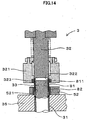
- FIG. 14 is a diagram showing the state where the change of the annular preformed body and an annular intermediate formed body is performed in the cassette for the magnetic field orienting and forming section in the embodiment 1.
- FIG. 15 is a diagram showing the state where the cassette for the magnetic field orienting and forming section is moved back from the position between the second upper punch and the second lower punch in the embodiment 1.
- FIG. 16 is a diagram showing the state where the annular preformed body is entirely inserted in a second die in the magnetic field orienting and forming section of the embodiment 1.
- FIG. 17 is a diagram showing the state where a magnetic field is applied by means of magnetic field applying means, and pressure-forming is performed by the second upper punch and the second lower punch in the magnetic field orienting and forming section of the embodiment 1, thereby forming an annular intermediate formed body.
- FIG. 18 is a diagram showing the main forming section of the embodiment 1, which is seen from a front thereof.
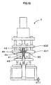
- FIG 19 is a diagram showing the main forming section of the embodiment 1, which is seen from a side thereof.
- FIG. 20 is a diagram showing the state where the change of the annular intermediate formed body and an annular magnet is performed in the cassette for the main forming section in the embodiment 1.
- FIG. 21 is a diagram showing the state where the annular intermediate formed body is entirely inserted in a third die in the main forming section of the embodiment 1.
- FIG. 22 is a diagram showing the state where pressure-forming is performed by the third upper punch and the third lower punch in the main forming section of the embodiment 1 to mold the annular magnet.
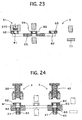
- FIG. 23 is a diagram showing the state where the transfer robot of the embodiment 1 transfers works to the cassette for the magnetic field orienting and forming section, and the cassette for the main forming section carries the works out of the device 1.
- FIG. 24 is a diagram showing the state where the cassette for the magnetic field orienting and forming section and the cassette for the main forming section of the embodiment 1 respectively carry works in the magnetic field orienting and forming section and the main forming section.
- FIG. 25 is a diagram showing the state where the change of the works is performed in the cassette for the magnetic field orienting and forming section and in the cassette for the main forming section in the magnetic field orienting and forming section and the main forming section of the embodiment 1.
- FIG. 26 is a diagram showing the state where the cassette for the magnetic field orienting and forming section and the cassette for the main forming section of the embodiment 1 respectively carry works out of the magnetic field orienting and forming section and the main forming section.
- FIG. 27 is a diagram showing the state where a loader cassette of the embodiment 1 respectively receive works from the cassette for the magnetic field orienting and forming section, the cassette for the main forming section, and a buffer section.
- FIG. 28 is a diagram showing the state where the loader cassette is fed out in the embodiment 1.
- FIG. 29 is a diagram showing the state where the loader cassette of the embodiment 1 delivers works to the cassette for the magnetic field orienting and forming section, the cassette for the main forming section, and a unloading section.
- FIG. 30 is a diagram showing the state where the loader cassette is returned in the embodiment 1.
- FIG. 31 is a schematic graph showing the generating state of a maximum output power in each section of the embodiment 1, of which abscissa is graduated by time, and ordinate is graduated by output power in each section.
- FIG. 32 is a diagram showing the state where the annular intermediate formed bodies which are piled up are pressure-formed with a third upper punch and a third lower punch in the main forming section of the embodiment 1 to mold an annular magnet.
- FIG. 33 is a diagram showing an embodiment 2 of a device for producing an arcuate magnet, which is seen from a front thereof.
- FIG. 34 is a plan view showing the embodiment 2 of a device for producing an arcuate magnet.
- FIG. 35 is a diagram showing a magnetic field orienting and forming section and work transferring section of the embodiment 2, which is seen from side thereof.
- FIG. 36 is a plan view of a pair of arcuate cavities formed in the preforming section of the embodiment 2.
- FIG. 37 is a diagram showing the state where a pair of arcuate magnets are formed by applying a magnetic field with magnetic field applying means of the magnetic field orienting and forming section of the embodiment 2, and pressure-forming with a second upper punch and a second lower punch.
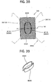
- FIG. 38 is a plan view showing the state where the magnetic field is applied with the magnetic field applying means of the magnetic field orienting and forming section of the embodiment 2.
- FIG. 39 is a perspective view of the pair of arcuate magnets, which were produced with the embodiment 2 of the device for producing the arcuate magnet.
- a device 1 for producing an annular magnet of the present embodiment is the device by which an annular magnet 83 is produced from a compound 80 containing anisotropic magnet powder with three sections including a later-describing preforming section 2, a magnetic field orienting and forming section 3 and a main forming section 4.
- the preforming section 2 has a first die 25 defining an outer peripheral wall of an annular cavity 20, a first core 23 defining an inner peripheral wall of the annular cavity 20, a first lower punch 21 defining a bottom wall of the annular cavity 20, and a first upper punch 22 facing the first lower punch 21.
- the preforming section 2 is arranged such that the above-described annular cavity 20 is charged with the compound 80 prepared by mixing an anisotropic magnet powder and a thermosetting resin, and compression-forming is performed in the annular cavity 20 with the first upper punch 22 and the first lower punch 21, thereby obtaining an annular preformed body 81.
- the magnetic field orienting and forming section 3 has a second die 35 for supporting an outer peripheral surface of the annular preformed body 81, a second core 33 for supporting an inner peripheral surface of the annular preformed body 81, a second lower punch 31 for supporting a bottom surface of the annular preformed body 81, and a second upper punch 32 facing the second lower punch 31.
- the magnetic field orienting and forming section 3 has magnetic field applying means 36 for applying a magnetic field to the annular preformed body 81, and second heating means 37 for heating the annular preformed body 81.
- the magnetic field orienting and forming section 3 heats the annular preformed body 81 with the second heating means 37, and orients the magnetic field of the anisotropic magnet powder in the annular preformed body 81 with the magnetic field applying means 36 with the thermosetting resin melted in the annular preformed body 81, and at the same time, pressure is applied to the annular preformed body 81 with the second upper punch 32 and the second lower punch 31, thereby obtaining an annular intermediate formed body 82.
- the process of orienting the magnetic field and applying pressure may be referred to as "magnetic field orienting and forming".
- the main forming section 4 has a third die 45 for supporting an outer peripheral surface of the intermediate formed body 82, a third core 43 for supporting an inner peripheral surface of the intermediate formed body 82, a third lower punch 41 for supporting a bottom surface of the annular intermediate formed body 82, a third upper punch 42 facing the third lower punch 41, and third heating means 46 for heating the annular intermediate formed body 82.
- the main forming section 4 heats the annular intermediate formed body 82, and at the same time, pressure is applied to the annular intermediate formed body 82 with the third upper punch 42 and the third lower punch 41, thereby obtaining an annular magnet 83.
- main forming the process of applying pressure in the main forming section 4 may be referred to as "main forming".
- the device 1 has a work transferring section 5 for supporting the annular preformed body 81 and transferring it from the preforming section 2 to the magnetic field orienting and forming section 3 while supporting the annular intermediate formed body 82 and transferring it from the magnetic field orienting and forming section 3 to the main forming section 4.
- the first through third upper punches 22, 32, 42, the first through third lower punches 21, 31, 41 and the first through third cores 23, 33, 43 are so arranged as to be driven with servomotors 24, 34, 44, respectively.
- the preforming section 2 has mass measuring means 26 for measuring the mass of this annular preformed body 81 after forming thereof.
- the first lower punch 21 is arranged such that the position thereof before the compression forming step is varied with the servomotor 24 based on the mass of the annular preformed body 81, which has been measured with the mass measuring means 26, to vary the volume of the annular cavity 20.
- the device 1 for producing an annular magnet in the present embodiment has a preforming section 2 provided with mass measuring means 26, magnetic field orienting and forming section 3, main forming section 4, work transferring section 5, later- described lubricating oil impregnating section 6 and work loading section 7.
- the work transferring section 5 has a later- described transfer robot 51, a cassette 52 for the magnetic field orienting and forming section, a cassette 53 for the main forming section, and a loader cassette 55.
- the preforming section 2 has a later-described transfer bar 27.
- the servomotors 24, 34, 44 for driving the first through third upper punchs 22, 32, 42 , first through third lower punches 21, 31, 41 and first through third cores 23, 33, 43 are controlled with control means (not shown).
- the operations of the mass measuring means 26, transfer bar 27, magnetic field applying means 36, transfer robot 51, cassette 52 for the magnetic field orienting and forming section, cassette 53 for the main forming section, loader cassette 55, lubricant oil impregnating section 6, work loading section 7 or the like are also controlled with the controlling means, respectively. Namely, a series of operations in the device 1 of the present embodiment are controllable with the controlling means.
- the preforming section 2, the magnetic field orienting and forming section 3, and the main forming section 4 are provided in a common base plate 10. And the preforming section 2, the magnetic field orienting and forming section 3, the main forming section 4, the work transferring section 5, the lubricating oil impregnating section 6 and the work loading section 7 are integrally secured to the base plate 10. And the base plate 10 is provided on an upper surface of a bed 11.
- the device 1 for producing an annular magnet in the present embodiment produces an annular magnet 83 from the above-described compound 80 in the following flow (see FIG 2).
- the annular preformed body 81 is formed from the compound 80 in the preforming section 2, and is transferred to the mass measuring means 26 by way of the transfer bar 27. Then, the mass of the annular preformed body 81 is measured in the mass measuring means 26, and when the measured mass is within the range of a favorable mass value, the annular preformed body 81 is transferred to the lubricant oil impregnating section 6 by means of the transfer robot 51.
- the annular preformed body 81 is impregnated with a lubricant oil 65, and then, this annular preformed body 81 is transferred to the cassette 52 for the magnetic field orienting and forming section by means of the above-described transfer robot 51.
- the annular preformed body 81 is carried in the magnetic field orienting and forming section 3 by means of the cassette 52 for the magnetic field orienting and forming section.
- the annular preformed body 81 is subjected to magnetic field orienting and forming, thereby forming the above-described annular intermediate formed body 82.
- this annular intermediate formed body 82 is carried out to the loader cassette 55 by means of the cassette 52 for the magnetic field orienting and forming section.
- the annular intermediate formed body 82 is transferred to the cassette 53 for the main forming section by means of the loader cassette 55. And the annular intermediate formed body 82 is transferred to the main forming section 4 by means of the cassette 53 for the main forming section. And in the main forming section 4, the annular intermediate formed body 82 is further formed to obtain the annular magnet 83. Then, this annular magnet 83 is carried out to the loader cassette 55 by means of the above-described cassette 53 for the main forming section.
- the annular magnet 83 is transferred to an unloading section 77 by means of the loader cassette 55, and is fed out of the device 1 to an unloading shoot 78. Then, residual magnetization in the annular magnet 83 is removed, and the annular magnet 83 is magnetized to N pole and S pole, thereby obtaining the annular magnet 83 having a magnetic force.
- the arrangement of the device 1 will be explained in detail.
- the preforming section 2 First, the preforming section 2 will be explained. As shown in FIGS. 1, 3, the preforming section 2 has an opening on the lower side thereof, and has a rubbing jig 281 that holds the compound 80 and moves on the first die 25. By this rubbing jig 281, the compound 80 can be placed on the first lower punch 21 and the first core 23. And this rubbing jig 281 is arranged such that the annular preformed body 81 after forming can be moved from the providing position of the first lower punch 21 to a prescribed transferring position.
- the preforming section 2 has a compound tank 282 for storing the compound 80. And the preforming section 2 is arranged such that the compound 80 falls from the compound tank 282 and is fed to the inside of the rubbing jig 281.
- the preforming section 2 has a transfer bar 27 for transferring the annular preformed body 81 which has been moved to the prescribed transfer position by means of the rubbing jig 281 to the mass measuring means 26.
- This transfer bar 27 is inserted in a through hole 811 of the annular preformed body 81, and transfers the annular preformed body 81 to the mass measuring means 26 while retaining the same.
- the mass measuring means 26 is so arranged as to measure the mass of the annular preformed body 81 after subjecting each of the annular preformed bodies 81 prior to the mass measurement to zero amendment. With this arrangement, the measurement accuracy of the mass measuring means 26 can be improved.
- the "zero amendment" means the resetting of this mass measuring means 26 with the value indicated by the mass measuring means 26 prior to the mass measurement as 0.
- the mass measuring means 26 is composed of a mass meter.
- the preforming section 2 has a first stationary table 201 in which the first die 25 is embedded, and a first pressure table 202 provided with the first upper punch 22. And the first pressure table 202 is so arranged as to descend upon receiving a driving force of the servomotor 24. And, the rubbing jig 281 is so arranged as to slide on the first stationary table 201, and the transfer bar 27 is so arranged as to transfer the annular preformed body 81 while sliding the same on the first stationary table 201.
- the magnetic field applying means 36 in the present embodiment is composed of a circular annular lower magnetic field coil 362 which is disposed under the second die 35, and an annular upper magnetic field coil 361 which is to be disposed above the second die 35 upon applying pressure. And in the present embodiment, a magnetic field is applied to the annular preformed body 81 in radial directions by means of a pair of upper and lower magnetic field coils 361 and 362 to orient a magnetic field in radial directions.
- the magnetic field applying means 36 may be composed of a pair of magnetic field coils that are disposed sidewardly of the second die 35 so as to hold the same. In this case, a magnetic field is applied to the annular preformed body 81 in an axial direction to enable the axial orientation of magnetic field.
- the second heating means 37 of the present embodiment is composed of a heater that is embedded in the vicinity of this second die 35 for heating the second die 35.
- the magnetic field orienting and forming section 3 has a second stationary table 301 in which the second die 35 is embedded, a second pressure table 302 provided with the second upper punch 32 and a second pressure sub-table 303 provided with the upper magnetic field coil 361.
- the second pressure table 302 is so arranged as to descend upon receiving a driving force of the servomotor 34, and the second pressure sub-table 303 is so arranged as to descend prior to the second pressure table 302.
- the second pressure table 302 is provided with a cylinder 304 (air cylinder in the present embodiment).
- the cassette 52 for the magnetic field orienting and forming section is so arranged as to carry the annular preformed body 81 in the magnetic field orienting and forming section 3 and carry the annular intermediate formed body 82 out of the magnetic field orienting and forming section 3 while sliding on the second stationary table 301.
- the second upper punch 32 has a work holder 321 which is provided slidably on an outer peripheral surface of the second upper punch 32.
- This work holder 321 has an annular cross-sectional shape, and is provided with a holder retaining part 322 which can retain the annular preformed body 81 in an inner peripheral surface thereof.
- the work holder 321 is provided with a magnet 323 in the holder holding part 322 for attracting the annular preformed body 81.
- the main forming section 4 has a third stationary table 401 in which the third die 45 is embedded, a third pressure table 402 provided with a third upper punch 42. And the third pressure table 402 is so arranged as to descend upon receiving a driving force of the servomotor 44 And, the cassette 53 for the main forming section is so arranged as to carry the annular preformed body 81 in the main forming section 4 and carry the annular intermediate formed body 82 out of the main forming section 4 while sliding on the third stationary table 401.
- the third heating means 46 of the present embodiment is composed of a heater which is embedded in the vicinity of this third die 45 for heating the third die 45.
- the third upper punch 42 has a work holder 421 that is provided slidably on its outer peripheral surface thereof.
- This work holder 421 has an annular cross-sectional shape, and is provided with a holder retaining part 422 which can retain the annular intermediate formed body 82 in its inner peripheral surface.
- the work holder 421 is provided with a magnet 423 in the holder retaining part 422 for attracting the intermediate formed body 82.
- the preforming section 2, the magnetic field orienting and forming section 3 and the main forming section 4 of the present embodiment respectively compose a motor servopress.
- the first through third upper punches 22, 32, 42, the first through third lower punches 21, 31, 41 and the first through third cores 23, 33, 43 are so arranged as to be driven with the servomotors 24, 34, 44, respectively.
- nuts (not shown) which are respectively screwed to feed screws (not shown) that rotate upon receiving the rotation force of the servomotors 24, 34, 44 are secured to the upper punches 22, 32, 42, the lower punches 21, 31, 41 and the cores 23, 33, 43.
- the rotation torques of the servomotors 24, 34, 44 are converted to thrust directed in an axial direction of the upper punches 22, 32, 42, the lower punches 21, 31, 41 and the cores 23, 33, 43 with feed screws and feed nuts.
- the lubricant oil impregnating section 6 Next, the lubricant oil impregnating section 6 will be explained. As shown in FIGS. 2, 8, 9, the device 1 for producing the annular magnet has the lubricant oil impregnating section 6 for impregnating a lubricant oil 65 in the annular preformed body 81.
- This lubricant oil impregnating section 6 has an impregnation jig 60 for disposing the annular preformed body 81, lubricant oil feeding means 63 for feeding the lubricant oil 65 to the annular preformed body 81 in this impregnation jig 60, and sucking means 64 for sucking an excess lubricant oil 65 impregnated in the annular preformed body 81 in the impregnation jig 60.
- the lubricant oil impregnating section 6 has a lubricant oil tank 631 for storing the lubricant oil 65.
- the impregnation jig 60 has a work retaining frame 61 for inserting and disposing the annular preformed body 81, and a suction box 62 which is made vacuum with the suction means 64 is disposed below the work retaining frame 61.
- a lubricant oil feed groove 611 for inserting and disposing an entire part of the annular preformed body 81 and feeding the lubricant oil thereto, is provided in the work retaining frame 61.
- a large number of suction holes 612 are formed below the lubricant oil feeding groove 611 for dropping an excess lubricant oil 65 impregnated in the annular preformed body 81 into the suction box 62.
- the work retaining frame 61 is composed of an inner periphery holding part 615 for holding an inner peripheral surface of the annular preformed body 81 along with a bottom surface thereof, and an outer periphery holding part 616 for holding an outer peripheral surface of the annular preformed body 81. And the outer periphery holding part 616 is detachable by operating a plunger 617 adapted to secure the outer periphery holding part 616.
- the lubricant oil feeding means 63 has a feeding pump 632 for feeding the lubricant oil 65 from the lubricant oil tank 631 to the impregnation jig 60, and a feeding pipe 633 for feeding the lubricant oil 65 from this feeding pump 632 to the impregnation jig 60. And a tip end 634 of the feeding pipe 633 opens in an upper surface of the impregnation jig 60 in the position inwardly of the lubricant oil feeding groove 611.
- the suction means 64 has a suction pump 641 for sucking an excess lubricant oil 65 from the annular preformed body 81, and a suction tank 642. And the suction pump 641 and the suction tank 642 are connected to the suction box 62 by way of a suction pipe 643. And the suction pump 641 is composed of a vacuum pump adapted to suck air from the suction box 62. And the excess lubricant oil 65 which has been sucked by the suction pump 641 from the annular preformed body 81 and dropped into the suction box 62 is recovered in the lubricant oil tank 631 without being sucked by the suction pump 641.
- a filter 613 is disposed in the position in which the suction pipe 643 opens in the suction tank 642 for preventing the compound 80 and the lubricant oil 65 from being sucked into the suction pump 641.
- the bottom of the suction box 62 is connected to the lubricant oil tank 631 with a return pipe 635 for returning the lubricant oil 65 which has dropped from the suction holes 612 of the impregnation jig 60 to the lubricant oil tank 631.
- the device 1 is also provided with an auxiliary impregnation jig 600 with a similar arrangement to that of the impregnation jig 60.
- the auxiliary impregnation jig 600 is so arranged as to be used instead of the impregnation jig 60 when any trouble occurs in the impregnation jig 60 during use.
- the work transferring section 5 is arranged such that works such as the preformed body 81, intermediate formed body 82, or the annular magnet 83 are transferred from the mass measuring means 26 to the lubricant oil impregnating section 6, from the lubricant oil impregnating section 6 to the magnetic field orienting and forming section 3, from the magnetic field orienting and forming section 3 to the main forming section 4, and from the main forming section 4 to the unloading section 77 .
- the work transferring section 5 of the present embodiment has the transfer robot 51, cassette 52 for the magnetic field orienting and forming section, the cassette 53 for the main forming section and the loader cassette 55.
- the transfer robot 51 holds the annular preformed body 81 prior to the impregnation with the lubricant oil, and transfers the same from the mass measuring means 26 to the lubricant oil impregnating section 6, and holds the annular preformed body 81 after the impregnation with the lubricant oil, and transfers the same from the lubricant oil impregnating section 6 to the cassette 52 for the magnetic field orienting and forming section.
- FIGS. 1 the transfer robot 51 holds the annular preformed body 81 prior to the impregnation with the lubricant oil, and transfers the same from the mass measuring means 26 to the lubricant oil impregnating section 6, and holds the annular preformed body 81 after the impregnation with the lubricant oil, and transfers the same from the lubricant oil impregnating section 6 to the cassette 52 for the magnetic field orienting and forming section.
- the cassette 52 for the magnetic field orienting and forming section receives the annular preformed body 81 from the transfer robot 51, carries the same in the magnetic field orienting and forming section 3, receives the annular intermediate formed body 82 after forming from the magnetic field orienting and forming section 3 and carries the same out of the magnetic field orienting and forming section 3.
- the loader cassette 55 receives the annular intermediate formed body 82 from the cassette 52 for the magnetic field orienting and forming section, and delivers the same to the cassette 53 for the main forming section.
- the cassette 53 for the main forming section receives the annular intermediate formed body 82 from the loader cassette 55, carries the same in the main forming section 4 and carries the annular magnet 83 from the main forming section 4 to the loader cassette 55.
- the transfer robot 51 has two work attracting parts 511, 512, each having a head part 510 which is adapted to attract the annular preformed body 81 and hold the same.
- the head part 510 has a stationary part 513 and a slide part 514 which is slidably disposed in the stationary part 513.
- a magnet 515 is provided at an end of the slide part 514.
- the transfer robot 51 is arranged such that when the slide part 514 is advanced, the annular preformed body 81 can be attracted to the magnet 515, and when the slide part 514 is moved back, the annular preformed body 81 can be separated from the magnet 515. And, the transfer robot 51 is arranged such that one work attracting part 511 can attract the annular preformed body 81 prior to impregnation with a lubricant oil, and another work attracting part 512 can attract the annular preformed body 81 after impregnation with a lubricant oil.
- the cassette 52 for the magnetic field orienting and forming section is so arranged as to hold an annular formed body 81 which will be subjected to the following magnetic field orienting and forming process, and advance to the position between the second upper punch 32 and the second lower punch 31, supply the annular formed body 81 to the second upper punch 32, receive the annular intermediate formed body 82 which has been subjected to the last magnetic field orienting and forming process, hold the annular intermediate formed body 82, and move back from the position between the second upper punch 32 and the second lower punch 31.
- the cassette 52 for the magnetic field orienting and forming section is arranged such that when the second lower punch 31 pushes the annular intermediate formed body 82 to the cassette 52 for the magnetic field orienting and forming section, cassette 52 for the magnetic field orienting and forming section receives the annular intermediate formed body 82, and when the annular preformed body 81 is pushed out by the annular intermediate formed body 82, the annular preformed body 81 is supplied to the second upper punch 32.
- the cassette 53 for the main forming section is so arranged as to hold the annular intermediate formed body 82 which will be subjected to the following main forming process, and advance to the position between the third upper punch 42 and the third lower punch 41, supply the annular intermediate formed body 82 to the third upper punch 42, receive the annular magnet 83 which has been subjected to the last main forming process, hold the annular magnet 83, and move back from the position between the third upper punch 42 and the third lower punch 41.
- the cassette 53 for the main forming section is arranged such that when the third lower punch 41 pushes the annular magnet 83 to the cassette 53 for the main forming section, cassette 53 for the main forming section receives the annular magnet 83, and when the annular intermediate formed body 82 is pushed out by the annular magnet 83, this annular intermediate formed body 82 is supplied to the third upper punch 42.
- the cassette 52 for the magnetic field orienting and forming section has a work holding hole 521 adapted for inserting the annular preformed body 81 and the annular intermediate formed body 82 therein and holding the same.
- the cassette 53 for the main forming section also has a work holding hole 531 adapted for inserting the annular magnet 83 therein and holding the same.
- the depth of the work holding hole 521 is made approximately equal to the thickness of the annular preformed body 81 or greater than the thickness of the annular preformed body 81.
- the depth of the work holding hole 531 is made approximately equal to the thickness of the annular intermediate formed body 82 or greater than the thickness of the annular intermediate formed body 82.
- the cassettes 52, 53 can transfer the preformed body 81, intermediate formed body 82 or annular magnet 83 which have been inserted in the work holding holes 521, 531, and can protect the preformed body 81, intermediate formed body 82 or annular magnet 83 to prevent cracks, damages or the like from being formed in outer peripheral surfaces thereof.
- magnets 522, 532 are respectively disposed in the work holding holes 521, 531 of the cassette 52 for the magnetic field orienting and forming section and the cassette 53 for the main forming section. And the cassettes 52, 53 are respectively arranged such that the magnets 522, 532 attract the preformed body 81 and the intermediate formed body 82, or the annular magnet 83 and hold the same.
- the second die 35 in the magnetic field orienting and forming section 3 and the third die 45 in the main forming section 4 are in the heated condition with the heating means 37 and 46. Accordingly, it is preferable that arm parts 523, 533 (see FIG. 11, FIG. 19) of the cassettes 52, 53 are composed of a material which is not considerably affected by heat. In addition, by providing cooling means such as cooling fans or radiating fins in the arm parts 523, 533, the effect of heat can be protected.
- the work holder 321 in the magnetic field orienting and forming section 3 and the work holder 421 in the main forming section 4 are composed of a material which is not considerably affected by heat.
- the work holders 321, 421 may be cooled with cooling means.
- the device 1 for producing an annular magnet in the present embodiment has a buffer section 54 for temporarily storing the annular intermediate formed body 82 in the position between the cassette 52 for the magnetic field orienting and forming section and the cassette 53 for the main forming section.
- the annular intermediate formed body 82 formed in the magnetic field orienting and forming section 3 is temporarily stored in the buffer section 54, and is carried in the main forming section 4.
- the stroke of the loader cassette 55 upon transferring the preformed body 81, the intermediate formed body 82 and the annular magnet 83 can be decreased.
- works can be transferred from the cassette 52 for the magnetic field orienting and forming section to the buffer section 54, from the buffer section 54 to the cassette 53 for the main forming section, and from the cassette 53 for the main forming part to the unloading section 77 by merely reciprocating one loader cassette 55 without increasing the dimensions of the device 1.
- the buffer section 54 has a buffer holding hole 541 for inserting and holding the annular intermediate formed body 82.
- a magnet (not shown) is disposed in this buffer holding hole 541.
- this buffer section 54 is arranged such that the magnet attracts the annular intermediate formed body 82 and holds the same.
- the loader cassette 55 has loader holding holes 551 through 553 for inserting the preformed body 81, intermediate formed body 82 or annular magnet 83 and holding the same, similarly to the cassettes 52, 53.
- the loader cassette 55 of the present embodiment has the first loader holding hole 551 for receiving the annular intermediate formed body 82 from the cassette 52 for the magnetic field orienting and forming section, and transferring the same to the buffer section 54, the second loader holding hole 552 for receiving the annular intermediate formed body 82 from the buffer section 54 and delivering the same to the cassette 53 for the main forming section, and the third loader holding hole 553 for receiving the annular magnet 83 from the cassette 53 for the main forming section and delivering the same to the unloading section 77.
- a magnet (not shown) is disposed in each of the first through third loader holding holes 551 through 553 in the loader cassette 55. And the loader cassette 55 is arranged such that each magnet attracts the preformed body 81, intermediate formed body 82 or annular magnet 83 to hold the same.
- the device 1 for producing an annular magnet in the present embodiment has a work placing section 7 which is capable of shifting works, that is the preformed body 81, intermediate formed body 82 or annular magnet 83, between the cassette 52 for the magnetic field orienting and forming section, the cassette 53 for the main forming section, buffer section 54 and loader cassette 55.
- This work shifting section 7 has the following first through sixth shifting pins 71 through 76. By moving these shifting pins 71 through 76, the works 81 through 83 can be shifted.
- the first shifting pin 71 is adapted to shift the annular intermediate formed body 82 which is held in the work holding hole 521 in the cassette 52 for the magnetic field orienting and forming section to the first loader holding hole 551 in the loader cassette 55.
- the second shifting pin 72 is adapted to shift the annular intermediate formed body 82 which is held in the buffer holding hole 541 in the buffer section 54 to the second loader holding hole 552 in the loader cassette 55.
- the third shifting pin 73 is adapted to shift the annular intermediate formed body 82 which is held in the first loader holding hole 551 in the loader cassette 55 to the buffer holding hole 541 in the buffer section 54.
- the fourth shifting pin 74 is adapted to shift the annular magnet 83 which is held in the work holding hole 531 in the cassette 53 for the main forming section to the third loader holding hole 553 in the loader cassette 55.
- the fifth shifting pin 75 is adapted to shift the annular intermediate formed body 82 which is held in the second holding hole 552 in the loader cassette 55 to the work holding hole 531 in the cassette 53 for the main forming section.
- the sixth shifting pin 76 is adapted to unload the annular magnet 83 that is held in the third holding hole 553 in the loader cassette 55 to the unloading section 77.
- the loader cassette 55 is capable of reciprocating between a receiving position 555 in which the works 81 through 83 composed of the preformed body 81, intermediate formed body 82 and magnet 83 are received, and a delivery position 556 in which the works 81 through 83 are delivered.
- the loader cassette 55 located in the receiving position 555 is so arranged as to receive the annular intermediate formed body 82 from the cassette 52 for the magnetic field orienting and forming section with the operation or the first shifting pin 71, receive the annular intermediate formed body 82 from the buffer section 54 with the operation of the second shifting pin 72, and receive the annular magnet 83 from the cassette 53 for the main forming section with the operation of the fourth shifting pin 74.
- the loader cassette 55 located in the delivery position 556 is so arranged as to deliver the annular intermediate formed body 82 from the loader cassette 55 to the buffer section 54 with the operation of the third shifting pin 73, deliver the annular intermediate formed body 82 from the loader cassette 55 to the cassette 53 for the main forming section with the operation of the fifth shifting pin 75, and unload the annular magnet 83 from the loader cassette 55 to the unloading section 77.
- preforming method Next, the method for preforming in the preforming section 2 will be explained. As shown in FIG. 1, in the preforming section 2, the rubbing jig 281 which holds the compound 80 is advanced upwardly of the first lower punch 21 and the first core 23. At this time, due to the advance of the rubbing jig 281, the annular preformed body 81 formed before, can be moved to the prescribed transfer position.
- the first lower punch 21 and the first core 23 are lowered relative to the first die 25 with the rubbing jig 281 disposed above the first lower punch 21 and the first core 23, thereby defining a charging space 200 with a volume greater than the annular cavity 20, and the charging space 200 is charged with the compound 80.
- the first lower punch 21 and the first core 23 are elevated relative to the first die 25, thereby defining the annular cavity 20 charged with the compound 80. And an excess compound 80 is discharged outwardly of this annular cavity 20. And the rubbing jig 281 holding the compound 80 is moved back to its original position (see FIG. 1).
- the first upper punch 22 is lowered to compress the compound 80 in the annular cavity 20 between the first upper punch 22 and the first lower punch 21, thereby forming the annular preformed body 81.
- this compression forming can be preformed by lowering the first core 23 along with the first upper punch 22, and applying a pressure to the compound 80 while lowering the first core 23 and the first upper punch 22 together.
- the servomotor 24 is controlled to apply an elevation thrust in the direction of the first upper punch 22 to the first core 23, and with the lowering thrust of the first upper punch 22, which is greater than this elevation thrust, the first core 23 can be lowered, following the first upper punch 22.
- the first lower punch 21 is raised to extract the annular preformed body 81 from the first die 25.
- the rubbing jig 281 can be advanced again, similarly to the above-described case.
- the annular preformed body 81 can be repeatedly formed from the compound 80, similarly.
- the annular preformed body 81 which is moved to the prescribed transfer position is transferred to the mass measuring means 26 with the transfer bar 27.
- the transfer bar 27 transfers the annular preformed body 81 to the position before reaching the mass measuring means 26, and temporarily stops transferring.
- the mass measuring means 26 performs the zero amendment to reset the value of the mass at the present time. After the zero amendment, the transfer bar 27 is started again to transfer the annular preformed body 81 from the temporarily stopped position to the mass measuring means 26.
- the mass measuring means 26 measures the mass of annular preformed body 81, and judges whether the measured mass value is within the scope of the mass values of good products or not. And when the measured mass value is within the scope of the mass values of good products, the annular preformed body 81 that is judged good is transferred to the lubricant oil impregnating section 6 by means of the transfer robot 51. On the other hand, when the measured mass value is beyond the scope of the mass values of good products, the mass measuring means 26 judges the annular preformed body 81 inferior, and removes the same from the production line by means of the transfer robot 51. And the annular preformed body 81 that is judged inferior is not transferred to the lubricant oil impregnating section 6, and can be used again as the compound 80 after crushing.
- control means monitors the measured mass values of the mass measuring means 26, and the measured mass values are feedback to the preformed section 2, and reflected therein.
- the first lower punch 21 in the preforming section 2 can vary the position before the pressure-forming (compression forming) based on the measured mass values when the mass measuring means 26 judges inferior continuously or frequently.
- the volume of the annular cavity 20 can be decreased by varying the position of the first lower punch 21 before the pressure-forming to the position shallower than the present position.
- the volume of the annular cavity 20 can be increased by varying the position of the first lower punch 21 before the pressure-forming to the position deeper than the present position.
- the above-described variation of the mass of the annular preformed body 81 is considered to be caused by the variation of the easiness of charging the annular cavity 20 with the compound 80, which is due to the difference in every rod of compound 80.
- the volume of the annular cavity 20 can be arbitrarily changed based on the mass value measured with the mass measuring means 26, and consequently, production of a large number of inferior preformed bodies 81 can be restrained.
- the transfer robot 51 transfers the annular preformed body 81 which has been judged good from the mass measuring means 26 to the lubricant oil impregnating section 6. Namely, as shown in FIG. 8, one work attracting section 511 of the transfer robot 51 attracts the preformed body 81 that has been judged good, and transfers the same to the impregnation jig 60 of the lubricant oil impregnating section 6.
- the lubricant oil 65 is fed into the impregnation jig 60 with the lubricant oil feeding means 63, and then, the annular preformed body 81 attracted on the one work attracting section 511, which has not been impregnated with the lubricant oil, is inserted in the impregnation jig 60. At this time, the lubricant oil 65 permeates an entire part of the annular preformed body 81. And, as shown in FIG.
- the lubricant oil 65 with which the annular preformed body 81 has been impregnated in the impregnation jig 60 is sucked with the sucking means 64 for a prescribed period of time, thereby sucking an excess amount of lubricant oil 65 from this annular preformed body 81.
- an entire part of the annular preformed body 81 can be impregnated with a required and sufficient amount of lubricant oil 65 approximately homogeneously.
- the interior of the second die 35 is heated to a prescribed temperature with the second heating means 37. Therefore, the annular preformed body 81 disposed in the second annular cavity 30 is heated, and thermosetting resin in this annular preformed body 81 melts to form the state in which a large number of anisotropic magnet powder can rotate and move.
- the second pressure sub-table 303 is lowered by the cylinder 304 to set the upper magnetic field coil 361 near the upper part of the second die 35.
- an electric current is supplied to the upper magnetic field coil 361 and the lower magnetic field coil 362 to generate a radial magnetic field which is directed towards an axial center of the second die 35 from the upper side and the lower side thereof, and radially flows from the axial center of the second die 35 in directions of a circumference thereof.
- the magnetic line of force in this radial magnetic field is designated by the reference character "M".
- Each anisotropic magnet powder in the annular preformed body 81 held in the second annular cavity 30 rotates and moves in the thermosetting resin due to the operation of the radial magnetic field so as to be oriented radially in the directions of the circumference of the second annular cavity 30. Consequently, the magnetization facilitating axis (direction in which magnetization is facilitated) of each anisotropic magnet powder is arranged radially in the directions of the circumference of the second annular cavity 30, whereby the orientation of the magnetic field in radial directions is prefomed.
- the second upper punch 32 is lowered with the magnetic field thus oriented to catch and compress the annular preformed body 81 in a melted state between the second upper punch 32 and the second lower punch 31, thereby forming the annular intermediate formed body 82.
- the load due to the second upper punch 32 is designated by P.
- the annular intermediate formed body 82, second die 35, second upper punch 32, second lower punch 31, second core 33 and the like are magnetized, because an electric current is supplied to the pair of upper and lower magnetic field coils 361 and 362 to perform the magnetic field orientation.
- annular intermediate formed body 82 After forming the annular intermediate formed body 82, an electric current is supplied in an opposite direction to the case where an electric current has been supplied upon orienting the magnetic field of the pair of upper and lower magnetic coils 361 and 362. And a magnetic field which is radially directed from the sides of the second die 35 towards an axial center thereof, and flows from the axial center of the second die 35 and diverges upwardly and downwardly, whereby the annular intermediate formed body 82 and the second die 35 and the second upper punch 32 , the second lower punch 31, the second core 33 and the like are demagnetized.
- the annular intermediate formed body 82 is transferred with the cassette 53 for the main forming section. And as shown in FIG. 21, this annular intermediate formed body 82 is disposed in a third annular cavity 40 defined by the third die 45, third core 43 and third lower punch 41. At this time, the interior of the third die 45 is heated to a prescribed temperature with the third heating means 46. Therefore, the annular intermediate formed body 82 disposed in the third annular cavity 40 is heated, and thermosetting resin in this annular intermediate formed body 82 melts again. It is unnecessary that this melted state is a completely melted state. A half melted state where the thermosetting resin is melted to some degree will do.
- the heating temperature of the third heating means 46 in the main forming section 4 is set higher than the heating temperature of the second heating means 37 in the magnetic field orienting and forming section 3.
- the third upper punch 42 is lowered to catch and compress the annular intermediate formed body 82 which is in the above-described melted state between the third upper punch 42 and the third lower punch 41. This compression is performed by increasing the pressure force of the third upper punch 42 greater than the pressure force of the second upper punch 32 in the magnetic field orienting and forming section 3.
- the annular intermediate formed body 82 is further compressed to form the annular magnet 83.
- the transfer robot 51 transfers the annular preformed body 81 after impregnation with a lubricant oil from the lubricant oil impregnating section 6 to the cassette 52 for the magnetic field orienting and forming section.
- the cassette 52 for the magnetic field orienting and forming section which receives the annular preformed body 81 from this transfer robot 51 holds the annular preformed body 81 in its work holding holes 521 and carries the same in the position between the second upper punch 32 and the second lower punch 31.
- the second upper punch 32 is lowered with the work holding hole 521 of the cassette 52 for the magnetic field orienting and forming section positioned between the second upper punch 32 and the second lower punch 31, and the second core 33 is inserted in a hole 811 of the preformed body 81 which is held by the cassette 52 for the magnetic field orienting and forming section.
- the second lower punch 31 is elevated with the hole 811 of the annular preformed body 81 held by the second core 33.
- unloading of the annular intermediate formed body 82 to the cassette 52 for the magnetic field orienting and forming section is performed by pushing the annular intermediate formed body 82 out in the work holding hole 521 of the cassette 52 for the magnetic field orienting and forming section with the second lower punch 31.
- the cassette 52 for the magnetic field orienting and forming section can receive the annular intermediate formed body 82 in its work holding hole 521 with the elevation of the second lower punch 31.
- the annular preformed body 81 is taken out from the cassette 52 for the magnetic filed orienting and forming section and supplied to the second upper punch 32 by pushing the annular preformed body 81 with the annular preformed body 82 out of the work holding hole 521.
- the cassette 52 for the magnetic filed orienting and forming section inserts the annular intermediate formed body 82 in the holder holding section 322 of the work holder 321 provided in the second upper punch 32 and can supply the same to the second upper punch 32.
- the annular preformed body 81 can be held with the magnet 323 provided in the work holder 321 without dropping from the second upper punch 32 (see FIG. 15).
- the change of the annular preformed body 81 and the annular intermediate formed body 82 for the cassette 52 for the magnetic field orienting and forming section can be performed with the elevating movement of the second lower punch 31.
- the unloading of the annular intermediate formed body 82 to the cassette 52 for the magnetic field orienting and forming section, removal of the annular preformed body 81 from the cassette 52 for the magnetic field orienting and forming section and supply thereof to the second upper punch 32 can be performed with only the elevating movement of the second lower punch 31 approximately simultaneously.
- the annular intermediate formed body 82 is carried from the position between the second upper punch 32 and the second lower punch 31 by means of the cassette 52 for the magnetic field orienting and forming section.
- the magnetic field orienting and forming is performed in the magnetic field orienting and forming section 3
- the cassette 52 for the magnetic field orienting and forming section carries the annular intermediate formed body 82 out of the magnetic field orienting and forming section 3 at the time when the magnetic field orienting and forming are performed in the magnetic field orienting and forming section 3.
- the carrying method by the cassette 52 for the magnetic field orienting and forming section has been explained.
- the carrying method by the cassette 53 for the main forming section is similar thereto.
- the flow of transferring works with the cassette 52 for the magnetic field orienting and forming section, cassette 53 for the main forming section, loader cassette 55 and first through sixth shifting pins 71 through 76 will be explained.
- the annular preformed body 81 is transferred to the cassette 52 for the magnetic field orienting and forming section from the transfer robot 51.
- the cassette 53 for the main forming section carries the annular magnet 83 out of the main forming section 4.
- the buffer section 54 holds the annular intermediate formed body 82.
- the cassette 52 for the magnetic field orienting and forming section carries the annular preformed body 81 in the magnetic field orienting and forming section 3 and the cassette 53 for the main forming section carries the annular intermediate formed body 82 in the main forming section 4.
- change of the annular preformed body 81 and the annular intermediate formed body 82 is performed for the cassette 52 for the magnetic field orienting and forming section.
- the change of the annular intermediate formed body 82 and the annular magnet 83 is performed for the cassette 53 for the main forming section.
- the cassette 52 for the magnetic field orienting and forming section carries the annular intermediate formed body 82 out of the magnetic field orienting and forming section 3, and the cassette 53 for the main forming section carries the annular magnet 83 out of the main forming section 4.
- the first shifting pin 71 shifts the annular intermediate formed body 82 from the cassette 52 for the magnetic field orienting and forming section to the first loader holding hole 551 of the loader cassette 55 located in the receiving position 555
- the second shifting pin 72 shifts the annular intermediate formed body 82 from the buffer section 54 to the second loader holding hole 552 of the loader cassette 55
- the fourth shifting pin 74 shifts the annular magnet 83 from the cassette 53 for the main forming section to the third loader holding hole 553 of the loader cassette 55.
- the loader cassette 55 is sent to the delivering position 556 from the receiving position 555.
- the third shifting pin 73 shifts the annular intermediate formed body 82 from the first loader holding hold 551 of the loader cassette 55 to the buffer section 54
- the fifth shifting pin 75 shifts the annular intermediate formed body 82 from the second loader holding hole 552 of the loader cassette 55 to the cassette 53 for the main forming section
- the sixth shifting pin 76 unloads the annular magnet 83 from the third loader holding hole 553 of the loader cassette 55 to the unloading section 77.
- the loader cassette 55 is returned from the delivering position 556 to the receiving position 555.
- the above-described operations are repeated, similarly, thereby performing the continuous work transfer operation.
- the space 200 with a volume greater than that of the annular cavity 20 is temporarily charged with the compound 80, and an excess amount of compound 80 is discharged to carry out the discharging of the annular cavity 20 with the compound 80.
- the charging amount of the compound 80 can be stabilized.
- the compound 80 is compressed by lowering the first upper punch 22 and the first core 23 while linking with each other. Therefore, the compound 80 can be compressed approximately homogeneously, whereby the annular preformed body 81 of which the density does not locally scatter greatly can be formed.
- the mass of all of the annular preformed bodies 81 can be measured with the mass measuring means 26. And, only when the mass of the annular preformed body 81 is within the range of mass values of good products, the annular preformed body 81 can be transferred to the following magnetic field orienting and forming section 3 with the work transferring section 5. On the other hand, when the mass of the annular preformed body 81 is out of the range of mass values of good products, the annular preformed body 81 can be stopped from being transferred to the following magnetic field orienting and forming section 3.
- the annular preformed body 81 which has been judged inferior can be reused as the compound 80 after being broken outside of the device 1. Therefore, the compound 80 is scarcely wasted, thereby improving the yield in the device 1.
- the first lower punch 21 in the preforming section 2 can vary its position prior to the compression forming based on the mass of the annular preformed body 81, which has been measured with the mass measuring means 26. Therefore, when the mass measuring means 26 continuously or frequently judges inferior, the volume of the annular cavity 20 can be arbitrarily varied by varying the position of the first lower punch 21 prior to the pressure-forming. Consequently, the mass of the annular preformed body 81 to be supplyed to the magnetic field orienting and forming section 3 can be further stabilized.
- the annular intermediate formed body 82 can be formed from the annular preformed body 81 of which the mass is stabilized, and which contains the anisotropic magnet powder with a stabilized content. Accordingly, when the annular preformed body 81 is subjected to the magnetic field orientation and forming, the annular intermediate formed body 82 can be formed with the content of anisotropic magnet powder stabilized. Consequently, when the annular magnet 83 is formed from the annular intermediate formed body 82 in the main forming section 4, and magnetized to N pole and S pole, the annular magnet 83 with excellent magnet characteristics can be produced stably.
- the annular magnet 83 by forming the annular magnet 83 at a temperature higher than that in the preforming section 2, and under a pressure greater than that in the preforming section 2, in the main forming section 4, the annular magnet 83 with an excellent dimensional accuracy can be formed. Therefore, with the device 1 for producing the annular magnet, the annular magnets 83 of which the masses are stabilized, and which are excellent in dimensional accuracy and magnet performance can be produced repeatedly.
- the position, pressure applying rate, pressure force or the like of all the upper punches 22, 32, 42, lower punches 21, 31, 41 and cores 23, 33, 43 in the preforming section 2, magnetic field orienting and forming section 3 and main forming section 4 are controllable by means of the servomotors 24, 34 and 44. Accordingly, by controlling the servomotors 24, 34, 44, the position of each of the upper punches 22, 32, 42, lower punches 21, 31, 41 and cores 23, 33, 43 can be finely adjusted, and the pressure applying rate, pressure force or the like thereof can be also adjusted.
- the forming conditions in the preforming section 2, magnetic field orienting and forming section 3 and the main forming section 4 can be made most suitable, whereby the annular magnets 83 of which the scattering in mass can be further reduced, and of which the dimensional accuracy and magnet performance are further improved can be produced repeatedly.
- FIG. 31 diagrammatically shows the state in which the pressure-forming in each of the sections 2, 3, 4 is performed with different timings to generate a maximum electric power with different timings in the preforming section 2, magnetic field orienting and forming section 3 and the main forming section 4.
- Fig. 31 is a graph of which ordinate is graduated by time t while abscissa is graduated by output power E in each of the preforming section 2, magnetic field orienting and forming section 3 and the main forming section 4.
- the timing when the first upper punch 22, the first lower punch 21 and the first core 23 are moved by means of the servomotor 24 to perform pressure-forming in the preforming section 2 the timing when an electric current is supplied to a pair of upper and lower magnetic coils 361, 362 and the second upper punch 32, second lower punch 31 and second core 33 are moved by means of the servomotor 34 to perform pressure-forming in the magnetic field orienting and forming section 3
- the timing when the third upper punch 42, third lower punch 41 and the third core 43 are moved by the servomotor 44 to perform pressure-forming in the main forming section 4 are made different intentionally.
- the cassette 52 for the magnetic field orienting and forming section which can approximately simultaneously supply the annular preformed body 81 to the second upper punch 32 and receive the annular intermediate formed body 82 from the second lower punch 31, the period of time required to carry the annular preformed body 81 into the magnetic field orienting and forming section 3 and carry the annular intermediate formed body 82 out of the magnetic field orienting and forming section 3 can be reduced.
- the cassette 53 for the main forming section which can approximately simultaneously supply the annular intermediate formed body 82 to the third upper punch 42 and receive the annular magnet 83 from the third lower punch 41, the period of time required to carry the annular intermediate formed body 82 into the main forming section 4 and carry the annular magnet 83 out of the main forming section 4 can be also reduced.
- the transfer of works with the cassette 52 for the magnetic field orienting and forming section, the cassette 53 for the main forming section, and the loader cassette 55 can be performed while the magnetic field orienting and forming section 3 or the main forming section 4 performs pressure-forming.
- the preforming section 2, the magnetic field orienting and forming section 3 and the main forming section 4 can perform their operations simultaneously and continuously. For these reasons, the period of time required for transferring works in the device 1 can be reduced, and the number of the annular magnets 83, which can be produced per unit production time, can be increased. And consequently, the device 1 for producing annular magnets with excellent productivity can be effected.
- the transfer of works with the cassette 52 for the magnetic field orienting and forming section, the cassette 53 for the main forming section, and the loader cassette 55 can be performed with the preformed body 81, intermediate formed body 82 or annular magnet 83 inserted in the work holding holes 521, 531 or loader holding holes 551 through 553. Therefore, the transfer of works can be performed without braking or damaging the preformed body 81, intermediate formed body 82 or annular magnet 83.
- each of the preforming section 2, the magnetic field orienting and forming section 3 and the main forming section 4 is composed of an electric servo press using each of the servomotors 24, 34, 44. Accordingly, each of the sections 2, 3, 4 can be made compact, as compared with conventional electric crank type press or hydraulic press. Therefore, the device 1 can be arranged compact although three sections 2, 3, 4 are included, and the annular magnet 83 can be produced from the compound 80 continuously.
- the device 1 can be also arranged such that a plurality of annular intermediate formed bodies 82 which have been formed in the magnetic field orienting and forming section 3 are stacked, and in the main forming section 4, the intermediate formed bodies 82 which are stacked into two or three layers, for example, are pressure-formed with the third upper punch 42 and the third lower punch 43.
- the annular intermediate formed bodies 82 are jointed to each other in an axial direction thereof by pressure-forming the annular intermediate formed bodies 82 which are stacked, in the main forming section 4, whereby annular magnets 83 with required thicknesses (axial heights) can be obtained.
- a device 1A for producing an arcuate magnet of the present embodiment is the device by which a pair of arcuate magnets 83A (See FIG. 39) are produced from a compound 80 containing anisotropic magnet powder with two sections including a later-described preforming section 2A and a magnetic field orienting and forming section 3A.
- the preforming section 2A of the present embodiment has a first die 25A defining an outer peripheral part of a pair of arcuate cavities 20A which face each other, a first core 23A defining an inner peripheral part of the cavities 20A, a first lower punch 21A defining a bottom wall of each cavity 20A, and a first upper punch 22A facing the first lower punch 21A.
- the preforming section 2A is arranged such that the compound 80 prepared by mixing an anisotropic magnet powder and a thermosetting resin is charged in the above-described arcuate cavities 20A, and compression-forming is performed in the arcuate cavities 20A with the first upper punch 22A and the first lower punch 21A, thereby obtaining a pair of arcuate preformed bodies 81A.
- the magnetic field orienting and forming section 3A of the present embodiment has a second die 35A for supporting an outer peripheral surface of each arcuate preformed body 81A, a second core 33A for supporting an inner peripheral surface of each arcuate preformed body 81A, a second lower punch 31A for supporting a bottom surface of each arcuate preformed body 81A, a second upper punch 32A facing the second lower punch 31A, magnetic field applying means 36A adapted to apply a magnetic field to the arcuate preformed body 81A, and heating means 37A adapted to heat the arcuate preformed body 81A.
- the magnetic field orienting and forming section 3A heats the arcuate preformed body 81A with the heating means 37A, orienting the magnetic field of the anisotropic magnet powder in the arcuate preformed body 81A with the magnetic field applying means 36A with the thermosetting resin melted in the arcuate preformed body 81A, and at the same time, pressure is applied to the arcuate preformed body 81A with the second upper punch 32A and the second lower punch 31A, thereby obtaining a pair of arcuate magnets 83A.
- the preforming section 2A has mass measuring means 26A for measuring the mass of the pair of arcuate preformed bodies 81A after forming thereof.
- the first lower punch 21A is arranged such that the position thereof before the compression-forming step is varied with the servomotor 24A for driving the first lower punch 21A based on the mass of the arcuate preformed body 81A, which has been measured with the mass measuring means 26A, to vary the volume of the pair of arcuate cavities 20A.
- the device 1A for producing a pair of arcuate magnets in the present embodiment produces a pair of arcuate magnets 83A from the above-described compound 80 in the following flow (see the drawings). Namely, first, as shown in FIGS. 33, 34, the arcuate preformed body 81A is formed from the compound 80 in the preforming section 2A, and is transferred to the mass measuring means 26A by means of a transfer unit 27A.
- the mass of the pair of arcuate preformed bodies 81A is measured with the mass measuring means 26A, and when the measured mass is within the range of favorable mass values, the pair of arcuate preformed bodies 81A are transferred to the lubricant oil impregnating section 6A by means of a transfer robot 51 A.
- each arcuate preformed body 81A which has been impregnated with the lubricant oil 65 is transferred to the magnetic field orienting and forming section 3A by means of the loader 52A for the magnetic field orienting and forming section.
- magnetic field orienting and forming are performed on each arcuate preformed body 81A to form a pair of arcuate magnets 83A. Then, the pair of arcuate magnets 83A are carried out to a first shuttle 55A by means of the loader 52A for the magnetic field orienting and forming section.
- each arcuate magnet 83A is transferred to a demagnetizing section 57A by means of the first shuttle 55A and a second shuttle 56A, and in this demagnetizing section 57A, each arcuate magnet 83A is demagnetized (removal of residual magnetization) and powder is removed. Then, each arcuate magnet 83A is magnetized to N pole and S pole in an outside of the device 1A, thereby obtaining the arcuate magnet 83A having a magnetic force.
- the arrangement of the device 1A for producing arcuate magnets in the present embodiment will be explained in detail.
- the pair of arcuate magnets 83A to be produced in the present embodiment respectively have a roof tile-shaped configuration.
- the pair of arcuate cavities 20A in the preforming section 2A define two spaces, each having a roof tile-shaped configuration, so as to face each other with respect to an axial center of the first core 23A.
- the pair of arcuate cavities 20A are formed such that inner peripheries of the spaces, each having the roof tile-shaped configuration, face each other.
- the first core 23A is so arranged as to define the inner peripheral parts of the arcuate cavities 20A, and define a pair of circumferential ends of the arcuate cavities 20A.
- the first lower punch 21 A and the first upper punch 22A are arranged to have configurations like a pair of roof tiles, each protruding in facing directions, and define bottom parts (axial end parts) of the arcuate cavities 20A.
- the first die 25A is arranged to define an outer peripheral part of each arcuate cavity 20A in a part of the inner peripheral surface thereof, and to slide on the first core 23A in a remaining part of the inner peripheral surface thereof.
- the transfer unit 27A of the present embodiment attracts the pair of arcuate preformed bodies 81A with a magnetic force, and transfers the same from the preforming section 2A to the mass measuring means 26A.
- the magnetic field applying means 36A in the magnetic field orienting and forming section 3A is composed of a pair of magnetic field coils 361A, which are disposed so as to catch the second die 35A on both sides thereof. And, by applying a magnetic field from one magnetic field coil 361A to the other magnetic field coil 361A, a magnetic field is applied in a direction of the thickness of each arcuate preformed body 81A, thereby performing orientation of the axial magnetic field. And consequently, the magnetization facilitating axis (the direction in which magnetization is facilitated) of each anisotropic magnet powder in each arcuate preformed body 81A is arranged in a direction of the thickness thereof (circumferential direction).
- the work transferring section 5A of the present embodiment is arranged such that works composed of a pair of arcuate preformed body 81A or a pair of arcuate magnets 83A are transferred from the mass measuring means 26A to the lubricant oil impregnating section 6A, from the lubricant oil impregnating section 6A to the magnetic field orienting and forming section 3A, and from the magnetic field orienting and forming section 3A to the demagnetizing section 57A.
- the work transferring section 5A of the present embodiment is composed of a transfer robot 51A, a loader 52A for the magnetic field orienting and forming section, a first shuttle 55A and a second shuttle 56A.
- the loader 52A for the magnetic field orienting and forming section receives a pair of arcuate preformed bodies 81A from the transfer robot 51A, carries the same in the magnetic field orienting and forming section 3A, receives a pair of arcuate magnets 83A which have been formed from the magnetic field orienting and forming section 3A, and carries the same out to the demagnetizing section 57A.
- the loader 52A for the magnetic field orienting and forming section has two holding parts 521A, each being capable of holding the pair of arcuate preformed bodies 81A, and is so arranged as to carry the pair of arcuate preformed bodies 81A held in one of the holding parts 521A in the magnetic field orienting and forming section 3A, hold the pair of arcuate magnets 83A after formed in the other holding part 521A and carry the same out of the magnetic field orienting and forming section 3A.
- the first shuttle 55A is so arranged as to receive a pair of arcuate magnets 83A from the loader 52A for the magnetic field orienting and forming section, and transfer the same to the second shuttle 56A.
- the second shuttle 56A is so arranged as to transfer the pair of arcuate magnets 83A received from the first shuttle 55A to the demagnetizing section 57A, and unloads the arcuate magnets 83 which have been demagnetized and from which powder is removed in the demagnetizing section 57A from the device 1A.
- the work transferring section 5A of the present embodiment has preheating means 58A which preheats the pair of arcuate preformed bodies 81A before transferring the same to the magnetic field orienting and forming section 3A.
- This preheating means 58A is so arranged as to preheat each arcuate preformed body 81A held in one of the holding parts 521A of the loader 52A for the magnetic field orienting and forming section.
- each arcuate preformed body 81A can be previously heated before transferring the same in the magnetic field orienting and forming section 3A, and accordingly, orienting of the magnetic field and pressure-forming can be speedily started in the magnetic field orienting and forming section 3A.
- the preheating means 58A of the present embodiment performs the heating operation using fluid (oil pressure in the present embodiment).
- the heating means 37A in the magnetic field orienting and forming section 3A also performs the heating operation using fluid (oil pressure in the present embodiment).
- the magnetic field orienting and forming section 3A also has the function of the main forming section 4 of the embodiment 1.
- both the orientation of the magnetic field and the main forming are performed, thereby forming the arcuate magnets 83A to have prescribed dimensions. Accordingly, the main forming section 4 can be omitted, and the cost of the device 1A for producing the arcuate magnets can be decreased and the construction thereof can be made compact.
- a pair of arcuate magnets 83A can be produced instead of the annular magnet 83.
- the arrangement and operation of each of the preforming section 2A, magnetic field orienting and forming section 3A, or the like of the present embodiment are similar to those of the embodiment 1.
- Each section in the device 1A of the present embodiment is designated by adding A to the reference character used in the embodiment 1.
- the annular magnet 83 was produced, whereas with the device of the embodiment 2, the pair of arcuate magnets 83A were produced.
- the pair of arcuate magnets 83A can be produced, whereas with the device of the embodiment 2, the annular magnet 83 can be produced.
- the arcuate magnet 83A may be composed of four pieces. The remaining constructions of these modified embodiments are similar to those of embodiment 1, and accordingly, operational advantages similar to those of the embodiment 1 can be effected.
- the device for producing the annular magnet for example, includes a preforming section for obtaining an annular preformed body from a compound of a mixture of an anisotropic magnet powder and a thermosetting resin, a magnetic field orienting and forming section for obtaining an annular intermediate formed body by subjecting the annular preformed body to orienting and pressure-forming, a main forming section for obtaining an annular magnet by further forming the annular intermediate formed body, and a work transferring section for transferring works.
- the preforming section is provided with mass measuring means for measuring the mass of the annular preformed body, and a first lower punch of the preforming section is so arranged as to vary the volume of an annular cavity by varying the position thereof, which is before the pressure-forming process with a servomotor based on the mass of preformed body, which has been measured with the mass measuring means.
Landscapes
- Engineering & Computer Science (AREA)
- Power Engineering (AREA)
- Manufacturing & Machinery (AREA)
- Manufacturing Cores, Coils, And Magnets (AREA)
Priority Applications (2)
| Application Number | Priority Date | Filing Date | Title |
|---|---|---|---|
| EP20040027419 EP1659596B1 (fr) | 2004-11-18 | 2004-11-18 | Dispositif pour produire un aimant annulaire ou courbé |
| DE200460015304 DE602004015304D1 (de) | 2004-11-18 | 2004-11-18 | Vorrichtung zur Herstellung eines Ringmagneten oder eines gekrümmten Magneten |
Applications Claiming Priority (1)
| Application Number | Priority Date | Filing Date | Title |
|---|---|---|---|
| EP20040027419 EP1659596B1 (fr) | 2004-11-18 | 2004-11-18 | Dispositif pour produire un aimant annulaire ou courbé |
Publications (2)
| Publication Number | Publication Date |
|---|---|
| EP1659596A1 true EP1659596A1 (fr) | 2006-05-24 |
| EP1659596B1 EP1659596B1 (fr) | 2008-07-23 |
Family
ID=34927445
Family Applications (1)
| Application Number | Title | Priority Date | Filing Date |
|---|---|---|---|
| EP20040027419 Expired - Fee Related EP1659596B1 (fr) | 2004-11-18 | 2004-11-18 | Dispositif pour produire un aimant annulaire ou courbé |
Country Status (2)
| Country | Link |
|---|---|
| EP (1) | EP1659596B1 (fr) |
| DE (1) | DE602004015304D1 (fr) |
Citations (2)
| Publication number | Priority date | Publication date | Assignee | Title |
|---|---|---|---|---|
| EP0265016A2 (fr) * | 1986-10-20 | 1988-04-27 | Philips Electronics Uk Limited | Procédé pour la production d'un aimant permanent |
| US5672363A (en) * | 1990-11-30 | 1997-09-30 | Intermetallics Co., Ltd. | Production apparatus for making green compact |
-
2004
- 2004-11-18 DE DE200460015304 patent/DE602004015304D1/de not_active Expired - Lifetime
- 2004-11-18 EP EP20040027419 patent/EP1659596B1/fr not_active Expired - Fee Related
Patent Citations (2)
| Publication number | Priority date | Publication date | Assignee | Title |
|---|---|---|---|---|
| EP0265016A2 (fr) * | 1986-10-20 | 1988-04-27 | Philips Electronics Uk Limited | Procédé pour la production d'un aimant permanent |
| US5672363A (en) * | 1990-11-30 | 1997-09-30 | Intermetallics Co., Ltd. | Production apparatus for making green compact |
Also Published As
| Publication number | Publication date |
|---|---|
| EP1659596B1 (fr) | 2008-07-23 |
| DE602004015304D1 (de) | 2008-09-04 |
Similar Documents
| Publication | Publication Date | Title |
|---|---|---|
| CN108702069B (zh) | 磁体嵌入式芯的制造装置和制造方法 | |
| JP6533635B1 (ja) | ロータコア保持治具、磁石埋込み型コアの製造装置及び製造方法 | |
| CN1171249C (zh) | 稀土合金粉末的压型体制造方法、成形装置及稀土磁铁 | |
| JP6280137B2 (ja) | 希土類焼結磁石の製造方法及び当該製法にて使用される製造装置 | |
| CA2056690C (fr) | Methode permettant de produire un aimant permanent et un comprime fritte ainsi que production d'un comprime cru | |
| CN104641434B (zh) | 永久磁铁的制造方法、永久磁铁的制造装置、永久磁铁以及旋转电机 | |
| US8328954B2 (en) | Method of manufacturing permanent magnet | |
| US8128757B2 (en) | Method of manufacturing oriented body, molded body and sintered body as well as method of manufacturing permanent magnet | |
| JP4426373B2 (ja) | 環状又は弧状磁石の製造装置 | |
| EP0513891A1 (fr) | Aimant pressé à chaud dans des presses ouvertes à l'air | |
| US7367791B2 (en) | Device for producing annular or arcuate magnet | |
| JPH04363010A (ja) | 永久磁石の製造方法、製造装置及び磁界中配向成形用ゴムモールド | |
| JPH0696973A (ja) | 永久磁石の製造方法 | |
| JP3060104B2 (ja) | ラジアル配向した磁気異方性樹脂結合型磁石及びその製造方法 | |
| EP1659596B1 (fr) | Dispositif pour produire un aimant annulaire ou courbé | |
| WO2010134578A1 (fr) | Appareil de fabrication d'un aimant fritté | |
| JPH10259403A (ja) | 圧縮成形装置および圧縮成形方法 | |
| JPH0543904A (ja) | 永久磁石圧粉体の製造方法 | |
| CN112846175A (zh) | 一种利用电-磁能实现粉末高速压实和烧结的装置及方法 | |
| JPH10264119A (ja) | 圧縮成形装置および圧縮成形方法 | |
| JP4166169B2 (ja) | リング型焼結磁石及びその製造方法 | |
| JP2005226108A (ja) | リング型焼結磁石の製造方法及び製造装置 | |
| JP2018078190A (ja) | 希土類磁石の製造方法 | |
| WO2024189868A1 (fr) | Dispositif de production d'aimant lié par compression et son procédé de production | |
| CN222867359U (zh) | 一种钕铁硼粘结磁环自动充磁设备 |
Legal Events
| Date | Code | Title | Description |
|---|---|---|---|
| PUAI | Public reference made under article 153(3) epc to a published international application that has entered the european phase |
Free format text: ORIGINAL CODE: 0009012 |
|
| 17P | Request for examination filed |
Effective date: 20041118 |
|
| AK | Designated contracting states |
Kind code of ref document: A1 Designated state(s): AT BE BG CH CY CZ DE DK EE ES FI FR GB GR HU IE IS IT LI LU MC NL PL PT RO SE SI SK TR |
|
| AX | Request for extension of the european patent |
Extension state: AL HR LT LV MK YU |
|
| 17Q | First examination report despatched |
Effective date: 20061215 |
|
| AKX | Designation fees paid |
Designated state(s): DE FR GB |
|
| GRAP | Despatch of communication of intention to grant a patent |
Free format text: ORIGINAL CODE: EPIDOSNIGR1 |
|
| GRAS | Grant fee paid |
Free format text: ORIGINAL CODE: EPIDOSNIGR3 |
|
| GRAA | (expected) grant |
Free format text: ORIGINAL CODE: 0009210 |
|
| AK | Designated contracting states |
Kind code of ref document: B1 Designated state(s): DE FR GB |
|
| REG | Reference to a national code |
Ref country code: GB Ref legal event code: FG4D |
|
| REF | Corresponds to: |
Ref document number: 602004015304 Country of ref document: DE Date of ref document: 20080904 Kind code of ref document: P |
|
| PLBE | No opposition filed within time limit |
Free format text: ORIGINAL CODE: 0009261 |
|
| STAA | Information on the status of an ep patent application or granted ep patent |
Free format text: STATUS: NO OPPOSITION FILED WITHIN TIME LIMIT |
|
| 26N | No opposition filed |
Effective date: 20090424 |
|
| PGFP | Annual fee paid to national office [announced via postgrant information from national office to epo] |
Ref country code: DE Payment date: 20101129 Year of fee payment: 7 |
|
| PGFP | Annual fee paid to national office [announced via postgrant information from national office to epo] |
Ref country code: GB Payment date: 20101123 Year of fee payment: 7 |
|
| PGFP | Annual fee paid to national office [announced via postgrant information from national office to epo] |
Ref country code: FR Payment date: 20111125 Year of fee payment: 8 |
|
| GBPC | Gb: european patent ceased through non-payment of renewal fee |
Effective date: 20121118 |
|
| REG | Reference to a national code |
Ref country code: FR Ref legal event code: ST Effective date: 20130731 |
|
| REG | Reference to a national code |
Ref country code: DE Ref legal event code: R119 Ref document number: 602004015304 Country of ref document: DE Effective date: 20130601 |
|
| PG25 | Lapsed in a contracting state [announced via postgrant information from national office to epo] |
Ref country code: DE Free format text: LAPSE BECAUSE OF NON-PAYMENT OF DUE FEES Effective date: 20130601 |
|
| PG25 | Lapsed in a contracting state [announced via postgrant information from national office to epo] |
Ref country code: FR Free format text: LAPSE BECAUSE OF NON-PAYMENT OF DUE FEES Effective date: 20121130 Ref country code: GB Free format text: LAPSE BECAUSE OF NON-PAYMENT OF DUE FEES Effective date: 20121118 |