EP1660362B1 - Procede et dispositif pour saisir la distance momentanee separant un vehicule d'un obstacle - Google Patents
Procede et dispositif pour saisir la distance momentanee separant un vehicule d'un obstacle Download PDFInfo
- Publication number
- EP1660362B1 EP1660362B1 EP04764364A EP04764364A EP1660362B1 EP 1660362 B1 EP1660362 B1 EP 1660362B1 EP 04764364 A EP04764364 A EP 04764364A EP 04764364 A EP04764364 A EP 04764364A EP 1660362 B1 EP1660362 B1 EP 1660362B1
- Authority
- EP
- European Patent Office
- Prior art keywords
- control unit
- vehicle
- distance sensors
- motor vehicle
- driving path
- Prior art date
- Legal status (The legal status is an assumption and is not a legal conclusion. Google has not performed a legal analysis and makes no representation as to the accuracy of the status listed.)
- Expired - Lifetime
Links
- 238000000034 method Methods 0.000 title abstract description 10
- 238000001514 detection method Methods 0.000 description 23
- 230000008859 change Effects 0.000 description 4
- 230000003068 static effect Effects 0.000 description 4
- 230000008901 benefit Effects 0.000 description 3
- 238000011156 evaluation Methods 0.000 description 3
- 238000005259 measurement Methods 0.000 description 3
- 230000005540 biological transmission Effects 0.000 description 2
- 238000012508 change request Methods 0.000 description 2
- 230000001419 dependent effect Effects 0.000 description 2
- 230000004069 differentiation Effects 0.000 description 2
- 230000001133 acceleration Effects 0.000 description 1
- 230000006978 adaptation Effects 0.000 description 1
- 230000006735 deficit Effects 0.000 description 1
- 238000002592 echocardiography Methods 0.000 description 1
- 230000006872 improvement Effects 0.000 description 1
- 238000002955 isolation Methods 0.000 description 1
- 238000004519 manufacturing process Methods 0.000 description 1
- 238000000691 measurement method Methods 0.000 description 1
- 230000007246 mechanism Effects 0.000 description 1
- 238000012544 monitoring process Methods 0.000 description 1
- 230000003287 optical effect Effects 0.000 description 1
- 230000005855 radiation Effects 0.000 description 1
- 230000035484 reaction time Effects 0.000 description 1
- 230000002441 reversible effect Effects 0.000 description 1
- 230000035945 sensitivity Effects 0.000 description 1
- 230000001629 suppression Effects 0.000 description 1
- 230000002123 temporal effect Effects 0.000 description 1
- 230000001960 triggered effect Effects 0.000 description 1
- 238000002604 ultrasonography Methods 0.000 description 1
Images
Classifications
-
- B—PERFORMING OPERATIONS; TRANSPORTING
- B60—VEHICLES IN GENERAL
- B60T—VEHICLE BRAKE CONTROL SYSTEMS OR PARTS THEREOF; BRAKE CONTROL SYSTEMS OR PARTS THEREOF, IN GENERAL; ARRANGEMENT OF BRAKING ELEMENTS ON VEHICLES IN GENERAL; PORTABLE DEVICES FOR PREVENTING UNWANTED MOVEMENT OF VEHICLES; VEHICLE MODIFICATIONS TO FACILITATE COOLING OF BRAKES
- B60T7/00—Brake-action initiating means
- B60T7/12—Brake-action initiating means for automatic initiation; for initiation not subject to will of driver or passenger
- B60T7/22—Brake-action initiating means for automatic initiation; for initiation not subject to will of driver or passenger initiated by contact of vehicle, e.g. bumper, with an external object, e.g. another vehicle, or by means of contactless obstacle detectors mounted on the vehicle
-
- B—PERFORMING OPERATIONS; TRANSPORTING
- B60—VEHICLES IN GENERAL
- B60K—ARRANGEMENT OR MOUNTING OF PROPULSION UNITS OR OF TRANSMISSIONS IN VEHICLES; ARRANGEMENT OR MOUNTING OF PLURAL DIVERSE PRIME-MOVERS IN VEHICLES; AUXILIARY DRIVES FOR VEHICLES; INSTRUMENTATION OR DASHBOARDS FOR VEHICLES; ARRANGEMENTS IN CONNECTION WITH COOLING, AIR INTAKE, GAS EXHAUST OR FUEL SUPPLY OF PROPULSION UNITS IN VEHICLES
- B60K31/00—Vehicle fittings, acting on a single sub-unit only, for automatically controlling vehicle speed, i.e. preventing speed from exceeding an arbitrarily established velocity or maintaining speed at a particular velocity, as selected by the vehicle operator
- B60K31/0008—Vehicle fittings, acting on a single sub-unit only, for automatically controlling vehicle speed, i.e. preventing speed from exceeding an arbitrarily established velocity or maintaining speed at a particular velocity, as selected by the vehicle operator including means for detecting potential obstacles in vehicle path
-
- G—PHYSICS
- G01—MEASURING; TESTING
- G01S—RADIO DIRECTION-FINDING; RADIO NAVIGATION; DETERMINING DISTANCE OR VELOCITY BY USE OF RADIO WAVES; LOCATING OR PRESENCE-DETECTING BY USE OF THE REFLECTION OR RERADIATION OF RADIO WAVES; ANALOGOUS ARRANGEMENTS USING OTHER WAVES
- G01S13/00—Systems using the reflection or reradiation of radio waves, e.g. radar systems; Analogous systems using reflection or reradiation of waves whose nature or wavelength is irrelevant or unspecified
- G01S13/88—Radar or analogous systems specially adapted for specific applications
- G01S13/93—Radar or analogous systems specially adapted for specific applications for anti-collision purposes
- G01S13/931—Radar or analogous systems specially adapted for specific applications for anti-collision purposes of land vehicles
-
- B—PERFORMING OPERATIONS; TRANSPORTING
- B60—VEHICLES IN GENERAL
- B60T—VEHICLE BRAKE CONTROL SYSTEMS OR PARTS THEREOF; BRAKE CONTROL SYSTEMS OR PARTS THEREOF, IN GENERAL; ARRANGEMENT OF BRAKING ELEMENTS ON VEHICLES IN GENERAL; PORTABLE DEVICES FOR PREVENTING UNWANTED MOVEMENT OF VEHICLES; VEHICLE MODIFICATIONS TO FACILITATE COOLING OF BRAKES
- B60T2201/00—Particular use of vehicle brake systems; Special systems using also the brakes; Special software modules within the brake system controller
- B60T2201/02—Active or adaptive cruise control system; Distance control
-
- B—PERFORMING OPERATIONS; TRANSPORTING
- B60—VEHICLES IN GENERAL
- B60T—VEHICLE BRAKE CONTROL SYSTEMS OR PARTS THEREOF; BRAKE CONTROL SYSTEMS OR PARTS THEREOF, IN GENERAL; ARRANGEMENT OF BRAKING ELEMENTS ON VEHICLES IN GENERAL; PORTABLE DEVICES FOR PREVENTING UNWANTED MOVEMENT OF VEHICLES; VEHICLE MODIFICATIONS TO FACILITATE COOLING OF BRAKES
- B60T2201/00—Particular use of vehicle brake systems; Special systems using also the brakes; Special software modules within the brake system controller
- B60T2201/10—Automatic or semi-automatic parking aid systems
-
- B—PERFORMING OPERATIONS; TRANSPORTING
- B60—VEHICLES IN GENERAL
- B60W—CONJOINT CONTROL OF VEHICLE SUB-UNITS OF DIFFERENT TYPE OR DIFFERENT FUNCTION; CONTROL SYSTEMS SPECIALLY ADAPTED FOR HYBRID VEHICLES; ROAD VEHICLE DRIVE CONTROL SYSTEMS FOR PURPOSES NOT RELATED TO THE CONTROL OF A PARTICULAR SUB-UNIT
- B60W2520/00—Input parameters relating to overall vehicle dynamics
- B60W2520/10—Longitudinal speed
- B60W2520/105—Longitudinal acceleration
-
- B—PERFORMING OPERATIONS; TRANSPORTING
- B60—VEHICLES IN GENERAL
- B60W—CONJOINT CONTROL OF VEHICLE SUB-UNITS OF DIFFERENT TYPE OR DIFFERENT FUNCTION; CONTROL SYSTEMS SPECIALLY ADAPTED FOR HYBRID VEHICLES; ROAD VEHICLE DRIVE CONTROL SYSTEMS FOR PURPOSES NOT RELATED TO THE CONTROL OF A PARTICULAR SUB-UNIT
- B60W2540/00—Input parameters relating to occupants
- B60W2540/18—Steering angle
-
- G—PHYSICS
- G01—MEASURING; TESTING
- G01S—RADIO DIRECTION-FINDING; RADIO NAVIGATION; DETERMINING DISTANCE OR VELOCITY BY USE OF RADIO WAVES; LOCATING OR PRESENCE-DETECTING BY USE OF THE REFLECTION OR RERADIATION OF RADIO WAVES; ANALOGOUS ARRANGEMENTS USING OTHER WAVES
- G01S13/00—Systems using the reflection or reradiation of radio waves, e.g. radar systems; Analogous systems using reflection or reradiation of waves whose nature or wavelength is irrelevant or unspecified
- G01S13/87—Combinations of radar systems, e.g. primary radar and secondary radar
-
- G—PHYSICS
- G01—MEASURING; TESTING
- G01S—RADIO DIRECTION-FINDING; RADIO NAVIGATION; DETERMINING DISTANCE OR VELOCITY BY USE OF RADIO WAVES; LOCATING OR PRESENCE-DETECTING BY USE OF THE REFLECTION OR RERADIATION OF RADIO WAVES; ANALOGOUS ARRANGEMENTS USING OTHER WAVES
- G01S13/00—Systems using the reflection or reradiation of radio waves, e.g. radar systems; Analogous systems using reflection or reradiation of waves whose nature or wavelength is irrelevant or unspecified
- G01S13/88—Radar or analogous systems specially adapted for specific applications
- G01S13/93—Radar or analogous systems specially adapted for specific applications for anti-collision purposes
- G01S13/931—Radar or analogous systems specially adapted for specific applications for anti-collision purposes of land vehicles
- G01S2013/9317—Driving backwards
-
- G—PHYSICS
- G01—MEASURING; TESTING
- G01S—RADIO DIRECTION-FINDING; RADIO NAVIGATION; DETERMINING DISTANCE OR VELOCITY BY USE OF RADIO WAVES; LOCATING OR PRESENCE-DETECTING BY USE OF THE REFLECTION OR RERADIATION OF RADIO WAVES; ANALOGOUS ARRANGEMENTS USING OTHER WAVES
- G01S13/00—Systems using the reflection or reradiation of radio waves, e.g. radar systems; Analogous systems using reflection or reradiation of waves whose nature or wavelength is irrelevant or unspecified
- G01S13/88—Radar or analogous systems specially adapted for specific applications
- G01S13/93—Radar or analogous systems specially adapted for specific applications for anti-collision purposes
- G01S13/931—Radar or analogous systems specially adapted for specific applications for anti-collision purposes of land vehicles
- G01S2013/93185—Controlling the brakes
-
- G—PHYSICS
- G01—MEASURING; TESTING
- G01S—RADIO DIRECTION-FINDING; RADIO NAVIGATION; DETERMINING DISTANCE OR VELOCITY BY USE OF RADIO WAVES; LOCATING OR PRESENCE-DETECTING BY USE OF THE REFLECTION OR RERADIATION OF RADIO WAVES; ANALOGOUS ARRANGEMENTS USING OTHER WAVES
- G01S13/00—Systems using the reflection or reradiation of radio waves, e.g. radar systems; Analogous systems using reflection or reradiation of waves whose nature or wavelength is irrelevant or unspecified
- G01S13/88—Radar or analogous systems specially adapted for specific applications
- G01S13/93—Radar or analogous systems specially adapted for specific applications for anti-collision purposes
- G01S13/931—Radar or analogous systems specially adapted for specific applications for anti-collision purposes of land vehicles
- G01S2013/932—Radar or analogous systems specially adapted for specific applications for anti-collision purposes of land vehicles using own vehicle data, e.g. ground speed, steering wheel direction
-
- G—PHYSICS
- G01—MEASURING; TESTING
- G01S—RADIO DIRECTION-FINDING; RADIO NAVIGATION; DETERMINING DISTANCE OR VELOCITY BY USE OF RADIO WAVES; LOCATING OR PRESENCE-DETECTING BY USE OF THE REFLECTION OR RERADIATION OF RADIO WAVES; ANALOGOUS ARRANGEMENTS USING OTHER WAVES
- G01S13/00—Systems using the reflection or reradiation of radio waves, e.g. radar systems; Analogous systems using reflection or reradiation of waves whose nature or wavelength is irrelevant or unspecified
- G01S13/88—Radar or analogous systems specially adapted for specific applications
- G01S13/93—Radar or analogous systems specially adapted for specific applications for anti-collision purposes
- G01S13/931—Radar or analogous systems specially adapted for specific applications for anti-collision purposes of land vehicles
- G01S2013/9324—Alternative operation using ultrasonic waves
-
- G—PHYSICS
- G01—MEASURING; TESTING
- G01S—RADIO DIRECTION-FINDING; RADIO NAVIGATION; DETERMINING DISTANCE OR VELOCITY BY USE OF RADIO WAVES; LOCATING OR PRESENCE-DETECTING BY USE OF THE REFLECTION OR RERADIATION OF RADIO WAVES; ANALOGOUS ARRANGEMENTS USING OTHER WAVES
- G01S13/00—Systems using the reflection or reradiation of radio waves, e.g. radar systems; Analogous systems using reflection or reradiation of waves whose nature or wavelength is irrelevant or unspecified
- G01S13/88—Radar or analogous systems specially adapted for specific applications
- G01S13/93—Radar or analogous systems specially adapted for specific applications for anti-collision purposes
- G01S13/931—Radar or analogous systems specially adapted for specific applications for anti-collision purposes of land vehicles
- G01S2013/9327—Sensor installation details
- G01S2013/93271—Sensor installation details in the front of the vehicles
-
- G—PHYSICS
- G01—MEASURING; TESTING
- G01S—RADIO DIRECTION-FINDING; RADIO NAVIGATION; DETERMINING DISTANCE OR VELOCITY BY USE OF RADIO WAVES; LOCATING OR PRESENCE-DETECTING BY USE OF THE REFLECTION OR RERADIATION OF RADIO WAVES; ANALOGOUS ARRANGEMENTS USING OTHER WAVES
- G01S13/00—Systems using the reflection or reradiation of radio waves, e.g. radar systems; Analogous systems using reflection or reradiation of waves whose nature or wavelength is irrelevant or unspecified
- G01S13/88—Radar or analogous systems specially adapted for specific applications
- G01S13/93—Radar or analogous systems specially adapted for specific applications for anti-collision purposes
- G01S13/931—Radar or analogous systems specially adapted for specific applications for anti-collision purposes of land vehicles
- G01S2013/9327—Sensor installation details
- G01S2013/93272—Sensor installation details in the back of the vehicles
Definitions
- the invention relates to a device for detecting a current distance of a motor vehicle from an obstacle according to the preamble of claim 1 and also an associated method according to the preamble of claim 8.
- Devices of the generic type are known e.g. known to the applicant under the name "Parktronic".
- Parktronic With the help of such a device, the driver of the vehicle maneuvering in confusing and cramped traffic conditions, in particular parking, be facilitated by being warned of obstacles that are in his direction and whose distance from the vehicle is less than a predetermined limit distance.
- Such obstacles may be, for example, objects lying around or even moving obstacles, like other road users.
- a parking assistance system for a vehicle which comprises a measuring device for measuring the current distance of the vehicle from an obstacle, an evaluation device and a warning signal generator.
- the evaluation device compares a distance signal output by the measuring device with a distance limit value, wherein the warning signal generator generates a warning signal perceptible for a driver of the vehicle as long as the distance signal exceeds the distance limit value.
- the evaluation device dynamically sets the distance limit value according to a predetermined function of the movement state of the vehicle. It also gives the driver the reaction time required to reliably stop the vehicle in front of the obstacle, even at higher speeds.
- the device comprises a number of distance sensors, at least one microcontroller controlling the distance sensors and an output unit, wherein the distance sensors are provided with a distance sensor time-variable identifier can be acted upon by the microcontroller.
- WO 98/20364 is a method for measuring the distance of obstacles from a vehicle by means of an echo method, preferably an ultrasonic method, known, in which the transmission signal from the illuminated object in the form of an echo is reflected back to the vehicle and in the vehicle during a time-hearing window in dependence triggered a warning signal to a threshold value of the receiver.
- an echo method preferably an ultrasonic method, known
- the transmission signal from the illuminated object in the form of an echo is reflected back to the vehicle and in the vehicle during a time-hearing window in dependence triggered a warning signal to a threshold value of the receiver.
- the temporal position and / or the duration of the transmission signal and / or the time profile of the threshold value during the listening window depend on the data of the vehicle. For example, if the front wheels of the vehicle are turned by a certain angle, it is not necessary to measure in the long range on the side of the vehicle which will not reach this long range due to the angular position of the wheels.
- the listening window may end earlier.
- vehicle dynamics data of the vehicle can be used to change the measurement parameters of the distance measurement.
- the method described is specifically designed to hide unwanted echoes in the immediate vicinity of the motor vehicle.
- the sensitivity of an electro-acoustic transducer to the road surface or attachments of the motor vehicle, such as a trailer hitch can be adjusted.
- a control system for speed and distance when changing lanes of a motor vehicle known.
- the electronic control unit detects at least one lane change or lane change request signal from the current lane to a target lane and at least one average vehicle speed estimate signal on the target lane.
- the control unit gives the vehicle speed and / or the Distance to vehicle ahead on the current lane according to this average speed.
- the EP 1 318 491 A1 discloses a method for detecting obstacles ahead of a vehicle by adapting the predicted lane width in dependence on navigation system data. As a result, the vehicle behavior is improved in the context of a cruise control system.
- the DE 199 34 670 A1 and the WO 03/064215 A1 disclose an object detection system with multiple detectors with different detection ranges. Each of the detectors has a dedicated monitoring area. A control of the detection range of a detector does not take place. Rather, it is decided based on the collected data, which objects are to be regarded as not relevant.
- the DE 101 49 146 A1 discloses a vehicle proximity function speed controller having a location system for detecting location data for objects in front of the vehicle, having an evaluator for deciding whether to treat a located object as a relevant target on its own lane.
- the sensors are operated with constant power, so that their performance is not controlled by the positioning system.
- the present invention therefore deals with the problem of providing an improved embodiment for a device of the type mentioned above, which in particular improves the comfort of the device and thus its acceptance, thereby increasing the driving safety.
- the invention is based on the general idea of designing a control unit of a device for detecting a current distance of a motor vehicle from an obstacle so that it can calculate a future driving through the vehicle by means of dynamic vehicle data and also is able to relevant obstacles, which within of the driving lane, and irrelevant obstacles, which are outside the driving tube to distinguish.
- Conventional distance sensors detect all obstacles in their respective detection range, regardless of whether they represent a relevant or a non-relevant obstacle due to the direction of travel for the motor vehicle.
- the invention therefore provides only objects or obstacles within the travel tube, i. within the area relevant to the motor vehicle, to register as imminent collision object.
- the calculation of the driving tube is based on static, stored in the control unit data, such as a vehicle contour, and dynamic vehicle data, such as the direction of travel, the vehicle speed or the steering angle, and thus ensures a clear demarcation between relevant objects or obstacles within the driving tube and not relevant objects or obstacles, which are outside the driving tube and therefore can not be reached by the motor vehicle, or this can not affect.
- the control unit is designed to adapt the range of the detection ranges of the distance sensors to lateral limits of the driving tube.
- objects detected outside the driving tube can be detected as non-relevant objects or obstacles are classified and hidden. In principle, this offers the possibility of distinguishing the relevant from the non-relevant obstacles in two ways, each of which can be used alone or in combination, thereby increasing the reliability of the system.
- those distance sensors whose detection range lies completely in the driving tube are so controlled by the control unit that they work with maximum range. This has the advantage that the distance sensors detect obstacles located in the relevant area for the vehicle early on. The earliest possible detection reduces a risk of collision between the vehicle and the relevant object and thus contributes significantly to increasing driving safety.
- the control unit may be connected to a braking device of the motor vehicle and designed to automatically decelerate the motor vehicle. If a sensor detects an obstacle situated in the driving tube and thus relevant, it reports this to the control unit, which automatically brakes the motor vehicle and thereby reduces the risk of a collision.
- the thereby applied braking force with which the vehicle is braked it may be dependent on the control unit, for example, depending on the range of the distance sensors, the speed of travel or the position of the obstacle in the driving tube and thus allow an individual, tailored to the particular situation, braking.
- the distance sensors may be formed as ultrasonic sensors.
- Ultrasonic sensors are in the automotive industry for many years proven and robust components, which are inexpensive to manufacture and individually to different Requirements are customizable. In general, however, other electromagnetic waves or sound waves based sensors, such as radar sensors, conceivable.
- the distance sensors can be arranged on a vehicle front and / or on a vehicle rear. This makes it possible to calculate the future to be traversed driving both in a forward drive as well as during a reverse drive and the detection ranges of the sensors a respective driving tube, which is located in the direction of travel in front of the motor vehicle to adjust.
- a respective driving tube which is located in the direction of travel in front of the motor vehicle to adjust.
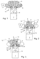
- Corresponding Fig. 1 has a device 15 a plurality of distance sensors 1 to 6, which are located in the direction of travel 14 located on the front of a motor vehicle 7.
- the device 15 is designed to detect a current distance A between the motor vehicle 7 and an obstacle 8.
- the number of in Fig. 1 shown distance sensors 1 to 6 is variable.
- further distance sensors, not shown are arranged in the rear direction of the motor vehicle 7 in the direction of travel 14.
- the distance sensors 1 to 6 each emit a radiation lobe which detects a variable detection area 9.
- the maximum extent of the detection area 9 is characterized by a range R max . All distance sensors 1 to 6 are connected via unspecified connection lines with a control unit 10, which is able to control the range R of the individual detection areas 9 independently or adapt.
- the control unit 10 for calculating a from the motor vehicle in the future traversed driving tube 11 based on dynamic vehicle data, such as the vehicle speed or the direction of travel 14, and static vehicle data, such as a constructive vehicle contour, and adapted to adapt the detection areas 9 of the distance sensors 1 to 6 to the calculated driving tube 11. Additionally or alternatively, the control unit 10, for example by means of a software-technical restriction, hide detected but not relevant obstacles 8.
- Fig. 2 the inventive device 15 is shown in the activated state when driving straight ahead of the motor vehicle 7.
- the control unit 10 calculates the driving hose 11, which in the future will be traversed by the motor vehicle 7, which lies between the two lateral boundaries 12 and 13 in the direction of travel in front of the motor vehicle 7.
- the control unit 10 controls the range R of the detection areas 9 of the individual distance sensors 1 to 6 in dependence of the two Limits 12 and 13, wherein the distance sensors 3 and 4, the detection areas 9 are completely in the driving tube 11, so controlled by the control unit 10 that they work with maximum range R max , whereas the distance sensors 1,2 and 5,6 of such the control unit 10 are driven so that their detection range 9 'lie substantially within the driving tube 11 and are limited by the lateral boundaries 12 and 13 in their extension.
- the illustrated obstacle 8, which lies outside the driving tube 11 is thus in contrast to Fig. 1 not detected by the distance sensor 1.
- the obstacle 8 located outside the driving tube 11 it is possible for the obstacle 8 located outside the driving tube 11 to be detected, but to be classified as a non-relevant obstacle 8 by the control unit 10 and to be blanked out.
- the device 15 according to the invention is also shown in the activated state, but when cornering.
- the two distance sensors 2 and 3 have their maximum range R max , whereas the distance sensors 1, 4, 5 and 6 are limited in their range R '.
- the control unit 10 calculates here on the basis of the static and dynamic vehicle data, during cornering, in particular on the basis of the steering angle, the future of the motor vehicle 7 to be traveled by driving tube 11 and adjusts the range R 'to the lateral limits 12 and 13 of the driving tube 11.
- the object or obstacle 8 located outside the driving tube 11 is moved according to Fig. 3 from the reduced range R 'of the distance sensor 4 is not detected or registered.
- the relevant obstacle 8 ' which in the future traversed by the vehicle 7 driving tube 11 is detected by the distance sensor 2.
- the control unit 10 is connected to a braking device, not shown, of the motor vehicle 7 and effected by an emitted from the control unit 10 control signal automatic braking of the motor vehicle 7.
- a braking device not shown
- the distance sensors 1 to 6 can be designed as sensors with different measuring methods, for example as ultrasound, radar or optical sensors and be arranged on a vehicle front and / or on a vehicle rear.
- the adaptation of the detection areas 9 by the control unit 10 is dynamically based on the current vehicle data, such as vehicle speed, direction 14, vehicle acceleration, steering angle change, sensor function or measurement method.
- the invention provides for a control unit 10 of a device 15 for detecting a current distance A of a motor vehicle 7 from an obstacle 8, 8 'in such a way that it can calculate a driving tube 11 passing through from the vehicle 7 on the basis of static and dynamic vehicle data and also in FIG is able to relevant obstacles 8 ', which are within the driving tube 11, and non-relevant obstacles 8, which are outside the driving tube 11 to distinguish.
- the calculation of the driving tube 11 thus ensures a precise differentiation between relevant and non-relevant objects or obstacles 8 and 8 ', whereby an increase in driving safety can be achieved.
- the detection range 9 is completely in the driving tube 11 are controlled by the control unit 10 so that they work with maximum range R max . This offers the advantage that the obstacles 8 'located in this area are detected early.
- control unit 10 may be connected to a braking device of the motor vehicle 7 and be designed to automatically decelerate the motor vehicle 7. Detects a distance sensor 1 to 6 located in the route 11 and thus relevant obstacle 8 ', so he reports this to the control unit 10, which automatically decelerates the motor vehicle 7 and thereby reduces a risk of collision.
- the distance sensors 1 to 6 can be arranged either on a vehicle front and / or on a vehicle rear.
Landscapes
- Engineering & Computer Science (AREA)
- Radar, Positioning & Navigation (AREA)
- Remote Sensing (AREA)
- Mechanical Engineering (AREA)
- Physics & Mathematics (AREA)
- Transportation (AREA)
- Chemical & Material Sciences (AREA)
- Electromagnetism (AREA)
- Combustion & Propulsion (AREA)
- Computer Networks & Wireless Communication (AREA)
- General Physics & Mathematics (AREA)
- Control Of Position, Course, Altitude, Or Attitude Of Moving Bodies (AREA)
- Measurement Of Velocity Or Position Using Acoustic Or Ultrasonic Waves (AREA)
- Control Of Driving Devices And Active Controlling Of Vehicle (AREA)
- Regulating Braking Force (AREA)
- Traffic Control Systems (AREA)
Abstract
Claims (13)
- Dispositif (15) de détection de l'écart momentané (A) entre un véhicule automobile (7) et un obstacle (8, 8'), comprenant des détecteurs d'écart (1-6) et une unité de commande (10), l'unité de commande (10) étant configurée pour calculer une trajectoire de déplacement (11) qui sera ultérieurement parcourue par le véhicule automobile (7) au moyen de données statiques et dynamiques du véhicule automobile et l'unité de commande (10) étant configurée pour différencier les obstacles pertinents (8'), qui se trouvent à l'intérieur de la trajectoire de déplacement (11), et les obstacles non pertinents (8) qui se trouvent en dehors de la trajectoire de déplacement (11), caractérisé en ce que les détecteurs d'écart (1-6) présentent respectivement une zone de détection variable (9), que l'unité de commande (10) est configurée pour adapter la portée (R) des zones de détection (9) des détecteurs d'écart (1-6) aux limites latérales (12, 13) de la trajectoire de déplacement (11) et que ces détecteurs d'écart (1-6) dont la zone de détection (9) se trouve entièrement dans la trajectoire de déplacement (11) sont commandés par l'unité de commande (10) de telle sorte qu'ils fonctionnent avec la portée maximale (Rmax).
- Dispositif selon la revendication 1, caractérisé en ce que l'unité de commande (10) est configurée pour masquer les obstacles non pertinents (8) détectés.
- Dispositif selon l'une des revendications 1 à 2, caractérisé en ce que l'unité de commande (10) est reliée avec un dispositif de freinage du véhicule automobile (7) et elle est configurée pour freiner automatiquement le véhicule automobile (7).
- Dispositif selon l'une des revendications 1 à 3, caractérisé en ce que les détecteurs d'écart (1-6) sont réalisés sous la forme de détecteurs à ultrasons et/ou de détecteurs radar et/ou de détecteurs optiques.
- Dispositif selon l'une des revendications 1 à 4, caractérisé en ce que les détecteurs d'écart (1-6) sont montés sur un avant du véhicule et/ou sur un arrière du véhicule.
- Dispositif selon l'une des revendications 1 à 5, caractérisé en ce qu'au moins un élément du groupe suivant est utilisé comme données dynamiques du véhicule : vitesse du véhicule, sens de déplacement, accélération du véhicule, angle de braquage, modification de l'angle de braquage, fonctionnement du détecteur.
- Dispositif selon l'une des revendications 1 à 6, caractérisé en ce qu'au moins un contour du véhicule est utilisé comme données statiques du véhicule.
- Procédé de détection d'un écart momentané (A) entre un véhicule automobile (7) et un obstacle (8, 8'), comprenant des détecteurs d'écart (1-6) et une unité de commande (10), l'unité de commande (10) calculant une trajectoire de déplacement (11) qui sera ultérieurement parcourue par le véhicule automobile (7) au moyen de données statiques et dynamiques du véhicule automobile et faisant la différence entre les obstacles pertinents (8') qui se trouvent à l'intérieur de la trajectoire de déplacement (11) et les obstacles non pertinents (8) qui se trouvent en dehors de la trajectoire de déplacement (11), caractérisé en ce que l'unité de commande (10) commande la portée (R) des zones de détection (9) des détecteurs d'écart (1 à 6) individuels de telle sorte que les détecteurs d'écart (3 et 4), dont les zones de détection (9) se trouvent entièrement dans la trajectoire de déplacement (11), fonctionnent avec la portée maximale (Rmax), alors que les autres détecteurs d'écart (1, 2 et 5, 6) sont commandés de manière s'écartant de leur portée maximale (Rmax) de sorte que leur zone de détection (9') se trouve pour l'essentiel à l'intérieur de la trajectoire de déplacement (11).
- Procédé selon la revendication 8, caractérisé en ce que les détecteurs d'écart (1-6) présentent respectivement une zone de détection (9) variable, que l'unité de commande (10) adapte la portée (R) des zones de détection (9) des détecteurs d'écart (1-6) aux limites latérales (12, 13) de la trajectoire de déplacement (11).
- Procédé selon la revendication 8 ou 9, caractérisé en ce que l'unité de commande (10) masque les obstacles non pertinents (8) détectés.
- Procédé selon l'une des revendications 8 à 10, caractérisé en ce que l'unité de commande (10) est reliée avec un dispositif de freinage du véhicule automobile (7) et le véhicule automobile (7) freine automatiquement sur un signal de commande de l'unité de commande (10).
- Procédé selon l'une des revendications 8 à 11, caractérisé en ce que les détecteurs d'écart (1-6) fonctionnent avec un principe de mesure basé sur des ondes électromagnétiques ou sur des ondes sonores.
- Procédé selon l'une des revendications 8 à 12, caractérisé en ce qu'au moins un élément du groupe suivant est utilisé pour calculer la trajectoire de déplacement (11) : vitesse du véhicule, sens de déplacement, accélération du véhicule, angle de braquage, modification de l'angle de braquage, fonctionnement du détecteur, contour du véhicule.
Applications Claiming Priority (2)
| Application Number | Priority Date | Filing Date | Title |
|---|---|---|---|
| DE10341128A DE10341128A1 (de) | 2003-09-06 | 2003-09-06 | Vorrichtung und Verfahren zur Erfassung eines momentanen Abstandes eines Kraftfahrzeugs von einem Hindernis |
| PCT/EP2004/009382 WO2005023613A1 (fr) | 2003-09-06 | 2004-08-21 | Procede et dispositif pour saisir la distance momentanee separant un vehicule d'un obstacle |
Publications (2)
| Publication Number | Publication Date |
|---|---|
| EP1660362A1 EP1660362A1 (fr) | 2006-05-31 |
| EP1660362B1 true EP1660362B1 (fr) | 2008-04-23 |
Family
ID=34223406
Family Applications (1)
| Application Number | Title | Priority Date | Filing Date |
|---|---|---|---|
| EP04764364A Expired - Lifetime EP1660362B1 (fr) | 2003-09-06 | 2004-08-21 | Procede et dispositif pour saisir la distance momentanee separant un vehicule d'un obstacle |
Country Status (5)
| Country | Link |
|---|---|
| US (1) | US20070273490A1 (fr) |
| EP (1) | EP1660362B1 (fr) |
| JP (1) | JP2007504543A (fr) |
| DE (2) | DE10341128A1 (fr) |
| WO (1) | WO2005023613A1 (fr) |
Cited By (2)
| Publication number | Priority date | Publication date | Assignee | Title |
|---|---|---|---|---|
| DE102010023164A1 (de) | 2010-06-09 | 2011-12-15 | Valeo Schalter Und Sensoren Gmbh | Verfahren zum Warnen eines Fahrers eines Kraftfahrzeugs vor der Anwesenheit eines Objektes in der Umgebung, Fahrerassistenzsystem und Kraftfahrzeug |
| WO2012045323A1 (fr) | 2010-10-07 | 2012-04-12 | Connaught Electronics Ltd. | Procédé et système d'assistance au conducteur pour avertir un conducteur d'un véhicule à moteur de la présence d'un obstacle dans un environnement du véhicule à moteur |
Families Citing this family (30)
| Publication number | Priority date | Publication date | Assignee | Title |
|---|---|---|---|---|
| EP1853937A2 (fr) * | 2005-02-10 | 2007-11-14 | Systems Laboratory Inc. Automotive | Systeme radar d'automobile avec faisceau de veille |
| DE102005024492A1 (de) * | 2005-05-27 | 2006-11-30 | Daimlerchrysler Ag | Einparkhilfe für ein Kraftfahrzeug |
| US7324407B2 (en) | 2005-07-08 | 2008-01-29 | Valeo Switches And Detection Systems | Prevention of reporting unwanted signals by the filtering of sensor data |
| DE102005039525A1 (de) * | 2005-08-18 | 2007-02-22 | Daimlerchrysler Ag | Verfahren zur Bestimmung eines Fahrschlauchs innerhalb dem sich ein Fahrzeug mit großer Wahrscheinlichkeit fortbewegt |
| JP5016889B2 (ja) * | 2006-10-11 | 2012-09-05 | 日立オートモティブシステムズ株式会社 | 予防安全装置 |
| US7567168B2 (en) * | 2006-10-24 | 2009-07-28 | Shih-Hsiung Li | Car reversal radar that automatically modifies the sensor scanning range and method of the same |
| DE102006057751A1 (de) * | 2006-12-07 | 2008-06-12 | Siemens Ag | Verfahren zur Kollisionsvermeidung von Fahrzeugen mit Objekten |
| JP4613906B2 (ja) | 2006-12-14 | 2011-01-19 | トヨタ自動車株式会社 | 車両用周辺監視装置 |
| US7830243B2 (en) * | 2007-02-02 | 2010-11-09 | Chrysler Group Llc | Dual mode vehicle blind spot system |
| DE102007036787A1 (de) * | 2007-08-03 | 2009-02-05 | Robert Bosch Gmbh | Abstandsregler mit automatischer Anhaltefunktion |
| JP2009198402A (ja) * | 2008-02-22 | 2009-09-03 | Toyota Motor Corp | 衝突検出装置 |
| DE102008011228B4 (de) | 2008-02-26 | 2026-01-22 | Robert Bosch Gmbh | Verfahren zur Unterstützung eines Nutzers eines Fahrzeugs, Steuereinrichtung für ein Fahrerassistenzsystem eines Fahrzeugs und Fahrzeug mit einer derartigen Steuereinrichtung |
| DE102008060684B4 (de) | 2008-03-28 | 2019-05-23 | Volkswagen Ag | Verfahren und Vorrichtung zum automatischen Einparken eines Kraftfahrzeugs |
| FR2941537B1 (fr) * | 2009-01-29 | 2016-02-05 | Valeo Vision Sas | Procede de surveillance de l'environnement d'un vehicule automobile |
| DE102009047066A1 (de) * | 2009-11-24 | 2011-05-26 | Robert Bosch Gmbh | Verfahren zur Warnung vor einem Objekt in der Umgebung eines Fahrzeugs sowie Fahrassistentensystem |
| ATE545045T1 (de) | 2009-12-17 | 2012-02-15 | Sick Ag | Optoelektronischer sensor |
| WO2012090114A1 (fr) * | 2010-12-26 | 2012-07-05 | Yissum Research Development Company Of The Hebrew University Of Jerusalem Ltd. | Dispositifs à base d'infrarouges pour guider des personnes aveugles et mal-voyantes |
| US8872641B2 (en) | 2011-05-27 | 2014-10-28 | Headup Systems | Premises-based wireless alert system for automotive tall cargo |
| US9415774B2 (en) * | 2011-09-22 | 2016-08-16 | Nissan Motor Co., Ltd. | Vehicle control apparatus including an obstacle detection device |
| KR101316501B1 (ko) * | 2011-10-14 | 2013-10-10 | 현대자동차주식회사 | 메쉬형 공간 해석기법을 이용한 주차 공간 탐지방법 및 그 시스템 |
| EP2816539B1 (fr) * | 2012-02-14 | 2018-07-11 | Nissan Motor Co., Ltd. | Dispositif de commande de déplacement et procédé de commande de déplacement |
| JP6123133B2 (ja) * | 2013-03-04 | 2017-05-10 | パナソニックIpマネジメント株式会社 | 車両用障害物検知装置および、車両用障害物検知システム |
| DE202013006676U1 (de) | 2013-07-25 | 2014-10-28 | GM Global Technology Operations LLC (n. d. Ges. d. Staates Delaware) | System zur Warnung vor einer möglichen Kollision einesKraftfahrzeuges mit einem Objekt |
| DE102013217486B4 (de) * | 2013-09-03 | 2026-03-19 | Aumovio Autonomous Mobility Germany Gmbh | Verfahren zur Repräsentation eines Umfelds eines Fahrzeugs in einem Belegungsgitter |
| JP6413240B2 (ja) * | 2014-01-08 | 2018-10-31 | 株式会社デンソー | 車両制御装置および車両 |
| US9983300B2 (en) * | 2014-10-17 | 2018-05-29 | Qualcomm Incorporated | Systems, methods, and apparatus for living object protection in wireless power transfer applications |
| DE102015220643A1 (de) * | 2015-10-22 | 2017-04-27 | Robert Bosch Gmbh | Verfahren und Vorrichtung zum Verringern eines Kollisionsrisikos einer Kollision eines Kraftfahrzeugs mit einem Objekt |
| DE102019216185A1 (de) * | 2019-10-21 | 2021-04-22 | Robert Bosch Gmbh | Verfahren zur Verifikation und Anpassung eines Fahrbereichs zum Befahren mit autonomen Arbeitsmaschinen |
| DE102020102513B4 (de) | 2020-01-31 | 2022-07-07 | Eisenmann Gmbh | Transportsystem zum Transportieren von Werkstücken und Verfahren zum Betreiben eines solchen Transportsystems |
| WO2026010410A1 (fr) * | 2024-07-04 | 2026-01-08 | 엘에스엠트론 주식회사 | Véhicule autonome et procédé de détection d'objet associé |
Family Cites Families (15)
| Publication number | Priority date | Publication date | Assignee | Title |
|---|---|---|---|---|
| DE3830790A1 (de) * | 1988-09-09 | 1990-03-15 | Freund Eckhard | Verfahren und vorrichtung zur automatischen kollisionsvermeidung fuer automatisch fuehrbare fahrzeuge |
| DE4407757A1 (de) * | 1993-03-08 | 1994-09-15 | Mazda Motor | Vorrichtung zur Erfassung von Hindernissen für ein Fahrzeug |
| DE4317960A1 (de) * | 1993-05-28 | 1995-01-12 | Bayerische Motoren Werke Ag | Verfahren zum Vermeiden einer Kollision eines Kraftfahrzeugs |
| DE4333357A1 (de) * | 1993-09-30 | 1995-04-06 | Bosch Gmbh Robert | Einparkhilfe mit Radsensor |
| JP3522317B2 (ja) * | 1993-12-27 | 2004-04-26 | 富士重工業株式会社 | 車輌用走行案内装置 |
| US5745870A (en) * | 1994-09-14 | 1998-04-28 | Mazda Motor Corporation | Traveling-path prediction apparatus and method for vehicles |
| US5689264A (en) * | 1994-10-05 | 1997-11-18 | Mazda Motor Corporation | Obstacle detecting system for vehicles |
| DE19507957C1 (de) * | 1995-03-07 | 1996-09-12 | Daimler Benz Ag | Fahrzeug mit optischer Abtasteinrichtung für einen seitlichen Fahrbahnbereich |
| DE19655360B4 (de) * | 1996-11-04 | 2010-12-09 | Valeo Schalter Und Sensoren Gmbh | Verfahren und Abstandsmesseinrichtung zur von den Fahrzeugdaten abhängigen Abstandsmessung von Hindernissen |
| JP2000075028A (ja) * | 1998-08-27 | 2000-03-14 | Toyota Motor Corp | 車載dbfレーダ装置 |
| DE19934670B4 (de) * | 1999-05-26 | 2004-07-08 | Robert Bosch Gmbh | Objektdetektionssystem |
| US6150932A (en) * | 1999-10-04 | 2000-11-21 | General Motors Corporation | Vehicle operator alert process |
| DE10149146A1 (de) * | 2001-10-05 | 2003-04-17 | Bosch Gmbh Robert | Geschwindigkeitsregler mit Abstandsregelfunktion |
| DE10160189B4 (de) * | 2001-12-07 | 2019-06-06 | Bayerische Motoren Werke Aktiengesellschaft | ACC-Fahrspurprädiktionsbreitenadaption abhängig von Navigationssystemdaten und Objektdaten |
| WO2003064215A1 (fr) * | 2002-01-28 | 2003-08-07 | Matsushita Electric Works, Ltd. | Systeme d'alarme et de detection d'obstacles pour vehicule |
-
2003
- 2003-09-06 DE DE10341128A patent/DE10341128A1/de not_active Withdrawn
-
2004
- 2004-08-21 JP JP2006525068A patent/JP2007504543A/ja not_active Abandoned
- 2004-08-21 US US10/570,800 patent/US20070273490A1/en not_active Abandoned
- 2004-08-21 WO PCT/EP2004/009382 patent/WO2005023613A1/fr not_active Ceased
- 2004-08-21 DE DE502004006940T patent/DE502004006940D1/de not_active Expired - Fee Related
- 2004-08-21 EP EP04764364A patent/EP1660362B1/fr not_active Expired - Lifetime
Cited By (2)
| Publication number | Priority date | Publication date | Assignee | Title |
|---|---|---|---|---|
| DE102010023164A1 (de) | 2010-06-09 | 2011-12-15 | Valeo Schalter Und Sensoren Gmbh | Verfahren zum Warnen eines Fahrers eines Kraftfahrzeugs vor der Anwesenheit eines Objektes in der Umgebung, Fahrerassistenzsystem und Kraftfahrzeug |
| WO2012045323A1 (fr) | 2010-10-07 | 2012-04-12 | Connaught Electronics Ltd. | Procédé et système d'assistance au conducteur pour avertir un conducteur d'un véhicule à moteur de la présence d'un obstacle dans un environnement du véhicule à moteur |
Also Published As
| Publication number | Publication date |
|---|---|
| JP2007504543A (ja) | 2007-03-01 |
| WO2005023613A1 (fr) | 2005-03-17 |
| DE502004006940D1 (de) | 2008-06-05 |
| DE10341128A1 (de) | 2005-03-31 |
| US20070273490A1 (en) | 2007-11-29 |
| EP1660362A1 (fr) | 2006-05-31 |
Similar Documents
| Publication | Publication Date | Title |
|---|---|---|
| EP1660362B1 (fr) | Procede et dispositif pour saisir la distance momentanee separant un vehicule d'un obstacle | |
| EP2051875B1 (fr) | Dispositif pour la saisie d'un objet en déplacement | |
| EP2089266B1 (fr) | Système d'aide au stationnement avec fonction de stationnement en bataille améliorée | |
| EP1685001B1 (fr) | Dispositif pour detecter des objets en mouvement | |
| EP0993990B1 (fr) | Système d'aide pour se garer | |
| EP1904352B1 (fr) | Procede et systeme pour aider un conducteur de vehicule automobile a identifier des emplacements de stationnement libres destines audit vehicule | |
| EP2504827A1 (fr) | Procédé d'avertissement concernant l'existence d'un objet dans l'environnement d'un véhicule et système d'aide à la conduite | |
| EP1947476A2 (fr) | Procédé destiné à assister un processus de stationnement d'un véhicule | |
| DE102006002232B4 (de) | Anfahrwarner mit Kollisionsmelder bei Nutzfahrzeug | |
| EP1614585B1 (fr) | Méthode et dispositif de mesure d'un emplacement de stationnement pour un système d'assistance au stationnement d'un véhicule automobile | |
| EP1873737B1 (fr) | Procédé destiné à la détection d'une situation critique devant un véhicule | |
| DE102014202752B4 (de) | Erkennung dynamischer Objekte mittels Ultraschall | |
| EP2781421A2 (fr) | Suppression des perturbations dans la surveillance de l'angle mort | |
| EP2087478B1 (fr) | Procédé pour éviter les collisions de véhicules avec des objets | |
| WO2016071191A1 (fr) | Procédé de fonctionnement d'un système d'aide à la conduite d'un véhicule automobile, système d'aide à la conduite et véhicule automobile | |
| EP1801613B1 (fr) | Procédé et dispositif destinés à la détection d'objets dans l'environnement d'un véhicule | |
| DE10307229A1 (de) | Vorrichtung und Verfahren zur Überwachung des Nahbereichs eines Kraftfahrzeuges zur Vermeidung von Kollisionen | |
| DE102006002662A1 (de) | Sicherheitseinrichtung für ein Fahrzeug und Verfahren zum Betrieb einer Sicherheitseinrichtung | |
| EP1361459A1 (fr) | Système d'assistance de conducteur avec navigation a l'estimé | |
| WO2020108937A1 (fr) | Procédé pour pronostiquer un changement de voie de circulation prématuré, système d'aide à la conduite, véhicule à moteur et produit-programme d'ordinateur | |
| EP3093689A1 (fr) | Procede de fonctionnement d'un systeme d'assistance au conducteur d'un vehicule automobile comprenant une reconnaissance d'objet a proximite, systeme d'assistance au conducteur et vehicule automobile | |
| EP3363705B1 (fr) | Procédé d'activation d'au moins une fonction d'un véhicule automobile, système d'aide à la conduite et véhicule automobile | |
| DE102010063944A1 (de) | Verfahren zur Erfassung von Objekten | |
| EP3465265B1 (fr) | Procédé de fonctionnement d'un dispositif de détection par ultrasons d'un véhicule automobile par transmission de données de configuration, dispositif de détection par ultrasons ainsi que véhicule automobile |
Legal Events
| Date | Code | Title | Description |
|---|---|---|---|
| PUAI | Public reference made under article 153(3) epc to a published international application that has entered the european phase |
Free format text: ORIGINAL CODE: 0009012 |
|
| 17P | Request for examination filed |
Effective date: 20060303 |
|
| AK | Designated contracting states |
Kind code of ref document: A1 Designated state(s): DE FR GB |
|
| DAX | Request for extension of the european patent (deleted) | ||
| RBV | Designated contracting states (corrected) |
Designated state(s): DE FR GB |
|
| RAP1 | Party data changed (applicant data changed or rights of an application transferred) |
Owner name: DAIMLERCHRYSLER AG |
|
| GRAP | Despatch of communication of intention to grant a patent |
Free format text: ORIGINAL CODE: EPIDOSNIGR1 |
|
| RAP1 | Party data changed (applicant data changed or rights of an application transferred) |
Owner name: DAIMLER AG |
|
| GRAS | Grant fee paid |
Free format text: ORIGINAL CODE: EPIDOSNIGR3 |
|
| GRAA | (expected) grant |
Free format text: ORIGINAL CODE: 0009210 |
|
| AK | Designated contracting states |
Kind code of ref document: B1 Designated state(s): DE FR GB |
|
| REG | Reference to a national code |
Ref country code: GB Ref legal event code: FG4D Free format text: NOT ENGLISH |
|
| REF | Corresponds to: |
Ref document number: 502004006940 Country of ref document: DE Date of ref document: 20080605 Kind code of ref document: P |
|
| PGFP | Annual fee paid to national office [announced via postgrant information from national office to epo] |
Ref country code: DE Payment date: 20080822 Year of fee payment: 5 |
|
| EN | Fr: translation not filed | ||
| PLBE | No opposition filed within time limit |
Free format text: ORIGINAL CODE: 0009261 |
|
| STAA | Information on the status of an ep patent application or granted ep patent |
Free format text: STATUS: NO OPPOSITION FILED WITHIN TIME LIMIT |
|
| 26N | No opposition filed |
Effective date: 20090126 |
|
| GBPC | Gb: european patent ceased through non-payment of renewal fee |
Effective date: 20080821 |
|
| PG25 | Lapsed in a contracting state [announced via postgrant information from national office to epo] |
Ref country code: FR Free format text: LAPSE BECAUSE OF FAILURE TO SUBMIT A TRANSLATION OF THE DESCRIPTION OR TO PAY THE FEE WITHIN THE PRESCRIBED TIME-LIMIT Effective date: 20090227 |
|
| PG25 | Lapsed in a contracting state [announced via postgrant information from national office to epo] |
Ref country code: GB Free format text: LAPSE BECAUSE OF NON-PAYMENT OF DUE FEES Effective date: 20080821 |
|
| PG25 | Lapsed in a contracting state [announced via postgrant information from national office to epo] |
Ref country code: DE Free format text: LAPSE BECAUSE OF NON-PAYMENT OF DUE FEES Effective date: 20100302 |