EP3465265B1 - Procédé de fonctionnement d'un dispositif de détection par ultrasons d'un véhicule automobile par transmission de données de configuration, dispositif de détection par ultrasons ainsi que véhicule automobile - Google Patents
Procédé de fonctionnement d'un dispositif de détection par ultrasons d'un véhicule automobile par transmission de données de configuration, dispositif de détection par ultrasons ainsi que véhicule automobile Download PDFInfo
- Publication number
- EP3465265B1 EP3465265B1 EP17726896.8A EP17726896A EP3465265B1 EP 3465265 B1 EP3465265 B1 EP 3465265B1 EP 17726896 A EP17726896 A EP 17726896A EP 3465265 B1 EP3465265 B1 EP 3465265B1
- Authority
- EP
- European Patent Office
- Prior art keywords
- motor vehicle
- ultrasonic sensor
- ultrasonic
- detected
- sensor
- Prior art date
- Legal status (The legal status is an assumption and is not a legal conclusion. Google has not performed a legal analysis and makes no representation as to the accuracy of the status listed.)
- Active
Links
Images

Classifications
-
- G—PHYSICS
- G01—MEASURING; TESTING
- G01S—RADIO DIRECTION-FINDING; RADIO NAVIGATION; DETERMINING DISTANCE OR VELOCITY BY USE OF RADIO WAVES; LOCATING OR PRESENCE-DETECTING BY USE OF THE REFLECTION OR RERADIATION OF RADIO WAVES; ANALOGOUS ARRANGEMENTS USING OTHER WAVES
- G01S15/00—Systems using the reflection or reradiation of acoustic waves, e.g. sonar systems
- G01S15/88—Sonar systems specially adapted for specific applications
- G01S15/93—Sonar systems specially adapted for specific applications for anti-collision purposes
- G01S15/931—Sonar systems specially adapted for specific applications for anti-collision purposes of land vehicles
-
- G—PHYSICS
- G01—MEASURING; TESTING
- G01S—RADIO DIRECTION-FINDING; RADIO NAVIGATION; DETERMINING DISTANCE OR VELOCITY BY USE OF RADIO WAVES; LOCATING OR PRESENCE-DETECTING BY USE OF THE REFLECTION OR RERADIATION OF RADIO WAVES; ANALOGOUS ARRANGEMENTS USING OTHER WAVES
- G01S7/00—Details of systems according to groups G01S13/00, G01S15/00, G01S17/00
- G01S7/003—Transmission of data between radar, sonar or lidar systems and remote stations
-
- G—PHYSICS
- G01—MEASURING; TESTING
- G01S—RADIO DIRECTION-FINDING; RADIO NAVIGATION; DETERMINING DISTANCE OR VELOCITY BY USE OF RADIO WAVES; LOCATING OR PRESENCE-DETECTING BY USE OF THE REFLECTION OR RERADIATION OF RADIO WAVES; ANALOGOUS ARRANGEMENTS USING OTHER WAVES
- G01S7/00—Details of systems according to groups G01S13/00, G01S15/00, G01S17/00
- G01S7/52—Details of systems according to groups G01S13/00, G01S15/00, G01S17/00 of systems according to group G01S15/00
- G01S7/52004—Means for monitoring or calibrating
Definitions
- the present invention relates to a method for operating an ultrasonic sensor device of a motor vehicle, in which sensor data is received from a plurality of ultrasonic sensors by means of a control device in order to detect an environment of the motor vehicle, and configuration data is transmitted to the respective ultrasonic sensors by means of the control device in order to configure the ultrasonic sensors.
- the present invention relates to an ultrasonic sensor device for a motor vehicle.
- the present invention relates to a motor vehicle.
- ultrasonic sensor devices for motor vehicles.
- Such an ultrasonic sensor device can comprise a plurality of ultrasonic sensors, which can be arranged distributed on the motor vehicle, for example.
- These ultrasonic sensors can be used to provide sensor data that describe the surroundings of the motor vehicle and in particular objects in the surroundings of the motor vehicle.
- the sensor data provided by the ultrasonic sensors can be evaluated using a corresponding control device. This allows objects in the surroundings of the motor vehicle to be detected and the distance between the motor vehicle and the respective objects to be determined. This information can then be used to move the motor vehicle past the object without collision.
- other collision-avoiding measures such as emergency braking, can be carried out.
- the respective ultrasonic sensors can be configured accordingly using the control device of the ultrasonic sensor device. It is known that current ultrasonic sensors contain corresponding circuits or evaluation units that carry out a certain amount of signal processing. In order to parameterize or query these circuits, corresponding configuration data is sent to the ultrasonic sensors. With the help of the configuration data, the respective ultrasonic sensors can be adapted to the ambient conditions, such as temperature or humidity.
- the EP 1 624 319 A1 a method for measuring the distance of an obstacle in the vicinity of the motor vehicle using an echo method.
- a transmission signal is emitted by a sensor device provided on the motor vehicle and the echo signal reflected by the obstacle is received by the sensor device.
- a relative ratio between the distance-dependent echo amplitude of the echo signal and a threshold value of the sensor device determining the detection of the received echo signal is adapted to the measured environmental conditions of the motor vehicle.
- the configuration data is usually transmitted from the control device to the respective ultrasonic sensors using a slow transmission protocol. Furthermore, it is usually provided that the ultrasonic sensors only have one data line, so that either only the configuration data from the control device to the ultrasonic sensor or the sensor data from the ultrasonic sensor to the control device can be transmitted.
- the disadvantage here is that no objects in the vicinity of the motor vehicle can be detected during the transmission of the configuration data. This can also mean that, for example, no warning can be issued if the distance between the motor vehicle and the object falls below a minimum distance. In the worst case, this can lead to an unwanted collision between the motor vehicle and the object.
- the configuration data is only transmitted when the vehicle is stationary. If the ultrasonic sensor device is used in the area of parking aids, this only brings with it a minor disadvantage, since the vehicle is usually stopped at the beginning of a parking process, which enables the configuration or reprogramming of the ultrasonic sensors. If the ultrasonic sensor device is used for other applications, for example for blind spot monitoring, it is usually intended that the ultrasonic sensors should be operational for a long period of time without the vehicle coming to a standstill in the meantime. Reconfiguration or reparameterization of the ultrasonic sensors is necessary, particularly for longer motorway journeys where temperature changes occur.
- the DE 10 2013 211 419 A1 discloses a method for operating an ultrasonic sensor in which a heating mode is used to raise the temperature of the membrane above a freezing temperature.
- An ultrasonic sensor device which has an adjustment device for automatically readjusting the ultrasonic sensor device.
- sensor data is received from a plurality of ultrasonic sensors, preferably by means of a control device, in order to detect the surroundings of the motor vehicle.
- configuration data is preferably transmitted to the respective ultrasonic sensors, preferably by means of the control device, in order to configure the ultrasonic sensors.
- the configuration data is preferably transmitted to the respective ultrasonic sensor if it is in the non-detection mode.
- a method according to the invention is used to operate an ultrasonic sensor device of a motor vehicle.
- sensor data is received from a plurality of ultrasonic sensors by means of a control device.
- configuration data is transmitted to the respective ultrasonic sensors by means of the control device in order to configure the ultrasonic sensors.
- the ultrasonic sensors it is detected whether the ultrasonic sensor is in a detection mode in which the sensor data of the ultrasonic sensor is used to detect the surroundings, or in a non-detection mode in which the sensor data of the ultrasonic sensor is not taken into account for detecting the surroundings, wherein the configuration data is transmitted to the respective ultrasonic sensor if it is in the non-detection mode.
- the method is intended to operate an ultrasonic sensor device of a motor vehicle.
- This ultrasonic sensor device can have a control device, which can be formed, for example, by an electronic control unit of the motor vehicle.
- the ultrasonic sensor device can have a plurality of ultrasonic sensors, which can be arranged distributed on the motor vehicle, for example.
- the ultrasonic sensor device can be used to detect or monitor the surroundings of the motor vehicle. In particular, objects or obstacles in the surroundings of the motor vehicle can be detected.
- ultrasonic signals can be emitted with the respective ultrasonic sensors and the ultrasonic signals reflected by the object can be received again.
- the respective ultrasonic sensors can provide a sensor signal which describes the ultrasonic signal reflected by the object. The distance between the motor vehicle and the object can then be determined on the basis of the transit time between the emission of the ultrasonic signal and the reception of the ultrasonic signal reflected by the object.
- the ultrasonic sensor device can assist a driver of the motor vehicle in avoiding a collision between the motor vehicle and the object.
- the ultrasonic sensor device can be a driver assistance system or part of a driver assistance system.
- the ultrasonic sensor device can issue a corresponding warning if a minimum distance between the motor vehicle and the object is not reached.
- the ultrasonic sensor device can also be designed in the manner of a blind spot assistant and issue a corresponding warning to the driver of the motor vehicle if an object or a another vehicle is in the blind spot of the motor vehicle.
- the ultrasonic sensor device can also be used to carry out an appropriate intervention in the steering and/or braking system. For example, emergency braking can be carried out if there is a risk of a collision between the motor vehicle and the object.
- the control device is used to configure or adjust the respective ultrasonic sensors. Since the attenuation properties of the air in the environment, which serves as a transmitting medium for the ultrasonic signals, change significantly depending on the ambient conditions, it is necessary to configure the ultrasonic sensors depending on the ambient conditions, in particular temperature and/or humidity.
- the control device can be used to determine configuration data for the respective ultrasonic sensors and transmit this to the ultrasonic sensors.
- the respective ultrasonic sensors can have an evaluation unit or an electronic circuit that is used for signal processing. This evaluation unit can now receive the configuration data and change the settings of the ultrasonic sensor depending on the received configuration data.
- the detection mode describes the state of the ultrasonic sensor in which the sensor data provided by the ultrasonic sensor is used by the control device to detect or monitor the surroundings of the motor vehicle.
- the non-detection mode describes the state of the ultrasonic sensor in which the sensor data of the ultrasonic sensor are not taken into account by the control device when detecting the surroundings.
- the non-detection mode therefore describes a state in which the sensor data of the ultrasonic sensor are not currently required.
- the non-detection mode of the ultrasonic sensor can in particular describe a state in which no further information about the surroundings of the motor vehicle and in particular about an object in the surroundings of the motor vehicle can be obtained from the sensor signals of the ultrasonic sensor.
- the Configuration data is transferred to this ultrasonic sensor.
- sensor data cannot usually be transferred from the ultrasonic sensor to the control device.
- the ultrasonic sensor is in non-detection mode, however, there is no risk that objects in the environment with which a collision is imminent will not be detected during the transfer of configuration data, since this ultrasonic sensor is not currently needed to detect the environment or detect objects.
- the configuration data is transferred to the ultrasonic sensor precisely when it is not needed to detect the environment or detect objects. This means that the configuration data can be transferred not only when the motor vehicle is stationary, for example. This provides further options for reconfiguring the ultrasonic sensor and adapting it to the respective environmental conditions.
- the detection of whether the ultrasonic sensor is in the detection mode and in the non-detection mode is carried out while the motor vehicle is driving.
- the non-detection mode is detected during the issuing of a warning to a driver of the motor vehicle, the warning being issued as a result of the object in the environment being detected using the sensor data.
- the control device detects using the sensor data that, for example, a collision between the motor vehicle and the object may be imminent, a corresponding warning can be issued using the ultrasonic sensor device.
- This warning can be issued acoustically, optically and/or haptically using a corresponding output device, for example.
- An essential finding of the present invention is to use the time period during which the warning is given about the object to reconfigure the ultrasonic sensors. If an object is warned about using the ultrasonic sensor device, the ultrasonic sensor device has already reliably detected this object. If now the new configuration of the ultrasonic sensors is carried out, there is no risk that the warning will not be triggered because it is already active. In this case, the non-detection mode of the ultrasonic sensor will be detected as long as the warning is issued.
- the duration of a warning usually lasts between 0.5 seconds and 1 second.
- the transmission of the configuration data from the control device to the ultrasonic sensors usually lasts a few milliseconds and can last a maximum of 0.5 seconds.
- the non-detection mode for the ultrasonic sensors can be assumed while the warning is being issued and the configuration data can be transmitted. If the warning is issued, it can be provided in particular that the configuration data is transmitted to all ultrasonic sensors of the ultrasonic sensor device.
- the warning describes that the object is located in a blind spot of the motor vehicle.
- the ultrasonic sensor device when used to monitor the blind spot, the detection of the non-detection mode and the transmission of the configuration data during this non-detection mode is suitable.
- the ultrasonic sensor device is used for blind spot monitoring or is part of a driver assistance system for blind spot monitoring, the ultrasonic sensors are active for a relatively long period of time and it is necessary to adapt the ultrasonic sensors to the changing environmental conditions.
- the configuration data are transmitted immediately after the non-detection mode is detected.
- the configuration data can, for example, be transmitted precisely when an object has just entered the blind spot and the warning has been activated for a predetermined period of time.
- the warning describes that a distance between the motor vehicle and the object falls below a predetermined minimum distance.
- a distance between the motor vehicle and the object falls below a predetermined minimum distance.
- the ultrasonic sensor device is used for collision warning or is part of a driver assistance system for collision warning.
- the non-detection mode can be recognized when a warning is issued to the driver or when a Collision warning has been initiated.
- the ultrasonic sensors can be reliably adapted to the ambient conditions.
- the non-detection mode is detected when an intervention is made in a braking system and/or a steering system of the motor vehicle.
- the non-detection mode is detected if an emergency braking has been initiated using a driver assistance system of the motor vehicle or the ultrasonic sensor device.
- the intervention is carried out, the object as a result of which the intervention takes place has already been detected.
- a reconfiguration of ultrasonic sensors can also be carried out in this case.
- an impending steering movement of the motor vehicle is detected and the non-detection mode is recognized if the impending steering movement is detected in a direction away from the detection range of the ultrasonic sensor.
- the impending steering movement can be detected, for example, by activation of a direction indicator or a blinker.
- the ultrasonic sensor device can receive a corresponding signal from a sensor which detects the activation of the direction indicator. If, for example, the blinker is set in a certain direction, the ultrasonic sensors on the opposite side can be reconfigured. In particular, the ultrasonic sensors whose installation position is opposite the impending steering direction can be reconfigured.
- the ultrasonic sensors on the left side of the motor vehicle can be reconfigured if it is detected that a steering movement to the right will occur. This takes into account that it is unlikely that the driver will need object detection or a warning on one side of the motor vehicle if he wants to drive in the other or opposite direction.
- a steering movement of the motor vehicle is detected and the non-detection mode is recognized if the steering movement is detected in a direction away from the detection range of the ultrasonic sensor.
- a steering movement that is currently being performed or has begun can also be detected.
- the control device can, for example, receive corresponding data from a steering angle sensor or a rotation rate sensor of the vehicle. In this case, too, the ultrasonic sensors on the side facing away from the steering movement can be reconfigured.
- a current direction of movement of the motor vehicle is detected and the non-detection mode is recognized if the detected direction of movement is facing away from the detection range of the ultrasonic sensor.
- the ultrasonic sensors arranged at the rear of the motor vehicle can be reconfigured. It can be provided that the ultrasonic sensors whose installation position is arranged on a side facing away from the direction of travel are reconfigured. It can be provided, for example, that these ultrasonic sensors are reconfigured simultaneously or one after the other.
- the non-detection mode is detected if the object is detected with at least one further ultrasonic sensor of the ultrasonic sensor device. If, for example, the object in the surroundings of the motor vehicle is detected with several ultrasonic sensors of the motor vehicle, it can be provided that at least one of these sensors is currently not being used for detecting this object and is reconfigured. This is the case, for example, if an object is located in front of a bumper of the motor vehicle, in which several ultrasonic sensors are usually arranged next to one another. It can also be taken into account that the ultrasonic sensors are typically not controlled simultaneously, but individually or in logical groups. In pauses in which the sensors neither emit ultrasonic signals nor receive reflected ultrasonic signals, they can be reconfigured.
- the configuration data are determined by means of the control device depending on a current temperature and/or air humidity in the environment of the motor vehicle.
- the control device can record corresponding data from a temperature sensor and a humidity sensor and use this to determine the configuration data for the ultrasonic sensors.
- This configuration data can then be transmitted to the ultrasonic sensors in order to adapt their operation to the temperature and/or air humidity or the resulting airborne sound attenuation.
- corresponding threshold curves can be adapted in the ultrasonic sensors or their evaluation units.
- the Sensitivity of the ultrasonic sensors can be adjusted depending on the configuration data.
- the ultrasonic sensor device for a motor vehicle is designed to carry out a method according to the invention and advantageous embodiments thereof.
- the ultrasonic sensor device can comprise a control device and a plurality of ultrasonic sensors.
- the ultrasonic sensor device can further comprise corresponding sensors for detecting the temperature and/or humidity in the environment.
- the ultrasonic sensor device can have an output unit for outputting a warning.
- the ultrasonic sensor device can have corresponding sensors for detecting a movement, a speed, a direction of travel, an activation of the direction indicator and/or a steering movement of the motor vehicle.
- a motor vehicle according to the invention comprises an ultrasonic sensor device according to the invention.
- the motor vehicle is designed in particular as a passenger car.
- Fig. 1 shows a motor vehicle 1 according to an embodiment of the present invention in a top view.
- the motor vehicle 1 is designed as a passenger car.
- the motor vehicle 1 comprises an ultrasonic sensor device 2.
- the ultrasonic sensor device 2 comprises a control device 3, which can be formed, for example, by an electronic control unit (ECU - Electronic Control Unit) of the motor vehicle 1.
- the ultrasonic sensor device 2 comprises a plurality of ultrasonic sensors 4.
- the ultrasonic sensor device 2 comprises eight ultrasonic sensors 4, with four ultrasonic sensors 4 being arranged in the front area 5 and four ultrasonic sensors 4 being arranged in a rear area 6 of the motor vehicle 1.
- An ultrasonic signal can be emitted with the respective ultrasonic sensors 4 and the ultrasonic signal reflected by an object 8 in an environment 7 of the motor vehicle 1 can be received again.
- the respective ultrasonic sensors 4 can determine a sensor signal.
- the respective ultrasonic sensors 4 can also have an evaluation unit with which the sensor signals can be generated.
- the evaluation unit of the respective sensors can, for example, receive a raw sensor signal that determined on the basis of the received ultrasound signal, with a threshold value. This means that, for example, only parts of the raw sensor signal that are above this threshold value can be taken into account as the sensor signal.
- the control device 3 is connected to the respective ultrasonic sensors 4 for data transmission.
- the respective data lines are not shown here for the sake of clarity.
- the respective data lines are designed in particular as single-wire lines or as serial data lines. This means that data can only be transmitted either from the control device 3 to an ultrasonic sensor 4 or from an ultrasonic sensor 4 to the control device 3.
- the control device 3 can receive the respective sensor data from the ultrasonic sensors 4 and evaluate them to detect the environment 7 of the motor vehicle 1. On the basis of the sensor data, for example, the object 8 in the environment 7 can be recognized and the relative position between the motor vehicle 1 and the object 8 can be determined.
- the ultrasonic sensor device 2 further comprises an environmental sensor 9, with which the current temperature and/or the current humidity in the environment 7 can be detected.
- the current temperature and/or the current humidity has a significant effect on the airborne sound attenuation of the air in the environment 7, via which the ultrasonic signals are transmitted.
- the control device 3 can then determine configuration data for configuring the ultrasonic sensors 4. This configuration data can then be transmitted to the ultrasonic sensors 4.
- the settings of the ultrasonic sensors 4 or their evaluation unit can be adjusted. For example, the threshold curve can be adjusted.
- the ultrasonic sensor device 2 further comprises an output unit 10, by means of which a warning can be issued to a driver of the motor vehicle 1.
- This warning can be given acoustically, optically and/or haptically, for example.
- This warning can be issued, for example, if it is detected that the distance between the motor vehicle 1 and the object 8, which was determined on the basis of the sensor data, falls below a predetermined minimum distance and thus a collision between the motor vehicle 1 and the object 8 is imminent.
- the warning can also be issued if it is detected based on the sensor data of the ultrasonic sensors 4 that an object 8 or another motor vehicle 14 is located in a blind spot of the motor vehicle 1.
- the control device 3 is now designed to detect whether at least one of the ultrasonic sensors 4 is in a detection mode or in a non-detection mode.
- the control device 3 uses the sensor data of the ultrasonic sensor to detect the environment 7 or to detect the object 8. If the ultrasonic sensor 4 is in the detection mode, the sensor data of this ultrasonic sensor 4 can also be used to issue the warning. If the ultrasonic sensor 4 is in the non-detection mode, however, the sensor data of this ultrasonic sensor 4 are not required by the control device 3 to detect the environment 7, detect the object 8 and/or issue the warning.
- the non-detection mode of the respective ultrasonic sensor 4 can arise, for example, depending on a driving situation of the motor vehicle and/or a traffic situation in which the motor vehicle 1 is located.
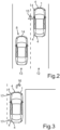
- Fig. 2 shows a traffic situation in which the motor vehicle 1 is moving in a first lane 12.
- another motor vehicle 14 is located as the object 8.
- the object 8 or the other motor vehicle 14 is located in a blind spot of the motor vehicle 1.
- the other motor vehicle 14 is detected by the control device using the sensor data from the ultrasonic sensors 4.
- the output device 10 is controlled by the control device 3 to output a warning to the driver of the motor vehicle 1.
- This warning which is illustrated here by the symbol 15, informs the driver of the motor vehicle 1 that a vehicle is in the blind spot. While this warning is being output, the non-detection mode for the ultrasonic sensors 4 of the motor vehicle 1 can be detected.
- the ultrasonic sensor device 2 further comprises a sensor 11, which is connected to the control device 3 for data transmission.
- the sensor 11 can be used, for example, to detect a current direction of travel, a steering movement and/or an actuation of a direction indicator. In principle, several individual sensors can also be used instead of the sensor 11. This data from the Sensor 11 can also be used by the control device 3 to detect the non-detection mode of at least one of the ultrasonic sensors 4. This is exemplified by Fig. 3 explained.
- Fig. 3 shows a schematic view of another traffic situation in which the motor vehicle 1 is located.
- the motor vehicle 1 is performing a turning maneuver to the right. This is illustrated schematically by the arrow 16.
- the turning maneuver or the steering movement of the motor vehicle 1 can be detected in advance with the help of the sensor 11 by activating the direction indicator. Alternatively, the steering movement can be detected as soon as it is started or carried out. In this way, the data from the sensor 11 can be used, which describe the steering movement or the steering angle.
- the ultrasonic sensors 4 whose installation position is arranged on a side opposite the steering movement, can be reconfigured. In this case, the motor vehicle 1 is to be steered to the right.
- the ultrasonic sensors 4, which are arranged on a left side of the motor vehicle 1, can be reconfigured. These ultrasonic sensors 4 are marked by the arrows 17. These ultrasonic sensors 4 are in the non-detection mode.
Landscapes
- Engineering & Computer Science (AREA)
- Radar, Positioning & Navigation (AREA)
- Remote Sensing (AREA)
- Physics & Mathematics (AREA)
- Computer Networks & Wireless Communication (AREA)
- General Physics & Mathematics (AREA)
- Acoustics & Sound (AREA)
- Measurement Of Velocity Or Position Using Acoustic Or Ultrasonic Waves (AREA)
- Traffic Control Systems (AREA)
Claims (12)
- Procédé pour faire fonctionner un arrangement de capteurs à ultrasons (2) d'un véhicule automobile (1), avec lequel, pour la détection d'un environnement (7) du véhicule automobile (1) au moyen d'un dispositif de commande (3), des données de capteur sont reçues en provenance d'une pluralité de capteurs à ultrasons (4) et, pour la configuration des capteurs à ultrasons (4), des données de configuration sont transmises aux capteurs à ultrasons (4) respectifs au moyen du dispositif de commande (3),une reconnaissance étant effectuée pour chacun des capteurs à ultrasons (4) afin de savoir si le capteur à ultrasons (4) se trouve dans un mode de détection, dans lequel les données de capteur du capteur à ultrasons (4) sont utilisées pour la détection de l'environnement (7), ou dans un mode de non-détection, dans lequel les données du capteur à ultrasons (4) restent ignorées pour la détection de l'environnement (7), les données de configuration étant transmises au capteur à ultrasons (4) respectif dans le cas où celui-ci se trouve dans le mode de non-détection, caractérisé en ce quele mode de non-détection est reconnu pendant une émission d'un avertissement à un conducteur du véhicule automobile (1), l'avertissement étant émis consécutivement à un objet (8) détecté dans l'environnement (7) à l'aide des données du capteur.
- Procédé selon la revendication 1,
caractérisé en ce que
la reconnaissance du fait que le capteur à ultrasons (4) se trouve dans le mode de détection ou dans le mode de non-détection est effectuée pendant un déplacement du véhicule automobile (1). - Procédé selon la revendication 1 ou 2,
caractérisé en ce que
l'avertissement décrit que l'objet (8) se trouve dans un angle mort du véhicule automobile (1). - Procédé selon la revendication 1 ou 2,
caractérisé en ce que
l'avertissement décrit qu'une distance entre le véhicule automobile (1) et l'objet (8) est inférieure à une distance minimale prédéterminée. - Procédé selon l'une quelconque des revendications précédentes,
le mode de non-détection étant reconnu lors d'une intervention dans un système de freinage et/ou une direction du véhicule automobile (1). - Procédé selon l'une quelconque des revendications précédentes,
caractérisé en ce que
un mouvement de direction imminent du véhicule automobile (1) est détecté et le mode de non-détection est reconnu dans le cas où le mouvement de direction imminent est détecté dans une direction opposée à une zone de détection du capteur à ultrasons (4). - Procédé selon l'une quelconque des revendications précédentes,
caractérisé en ce que
un mouvement de direction effectué du véhicule automobile (1) est détecté et le mode de non-détection est reconnu dans le cas où le mouvement de direction effectué est détecté dans une direction opposée à la zone de détection du capteur à ultrasons (4). - Procédé selon l'une quelconque des revendications précédentes,
caractérisé en ce que
une direction de mouvement actuelle du véhicule automobile (1) est détectée et le mode de non-détection est reconnu dans le cas où la direction de mouvement détectée est opposée à la zone de détection du capteur à ultrasons (4). - Procédé selon l'une quelconque des revendications précédentes,
caractérisé en ce que
le mode de non-détection est détecté dans le cas où l'objet (8) est détecté par au moins un capteur à ultrasons (4) supplémentaire de l'arrangement de capteurs à ultrasons (2). - Procédé selon l'une quelconque des revendications précédentes,
les données de configuration étant déterminées au moyen du dispositif de commande (3) en fonction d'une température actuelle et/ou d'une humidité de l'air dans un environnement (7) du véhicule automobile (1). - Arrangement de capteurs à ultrasons (2) pour un véhicule automobile (1), lequel est configuré conçu pour mettre en œuvre un procédé selon l'une des revendications précédentes.
- Véhicule automobile (1) comprenant un arrangement de capteurs à ultrasons (2) selon la revendication 11.
Applications Claiming Priority (2)
| Application Number | Priority Date | Filing Date | Title |
|---|---|---|---|
| DE102016109848.5A DE102016109848A1 (de) | 2016-05-30 | 2016-05-30 | Verfahren zum Betreiben einer Ultraschallsensorvorrichtung eines Kraftfahrzeugs mit Übertragung von Konfigurationsdaten, Ultraschallsensorvorrichtung sowie Kraftfahrzeug |
| PCT/EP2017/062341 WO2017207332A1 (fr) | 2016-05-30 | 2017-05-23 | Procédé de fonctionnement d'un dispositif de détection par ultrasons d'un véhicule automobile par transmission de données de configuration, dispositif de détection par ultrasons ainsi que véhicule automobile |
Publications (2)
| Publication Number | Publication Date |
|---|---|
| EP3465265A1 EP3465265A1 (fr) | 2019-04-10 |
| EP3465265B1 true EP3465265B1 (fr) | 2024-11-27 |
Family
ID=58873795
Family Applications (1)
| Application Number | Title | Priority Date | Filing Date |
|---|---|---|---|
| EP17726896.8A Active EP3465265B1 (fr) | 2016-05-30 | 2017-05-23 | Procédé de fonctionnement d'un dispositif de détection par ultrasons d'un véhicule automobile par transmission de données de configuration, dispositif de détection par ultrasons ainsi que véhicule automobile |
Country Status (3)
| Country | Link |
|---|---|
| EP (1) | EP3465265B1 (fr) |
| DE (1) | DE102016109848A1 (fr) |
| WO (1) | WO2017207332A1 (fr) |
Family Cites Families (6)
| Publication number | Priority date | Publication date | Assignee | Title |
|---|---|---|---|---|
| EP0016243A1 (fr) | 1979-02-15 | 1980-10-01 | Trevor P. Dr. Woodman | Peinture pour revêtement spectral sélectif sur surfaces métalliques et son utilisation |
| DE102004005960A1 (de) * | 2004-02-02 | 2005-08-18 | Valeo Schalter Und Sensoren Gmbh | Hindernisdetektionsvorrichtung und Verfahren zu deren Betrieb |
| JP4346521B2 (ja) * | 2004-07-28 | 2009-10-21 | 株式会社デンソー | 障害物検知装置 |
| DE102004038496A1 (de) * | 2004-08-07 | 2006-03-16 | Robert Bosch Gmbh | Verfahren und Vorrichtung zur Abstandsmessung eines sich in der Umgebung eines Kraftfahrzeuges befindlichen Hindernisses |
| DE102007026688A1 (de) * | 2007-06-08 | 2008-12-11 | Robert Bosch Gmbh | Verfahren zur Funktionsprüfung eines Abstandsmesssystems |
| DE102013211419A1 (de) * | 2013-06-18 | 2014-12-18 | Robert Bosch Gmbh | Ultraschallbasierter Meßsensor und Verfahren zum Betreiben eines ultraschallbasierten Meßsensors |
-
2016
- 2016-05-30 DE DE102016109848.5A patent/DE102016109848A1/de active Pending
-
2017
- 2017-05-23 EP EP17726896.8A patent/EP3465265B1/fr active Active
- 2017-05-23 WO PCT/EP2017/062341 patent/WO2017207332A1/fr not_active Ceased
Also Published As
| Publication number | Publication date |
|---|---|
| WO2017207332A1 (fr) | 2017-12-07 |
| DE102016109848A1 (de) | 2017-11-30 |
| EP3465265A1 (fr) | 2019-04-10 |
Similar Documents
| Publication | Publication Date | Title |
|---|---|---|
| EP1660362B1 (fr) | Procede et dispositif pour saisir la distance momentanee separant un vehicule d'un obstacle | |
| EP2888602B1 (fr) | Procédé de commande améliorée de capteurs à ultrasons, système d'aide à la conduite et véhicule à moteur | |
| EP2081052B1 (fr) | Dispositif de détection d'un véhicule et procédé de détection correspondant | |
| EP3230763B1 (fr) | Procédé de détection d'un objet dans une zone d'ouverture d'une porte d'un véhicule automobile, système d'aide à la conduite et véhicule automobile | |
| DE112017001351B4 (de) | Fahrassistenzvorrichtung | |
| EP2028072B1 (fr) | Véhicule automobile doté d'un système d'assistance au changement de voie ou de suivi de voie ainsi que d'un système d'aide au stationnement | |
| EP2289059B1 (fr) | Procédé pour faire fonctionner un système d'aide à la conduite lors de la réalisation d'un créneau | |
| EP2781421A2 (fr) | Suppression des perturbations dans la surveillance de l'angle mort | |
| DE102010007468B4 (de) | System und Verfahren zum Validieren von Betriebsweisen eines adaptiven Tempomats | |
| DE102018001055A1 (de) | Verfahren zur Auslösung eines selbsttätigen Notbremsvorgangs bei einer Fahrzeugkolonne | |
| DE102005009702A1 (de) | Abstandsmessvorrichtung und Verfahren zur Funktionsprüfung einer Abstandsmessung | |
| DE102008007667A1 (de) | Verfahren zum Betreiben eines Einparkhilfesystems | |
| EP2766244B1 (fr) | Procédé d'assistance à un conducteur de véhicule lors d'une man uvre de sortie depuis une place de stationnement en épi | |
| DE102015200020A1 (de) | Fahrzeugsteuervorrichtung und Fahrzeug | |
| DE102006002232B4 (de) | Anfahrwarner mit Kollisionsmelder bei Nutzfahrzeug | |
| DE102015107392A1 (de) | Verfahren zum Erfassen eines Objekts in einer Umgebung eines Kraftfahrzeugs anhand von fusionierten Sensordaten, Steuereinrichtung, Fahrerassistenzsystem sowie Kraftfahrzeug | |
| EP3602119B1 (fr) | Procédé de détection d'un objet dans une zone environnante d'un véhicule à moteur avec classification de l'objet, dispositif de capteur ultrasonique et véhicule à moteur | |
| EP2921364B1 (fr) | Dispositif, procédé et véhicule destinés à empêcher l'émission d'avertissements de collision et/ou d'avertissements de distance, en particulier pendant un remorquage | |
| EP3195009B1 (fr) | Procédé de fonctionnement d'un dispositif de détection par ultrasons d'un véhicule automobile, dispositif de détection par ultrasons, système d'aide au conducteur et véhicule automobile | |
| DE102009034963B4 (de) | Verfahren zum Betrieb eines Kraftfahrzeugs mit einem Längsführungssystem umfassend eine Fernbereichssensorik und eine Nahbereichssensorik | |
| EP3230765A1 (fr) | Procédé pour faire fonctionner un dispositif de détection pour véhicule automobile avec sélection de données de capteur, dispositif de détection et véhicule automobile | |
| EP3465265B1 (fr) | Procédé de fonctionnement d'un dispositif de détection par ultrasons d'un véhicule automobile par transmission de données de configuration, dispositif de détection par ultrasons ainsi que véhicule automobile | |
| DE102015103360B4 (de) | Notfallfahrzeugmanövrierkommunikationsmittel | |
| DE102006002662A1 (de) | Sicherheitseinrichtung für ein Fahrzeug und Verfahren zum Betrieb einer Sicherheitseinrichtung | |
| DE102019216686A1 (de) | Verfahren zum sicheren Abschleppen eines Fahrzeugs |
Legal Events
| Date | Code | Title | Description |
|---|---|---|---|
| STAA | Information on the status of an ep patent application or granted ep patent |
Free format text: STATUS: UNKNOWN |
|
| STAA | Information on the status of an ep patent application or granted ep patent |
Free format text: STATUS: THE INTERNATIONAL PUBLICATION HAS BEEN MADE |
|
| PUAI | Public reference made under article 153(3) epc to a published international application that has entered the european phase |
Free format text: ORIGINAL CODE: 0009012 |
|
| STAA | Information on the status of an ep patent application or granted ep patent |
Free format text: STATUS: REQUEST FOR EXAMINATION WAS MADE |
|
| 17P | Request for examination filed |
Effective date: 20181030 |
|
| AK | Designated contracting states |
Kind code of ref document: A1 Designated state(s): AL AT BE BG CH CY CZ DE DK EE ES FI FR GB GR HR HU IE IS IT LI LT LU LV MC MK MT NL NO PL PT RO RS SE SI SK SM TR |
|
| AX | Request for extension of the european patent |
Extension state: BA ME |
|
| DAV | Request for validation of the european patent (deleted) | ||
| DAX | Request for extension of the european patent (deleted) | ||
| STAA | Information on the status of an ep patent application or granted ep patent |
Free format text: STATUS: EXAMINATION IS IN PROGRESS |
|
| 17Q | First examination report despatched |
Effective date: 20210820 |
|
| P01 | Opt-out of the competence of the unified patent court (upc) registered |
Effective date: 20230528 |
|
| REG | Reference to a national code |
Ref country code: DE Ref legal event code: R079 Free format text: PREVIOUS MAIN CLASS: G01S0015930000 Ipc: G01S0007000000 Ref country code: DE Ref legal event code: R079 Ref document number: 502017016576 Country of ref document: DE Free format text: PREVIOUS MAIN CLASS: G01S0015930000 Ipc: G01S0007000000 |
|
| GRAP | Despatch of communication of intention to grant a patent |
Free format text: ORIGINAL CODE: EPIDOSNIGR1 |
|
| STAA | Information on the status of an ep patent application or granted ep patent |
Free format text: STATUS: GRANT OF PATENT IS INTENDED |
|
| RIC1 | Information provided on ipc code assigned before grant |
Ipc: G01S 15/931 20200101ALI20240619BHEP Ipc: G01S 7/52 20060101ALI20240619BHEP Ipc: G01S 7/00 20060101AFI20240619BHEP |
|
| INTG | Intention to grant announced |
Effective date: 20240710 |
|
| GRAS | Grant fee paid |
Free format text: ORIGINAL CODE: EPIDOSNIGR3 |
|
| GRAA | (expected) grant |
Free format text: ORIGINAL CODE: 0009210 |
|
| STAA | Information on the status of an ep patent application or granted ep patent |
Free format text: STATUS: THE PATENT HAS BEEN GRANTED |
|
| AK | Designated contracting states |
Kind code of ref document: B1 Designated state(s): AL AT BE BG CH CY CZ DE DK EE ES FI FR GB GR HR HU IE IS IT LI LT LU LV MC MK MT NL NO PL PT RO RS SE SI SK SM TR |
|
| REG | Reference to a national code |
Ref country code: GB Ref legal event code: FG4D Free format text: NOT ENGLISH |
|
| REG | Reference to a national code |
Ref country code: CH Ref legal event code: EP |
|
| REG | Reference to a national code |
Ref country code: IE Ref legal event code: FG4D Free format text: LANGUAGE OF EP DOCUMENT: GERMAN |
|
| REG | Reference to a national code |
Ref country code: DE Ref legal event code: R096 Ref document number: 502017016576 Country of ref document: DE |
|
| REG | Reference to a national code |
Ref country code: LT Ref legal event code: MG9D |
|
| REG | Reference to a national code |
Ref country code: NL Ref legal event code: MP Effective date: 20241127 |
|
| PG25 | Lapsed in a contracting state [announced via postgrant information from national office to epo] |
Ref country code: PT Free format text: LAPSE BECAUSE OF FAILURE TO SUBMIT A TRANSLATION OF THE DESCRIPTION OR TO PAY THE FEE WITHIN THE PRESCRIBED TIME-LIMIT Effective date: 20250327 Ref country code: HR Free format text: LAPSE BECAUSE OF FAILURE TO SUBMIT A TRANSLATION OF THE DESCRIPTION OR TO PAY THE FEE WITHIN THE PRESCRIBED TIME-LIMIT Effective date: 20241127 Ref country code: IS Free format text: LAPSE BECAUSE OF FAILURE TO SUBMIT A TRANSLATION OF THE DESCRIPTION OR TO PAY THE FEE WITHIN THE PRESCRIBED TIME-LIMIT Effective date: 20250327 |
|
| PG25 | Lapsed in a contracting state [announced via postgrant information from national office to epo] |
Ref country code: FI Free format text: LAPSE BECAUSE OF FAILURE TO SUBMIT A TRANSLATION OF THE DESCRIPTION OR TO PAY THE FEE WITHIN THE PRESCRIBED TIME-LIMIT Effective date: 20241127 Ref country code: NL Free format text: LAPSE BECAUSE OF FAILURE TO SUBMIT A TRANSLATION OF THE DESCRIPTION OR TO PAY THE FEE WITHIN THE PRESCRIBED TIME-LIMIT Effective date: 20241127 |
|
| PG25 | Lapsed in a contracting state [announced via postgrant information from national office to epo] |
Ref country code: BG Free format text: LAPSE BECAUSE OF FAILURE TO SUBMIT A TRANSLATION OF THE DESCRIPTION OR TO PAY THE FEE WITHIN THE PRESCRIBED TIME-LIMIT Effective date: 20241127 |
|
| PG25 | Lapsed in a contracting state [announced via postgrant information from national office to epo] |
Ref country code: ES Free format text: LAPSE BECAUSE OF FAILURE TO SUBMIT A TRANSLATION OF THE DESCRIPTION OR TO PAY THE FEE WITHIN THE PRESCRIBED TIME-LIMIT Effective date: 20241127 |
|
| PG25 | Lapsed in a contracting state [announced via postgrant information from national office to epo] |
Ref country code: NO Free format text: LAPSE BECAUSE OF FAILURE TO SUBMIT A TRANSLATION OF THE DESCRIPTION OR TO PAY THE FEE WITHIN THE PRESCRIBED TIME-LIMIT Effective date: 20250227 |
|
| PG25 | Lapsed in a contracting state [announced via postgrant information from national office to epo] |
Ref country code: LV Free format text: LAPSE BECAUSE OF FAILURE TO SUBMIT A TRANSLATION OF THE DESCRIPTION OR TO PAY THE FEE WITHIN THE PRESCRIBED TIME-LIMIT Effective date: 20241127 Ref country code: GR Free format text: LAPSE BECAUSE OF FAILURE TO SUBMIT A TRANSLATION OF THE DESCRIPTION OR TO PAY THE FEE WITHIN THE PRESCRIBED TIME-LIMIT Effective date: 20250228 |
|
| PG25 | Lapsed in a contracting state [announced via postgrant information from national office to epo] |
Ref country code: PL Free format text: LAPSE BECAUSE OF FAILURE TO SUBMIT A TRANSLATION OF THE DESCRIPTION OR TO PAY THE FEE WITHIN THE PRESCRIBED TIME-LIMIT Effective date: 20241127 |
|
| PG25 | Lapsed in a contracting state [announced via postgrant information from national office to epo] |
Ref country code: RS Free format text: LAPSE BECAUSE OF FAILURE TO SUBMIT A TRANSLATION OF THE DESCRIPTION OR TO PAY THE FEE WITHIN THE PRESCRIBED TIME-LIMIT Effective date: 20250227 |
|
| PG25 | Lapsed in a contracting state [announced via postgrant information from national office to epo] |
Ref country code: SM Free format text: LAPSE BECAUSE OF FAILURE TO SUBMIT A TRANSLATION OF THE DESCRIPTION OR TO PAY THE FEE WITHIN THE PRESCRIBED TIME-LIMIT Effective date: 20241127 |
|
| PGFP | Annual fee paid to national office [announced via postgrant information from national office to epo] |
Ref country code: DE Payment date: 20250513 Year of fee payment: 9 |
|
| PG25 | Lapsed in a contracting state [announced via postgrant information from national office to epo] |
Ref country code: DK Free format text: LAPSE BECAUSE OF FAILURE TO SUBMIT A TRANSLATION OF THE DESCRIPTION OR TO PAY THE FEE WITHIN THE PRESCRIBED TIME-LIMIT Effective date: 20241127 |
|
| PGFP | Annual fee paid to national office [announced via postgrant information from national office to epo] |
Ref country code: GB Payment date: 20250521 Year of fee payment: 9 |
|
| PG25 | Lapsed in a contracting state [announced via postgrant information from national office to epo] |
Ref country code: EE Free format text: LAPSE BECAUSE OF FAILURE TO SUBMIT A TRANSLATION OF THE DESCRIPTION OR TO PAY THE FEE WITHIN THE PRESCRIBED TIME-LIMIT Effective date: 20241127 |
|
| PGFP | Annual fee paid to national office [announced via postgrant information from national office to epo] |
Ref country code: FR Payment date: 20250530 Year of fee payment: 9 |
|
| PG25 | Lapsed in a contracting state [announced via postgrant information from national office to epo] |
Ref country code: RO Free format text: LAPSE BECAUSE OF FAILURE TO SUBMIT A TRANSLATION OF THE DESCRIPTION OR TO PAY THE FEE WITHIN THE PRESCRIBED TIME-LIMIT Effective date: 20241127 |
|
| PG25 | Lapsed in a contracting state [announced via postgrant information from national office to epo] |
Ref country code: SK Free format text: LAPSE BECAUSE OF FAILURE TO SUBMIT A TRANSLATION OF THE DESCRIPTION OR TO PAY THE FEE WITHIN THE PRESCRIBED TIME-LIMIT Effective date: 20241127 |
|
| PG25 | Lapsed in a contracting state [announced via postgrant information from national office to epo] |
Ref country code: CZ Free format text: LAPSE BECAUSE OF FAILURE TO SUBMIT A TRANSLATION OF THE DESCRIPTION OR TO PAY THE FEE WITHIN THE PRESCRIBED TIME-LIMIT Effective date: 20241127 |
|
| PG25 | Lapsed in a contracting state [announced via postgrant information from national office to epo] |
Ref country code: IT Free format text: LAPSE BECAUSE OF FAILURE TO SUBMIT A TRANSLATION OF THE DESCRIPTION OR TO PAY THE FEE WITHIN THE PRESCRIBED TIME-LIMIT Effective date: 20241127 |
|
| REG | Reference to a national code |
Ref country code: DE Ref legal event code: R097 Ref document number: 502017016576 Country of ref document: DE |
|
| PG25 | Lapsed in a contracting state [announced via postgrant information from national office to epo] |
Ref country code: SE Free format text: LAPSE BECAUSE OF FAILURE TO SUBMIT A TRANSLATION OF THE DESCRIPTION OR TO PAY THE FEE WITHIN THE PRESCRIBED TIME-LIMIT Effective date: 20241127 |
|
| PLBE | No opposition filed within time limit |
Free format text: ORIGINAL CODE: 0009261 |
|
| STAA | Information on the status of an ep patent application or granted ep patent |
Free format text: STATUS: NO OPPOSITION FILED WITHIN TIME LIMIT |
|
| REG | Reference to a national code |
Ref country code: CH Ref legal event code: L10 Free format text: ST27 STATUS EVENT CODE: U-0-0-L10-L00 (AS PROVIDED BY THE NATIONAL OFFICE) Effective date: 20251008 |
|
| 26N | No opposition filed |
Effective date: 20250828 |
|
| REG | Reference to a national code |
Ref country code: CH Ref legal event code: H13 Free format text: ST27 STATUS EVENT CODE: U-0-0-H10-H13 (AS PROVIDED BY THE NATIONAL OFFICE) Effective date: 20251223 |
|
| PG25 | Lapsed in a contracting state [announced via postgrant information from national office to epo] |
Ref country code: LU Free format text: LAPSE BECAUSE OF NON-PAYMENT OF DUE FEES Effective date: 20250523 |
|
| PG25 | Lapsed in a contracting state [announced via postgrant information from national office to epo] |
Ref country code: CH Free format text: LAPSE BECAUSE OF NON-PAYMENT OF DUE FEES Effective date: 20250531 |
|
| REG | Reference to a national code |
Ref country code: BE Ref legal event code: MM Effective date: 20250531 |
|
| PG25 | Lapsed in a contracting state [announced via postgrant information from national office to epo] |
Ref country code: MC Free format text: LAPSE BECAUSE OF FAILURE TO SUBMIT A TRANSLATION OF THE DESCRIPTION OR TO PAY THE FEE WITHIN THE PRESCRIBED TIME-LIMIT Effective date: 20241127 |
|
| PG25 | Lapsed in a contracting state [announced via postgrant information from national office to epo] |
Ref country code: IE Free format text: LAPSE BECAUSE OF NON-PAYMENT OF DUE FEES Effective date: 20250523 |
|
| PG25 | Lapsed in a contracting state [announced via postgrant information from national office to epo] |
Ref country code: BE Free format text: LAPSE BECAUSE OF NON-PAYMENT OF DUE FEES Effective date: 20250531 |