EP1660372B1 - Systeme de conservation du vin utilisant un systeme central de mise sous vide - Google Patents
Systeme de conservation du vin utilisant un systeme central de mise sous vide Download PDFInfo
- Publication number
- EP1660372B1 EP1660372B1 EP04781749A EP04781749A EP1660372B1 EP 1660372 B1 EP1660372 B1 EP 1660372B1 EP 04781749 A EP04781749 A EP 04781749A EP 04781749 A EP04781749 A EP 04781749A EP 1660372 B1 EP1660372 B1 EP 1660372B1
- Authority
- EP
- European Patent Office
- Prior art keywords
- vacuum
- bottle
- tank
- valve
- stopper
- Prior art date
- Legal status (The legal status is an assumption and is not a legal conclusion. Google has not performed a legal analysis and makes no representation as to the accuracy of the status listed.)
- Expired - Lifetime
Links
- 238000004321 preservation Methods 0.000 title claims abstract description 13
- 235000014101 wine Nutrition 0.000 title description 55
- 235000013361 beverage Nutrition 0.000 claims abstract description 6
- 238000000034 method Methods 0.000 claims description 12
- 230000008713 feedback mechanism Effects 0.000 claims description 6
- 238000004891 communication Methods 0.000 claims description 4
- 239000007788 liquid Substances 0.000 claims description 4
- 239000000356 contaminant Substances 0.000 claims description 2
- 239000012530 fluid Substances 0.000 claims description 2
- 238000006073 displacement reaction Methods 0.000 claims 2
- 235000014676 Phragmites communis Nutrition 0.000 description 7
- 239000011261 inert gas Substances 0.000 description 7
- 241001639412 Verres Species 0.000 description 6
- 239000011521 glass Substances 0.000 description 6
- XKRFYHLGVUSROY-UHFFFAOYSA-N Argon Chemical compound [Ar] XKRFYHLGVUSROY-UHFFFAOYSA-N 0.000 description 4
- 230000008901 benefit Effects 0.000 description 3
- IJGRMHOSHXDMSA-UHFFFAOYSA-N Atomic nitrogen Chemical compound N#N IJGRMHOSHXDMSA-UHFFFAOYSA-N 0.000 description 2
- 229910052786 argon Inorganic materials 0.000 description 2
- QVGXLLKOCUKJST-UHFFFAOYSA-N atomic oxygen Chemical compound [O] QVGXLLKOCUKJST-UHFFFAOYSA-N 0.000 description 2
- 235000013405 beer Nutrition 0.000 description 2
- 239000007799 cork Substances 0.000 description 2
- 239000001301 oxygen Substances 0.000 description 2
- 229910052760 oxygen Inorganic materials 0.000 description 2
- 238000005057 refrigeration Methods 0.000 description 2
- 241001411320 Eriogonum inflatum Species 0.000 description 1
- 244000089486 Phragmites australis subsp australis Species 0.000 description 1
- 230000032683 aging Effects 0.000 description 1
- 230000005587 bubbling Effects 0.000 description 1
- 230000015556 catabolic process Effects 0.000 description 1
- 238000006731 degradation reaction Methods 0.000 description 1
- 230000003111 delayed effect Effects 0.000 description 1
- 230000002939 deleterious effect Effects 0.000 description 1
- 238000010586 diagram Methods 0.000 description 1
- 230000000694 effects Effects 0.000 description 1
- 239000000796 flavoring agent Substances 0.000 description 1
- 235000019634 flavors Nutrition 0.000 description 1
- 239000007789 gas Substances 0.000 description 1
- 239000000203 mixture Substances 0.000 description 1
- 229910052757 nitrogen Inorganic materials 0.000 description 1
- 230000003647 oxidation Effects 0.000 description 1
- 238000007254 oxidation reaction Methods 0.000 description 1
- 239000003755 preservative agent Substances 0.000 description 1
- 230000002335 preservative effect Effects 0.000 description 1
- 238000005086 pumping Methods 0.000 description 1
- 238000007789 sealing Methods 0.000 description 1
- 229920002994 synthetic fiber Polymers 0.000 description 1
- 235000021419 vinegar Nutrition 0.000 description 1
- 239000000052 vinegar Substances 0.000 description 1
- 239000002699 waste material Substances 0.000 description 1
Images


Classifications
-
- B—PERFORMING OPERATIONS; TRANSPORTING
- B65—CONVEYING; PACKING; STORING; HANDLING THIN OR FILAMENTARY MATERIAL
- B65B—MACHINES, APPARATUS OR DEVICES FOR, OR METHODS OF, PACKAGING ARTICLES OR MATERIALS; UNPACKING
- B65B31/00—Packaging articles or materials under special atmospheric or gaseous conditions; Adding propellants to aerosol containers
- B65B31/02—Filling, closing, or filling and closing, containers or wrappers in chambers maintained under vacuum or superatmospheric pressure or containing a special atmosphere, e.g. of inert gas
- B65B31/025—Filling, closing, or filling and closing, containers or wrappers in chambers maintained under vacuum or superatmospheric pressure or containing a special atmosphere, e.g. of inert gas specially adapted for rigid or semi-rigid containers
- B65B31/027—Filling, closing, or filling and closing, containers or wrappers in chambers maintained under vacuum or superatmospheric pressure or containing a special atmosphere, e.g. of inert gas specially adapted for rigid or semi-rigid containers closed by a stopper
-
- C—CHEMISTRY; METALLURGY
- C12—BIOCHEMISTRY; BEER; SPIRITS; WINE; VINEGAR; MICROBIOLOGY; ENZYMOLOGY; MUTATION OR GENETIC ENGINEERING
- C12H—PASTEURISATION, STERILISATION, PRESERVATION, PURIFICATION, CLARIFICATION OR AGEING OF ALCOHOLIC BEVERAGES; METHODS FOR ALTERING THE ALCOHOL CONTENT OF FERMENTED SOLUTIONS OR ALCOHOLIC BEVERAGES
- C12H1/00—Pasteurisation, sterilisation, preservation, purification, clarification, or ageing of alcoholic beverages
- C12H1/12—Pasteurisation, sterilisation, preservation, purification, clarification, or ageing of alcoholic beverages without precipitation
Definitions
- the present invention is directed to an apparatus for preserving still beverages. More particularly the present invention is directed to an apparatus for the preservation of wine through the removal of air from a previously opened bottle.
- One known method for the preservation of wine in a bottle is to evacuate the air space above the liquid once some of the wine has been consumed and then seal the bottle with a stopper.
- One system for accomplishing this is the Vac-U-Vin TM system.
- the Vac-U-Vin TM system requires a special stopper to be placed in the bottle neck.
- This stopper has a slit that acts as a non-return valve. The valve opens if a vacuum is created above the stopper to allow air to be sucked out of the bottle but closes again as soon as the external pressure is greater than the pressure inside the bottle.
- a manual suction pump is used to create a vacuum above the stopper.
- a further system for evacuating the air space above the liquid is known from JP-A-2001 354 206 .
- U.S. Patent. No. 4,684,033 describes another known method of preserving wine in an opened wine bottle by inflating a bladder inside the bottle to fill the space above the liquid and to prevent oxygen from reaching the wine. To do this is a time-consuming operation, which requires considerable manual dexterity in introducing a deflated bladder into the bottle and then inflating it. This method also requires that the bladder be removed, washed, and cleaned after each use.
- Another option for preserving an opened bottle of wine involves pouring the contents of the opened bottled into a smaller bottle, decanter or the like having less airspace above the wine, inserting an airtight stopper and then storing. Finally, the air in an opened bottle may be replaced with a layer of inert gas, such as nitrogen, and stored.
- a stopper is inserted into a bottle to replace the cork and remain with the bottle for the lifetime of the wine.
- the stopper is provided with passageways and valves to permit the bottle to be pressed against a contact-operated dispenser head, directing a blast of inert gas such as Argon into the bottle to expel at first air, and subsequently a mixture of air and Argon or other inert gas, until the percentage of oxygen is so low as not to represent a threat to the wine.
- inert gas such as Argon
- the Verre de Vin system can be used to evacuate air from a bottle of wine, it has some inherent operational-as well as commercial-drawbacks. Initially, because the system is designed without a vacuum tank, the pump must cycle on and off with each depression of the housing. This creates at least three interrelated problems. Initially, the pump is noisy and can be annoying to patrons of the establishment in which such a device is installed. Secondly, the pump can only be started and stopped a predetermined number of times over a set period. Any more frequent actuation can result in the failure of the motor. According to the specifications, the Verre de Vin system can evacuate no more than fifteen bottles over a five-minute period.
- One embodiment of the present invention is directed to an apparatus for the preservation of still beverages.
- the apparatus includes a vacuum tank capable of maintaining a standing vacuum.
- the apparatus also includes a vacuum pump connected to the vacuum tank.
- the vacuum pump reduces the pressure in the vacuum tank to create the vacuum.
- the apparatus further includes a vacuum line fluidly connected to the vacuum tank.
- At least one valve head is connected to the vacuum line and interfaces with a bottle having a stopper placed therein.
- the valve head also includes an actuator, whereupon actuation, air in the bottle is evacuated by exposure to the vacuum and is prevented from reentering the bottle by the stopper.
- a further embodiment of the present invention is directed to a method of preserving still beverages.
- the method includes inserting a stopper having a one-way valve into a bottle and inserting the stoppered bottle into the valve head of an apparatus to substantially evacuate air from the bottle.
- the apparatus has a vacuum tank for maintaining a standing vacuum, a vacuum pump connected to the vacuum tank for reducing pressure in the tank to create the vacuum, a vacuum line connected to the vacuum tank, and a valve head connected to the vacuum line. Actuating the valve head permits the application of the vacuum in the vacuum line to the bottle to substantially evacuate air contained therein.
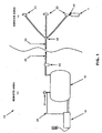
- Fig. 1 depicts a wine preservation system 10 according to one embodiment of the present invention.
- the wine preservative system 10 may be divided between a remote/central area 12 and a service area 14.
- the remote/central area 12 includes a vacuum pump 16 which may be electrically powered.
- the pump 16 takes suction on the vacuum tank 18 drawing any air from the vacuum tank 18 until a desired standing vacuum level is achieved.
- the vacuum level is preferably registered by a vacuum gauge 24.
- the vacuum gauge 24 and/or the vacuum tank 18 is/are connected to the pump 16 via a pump feedback mechanism 26.
- the feedback mechanism 26 stops the pump upon reaching the desired vacuum level in the vacuum tank 18.
- the feedback mechanism may be an adjustable electrical, pneumatic, hydraulic, or the like type of feedback element for starting and stopping the pump according to the vacuum level in the vacuum tank 18. It has been determined that at vacuum levels above 25 in-Hg, gases entrained in the wine tend to be released, causing bubbling of normally still wine. This effect is generally not desirable and may in fact have deleterious effects on wine. Accordingly it is preferable that the vacuum level in the system 10 does not exceed 0.847 bar (25 in-Hg). In a preferred embodiment, a standing vacuum is maintained between about 0.576 bar - 0.847 bar (17-25 in-Hg), most preferably between about 0.745 bar - 0.813 bar (22-24 in-Hg). It has been observed that a bottle of wine vacuum-sealed to 0.745 bar - 0.813 bar (22-24 in-Hg) can last up to two weeks without any noticeable degradation due to oxidation.
- the vacuum tank 18 is connected to a vacuum line 20 that traverses the remote/central and service areas.
- the vacuum line 20 may be divided by a manifold 30 to service a plurality of valve heads 22 in one or more service areas 14.
- the manifold 30 is shown in a service area 14, however, its location may be in either a service area 14 or the remote/central area 12 as desired by the user.
- the remote/central area may be in the basement of an establishment, storeroom, or some other suitable location that is remote from where patrons are likely to congregate. Remote locations of this sort are commonly used in restaurants and bars for beer kegs.
- the kegs are stored remotely and connected by hoses to taps at the bar for dispensing of the beer contained therein.
- the tank 18 and the pump 16 components of the present wine preservation system may advantageously be located remotely.
- a trap or filter 32 may be placed anywhere in-line between the tank and valve heads.
- additional vacuum lines 30 and valve heads 22 may be added by direct connection to the tank, manifold, or vacuum line. As more lines are added, the overall efficiency of the system is increased due to the increase in volume.
- valve heads 22 makes the wine preservation system of the present invention a multi-user system.
- One remote/central vacuum tank 18 and pump 16 can support multiple valve heads 22 located at multiple service areas 14. Because of the minimal space requirements of valve head 22 and its vacuum line 30 relative to the pump 16 and vacuum tank 18, the present system does not take up valuable space in a service area 14.
- a valve head 22 is shown in Fig. 2 comprised of a handle 60, a valve body 62, an actuator 64, and a bottle interface 66.
- the handle 60 serves two functions. Initially, the handle 60 provides a convenient means for the user to grasp the valve head 22; secondly, it transmits the vacuum from the vacuum line 20 to the valve body 62.
- the bottle interface 66 seals releasably with a stopper 45, which may be inserted into a wine bottle or other vessel as shown in Fig. 2
- the bottle interface 66 is formed having a substantially frustum shape (truncated cone).
- the base, or larger diameter section, has a recess 80 for accepting a wine bottle as shown in Fig. 3 .
- the smaller diameter truncated portion of the cone shape may be directly connected to the valve body 62, or connected to the valve body 62 via a tube 82 as shown in Figs. 2 and 4 .
- the recess 80 of the bottle interface 66 receives a one-way stopper 45 and forms a substantially airtight seal between the stopper 45 and the bottle interface 66.
- the valve body 62 includes a valve stem 72 shown in Fig. 4 .
- the valve stem 72 is preferably spring-biased to the normally closed position. This ensures that upon release of the actuator 64 by the user, the valve stem 72 and an associated valve seat 76 will return to a closed position, thereby maintaining the system vacuum.
- Other valves may also be used without departing from the scope of the present invention.
- the valve body 62 has a vacuum relief port 70.
- the vacuum relief port 70 allows for equalization in pressure between the atmosphere and an area above the stopper 45 in the bottle interface 66. Without such equalization of pressure, it may be difficult to remove the bottle interface 66 from the stopper 45 and the bottle 1, following the application of a vacuum to the valve head 22, as the bottle 1 and stopper 45 may be suctioned to the valve head 22.
- the valve body 62 includes a valve stem 72 having a reduced diameter portion 74 and a valve seat 76.
- the reduced diameter portion 74 permits airflow between the vacuum relief port 70 through the valve body 62 and into the bottle interface 66. This enables the equalization of pressure between the atmosphere and an area above the stopper 45 when placed in the bottle interface 66.
- the valve seat 76 prevents flow between the system vacuum and the atmosphere or the remainder of the valve body.
- valve seat 76 connected to the valve stem 72 is displaced axially.
- the reduced diameter portion 74 is projected through an opening created by the movement of the valve seat 76.
- the valve seat 76 has a larger diameter than the reduced diameter portion 74 of the valve stem 72. This difference in diameter provides a flow path for the air to be evacuated from the bottle 1. Because the bottle interface 66 and the stopper 45 are exposed to and in fluid communication with the vacuum of the system 10, air in the bottle 1 is drawn through the stopper 45, through the bottle interface 66, through the valve body 62 and into the vacuum line 30. Because the vacuum relief port 70 is covered during vacuum operation there is no communication between the vacuum of the system and the atmosphere.
- the valve head 22 is adapted to interface with a one-way bottle stopper, such as that commercially available and used in the Vac-U-Vin TM system.
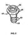
- Fig. 5 depicts one such stopper 45.
- the stopper 45 seals releasably with the bottle interface 66 of the valve head 22.
- the stopper 45 is comprised of a reed valve 54, a vacuum seal 52, a flange 46, a neck portion 48 and bottle seal rings 50.
- the reed valve 54 prevents the flow of air from the atmosphere from entering the bottle.
- the differential in pressure between the atmosphere and the interior of the bottle when under a vacuum, force the reeds of the reed valve 54 to compress against each other and form a seal.
- the stopper 45 Upon application of a vacuum to the bottle interface 66 of the valve head 22, and thereby to the stopper 45, air will be drawn out of the bottle 1 through the reed valve 54.
- the flange 46 ensures that the stopper 45 is not forced into the bottle or drawn into the bottle by the vacuum created therein.
- the neck portion 48 of the stopper 45 is inserted into the bottle and stabilizes the connection of the stopper 45 in the bottle as well as forms a seal around the opening in the bottle.
- the bottle seal rings 50 assist in ensuring that there is an airtight seal between the bottle and the stopper 45.
- a releasable seal is formed between the bottle interface 66 of the valve head 22 and the vacuum seal 52 of the stopper 45.
- Subsequent actuation of the actuator 64 subjects the area of the bottle interface 66 above the stopper 45 to a vacuum.
- the creation of the vacuum above the reed valves 54 creates a pressure differential between the vacuum in the bottle interface 66 and the pressure in the bottle 1. This pressure differential causes air in the bottle 1 to flow out through the reed valves until the pressure in the bottle 1 equalizes with the vacuum level in the system. Because of the large differential in relative volumes between the bottle 1 and the system 10, the contents of the bottle can be rapidly placed under a vacuum to preserve its contents.
- a system as described above having a 95 liter vacuum tank can impart a vacuum of 22 in-Hg and thereby substantially evacuate the air in a standard 750 ml bottle of wine that is three-quarters full ( i.e., following the dispensing of approximately one glass) in approximately 1.5 seconds.
- a 750 ml bottle that is approximately one-half full the air can be substantially evacuated in approximately 2.5 seconds, and in a bottle that is one-quarter full ( i.e., having approximately one glass of wine remaining), the air can be substantially evacuated in approximately 3.5 seconds. Because of the speed and ease of use of the present system, it is far more likely to be used in a busy setting than other wine preservation systems and methods.
- a preferred range for the standing vacuum is between about 0.576 bar - 0.847 bar (17-25 in-Hg), most preferably between about 0.745 bar - 0.813 bar (22-24 in-Hg).
- the wine preservation system of the present invention overcomes the problems associated with the prior art though the use of a single, centrally-located vacuum system supporting one or more valve heads for use in the wine serving area(s).
- the present invention allows for multiple users at the same time. Rapid, consistent vacuum pressure is applied to every bottle, every time.
- the system provides essentially noise-free operation at the valve head and is quieter and simpler to use than commercially available mechanical pump systems located at the bar/service area. Further, the system is cheaper to operate, faster and less intrusive than such mechanical pump systems or preservation systems using inert gases.
Landscapes
- Chemical & Material Sciences (AREA)
- Engineering & Computer Science (AREA)
- Organic Chemistry (AREA)
- Life Sciences & Earth Sciences (AREA)
- Zoology (AREA)
- Health & Medical Sciences (AREA)
- Mechanical Engineering (AREA)
- Biochemistry (AREA)
- Bioinformatics & Cheminformatics (AREA)
- General Engineering & Computer Science (AREA)
- General Health & Medical Sciences (AREA)
- Genetics & Genomics (AREA)
- Dispersion Chemistry (AREA)
- Wood Science & Technology (AREA)
- Food Science & Technology (AREA)
- Devices For Dispensing Beverages (AREA)
- Food Preservation Except Freezing, Refrigeration, And Drying (AREA)
- Distillation Of Fermentation Liquor, Processing Of Alcohols, Vinegar And Beer (AREA)
- Agricultural Chemicals And Associated Chemicals (AREA)
- Medicines Containing Material From Animals Or Micro-Organisms (AREA)
- Alcoholic Beverages (AREA)
- Vacuum Packaging (AREA)
- Closures For Containers (AREA)
- Devices For Warming Or Keeping Food Or Tableware Hot (AREA)
Claims (18)
- Appareil (10) pour la conservation de boissons non gazeuses, comprenant :un réservoir de vide (18) ;une pompe à vide (16) ;une ligne de vide (20) reliée de manière fluide audit réservoir de vide ;au moins une tête de soupape (22) reliée de manière fluide à ladite ligne de vide pour une interface avec une bouteille (1) comprenant un bouchon (45) placé sur celle-ci ;un actionneur (64), dans lequel au moment de l'actionnement l'air dans la bouteille est sensiblement évacué par exposition au vide et est empêché de retourner à l'intérieur de la bouteille par le bouchon ; etun dégagement de vide, dans lequel le dégagement de vide permet l'égalisation de la pression entre l'atmosphère et la zone au-dessus du bouchon dans la tête de soupape ;caractérisé en ce que le réservoir de vide (18) maintient un vide permanent pendant l'utilisation ;et en ce que la pompe à vide (16) est reliée de manière fluide au réservoir de vide pour réduire la pression dans ledit réservoir pour créer le vide pendant l'utilisation.
- Appareil selon la revendication 1, dans lequel ladite tête de soupape (22) comprend ledit actionneur (64).
- Appareil selon la revendication 1 ou la revendication 2, dans lequel ledit actionneur (64) déplace un siège de soupape (76) situé dans ladite tête de soupape (22) pour exposer le bouchon au vide lors du déplacement dudit siège de soupape (76).
- Appareil selon l'une quelconque des revendications précédentes, comprenant également un piège (32) dans ladite ligne de vide (20) pour empêcher le liquide ou les contaminants d'entrer dans ledit réservoir de vide (18).
- Appareil selon l'une quelconque des revendications précédentes, comprenant également un mécanisme de rétroaction (26), dans lequel ledit mécanisme de rétroaction démarre ladite pompe à vide (16) quand le vide dans ledit réservoir de vide (18) est en dessous d'un premier niveau prédéterminé et éteint ladite pompe à vide (16) quand le vide dans ledit réservoir de vide (18) atteint un second niveau prédéterminé.
- Appareil selon la revendication 1, comprenant également une jauge (24) pour déterminer le niveau du vide dans ledit réservoir de vide (18).
- Appareil selon l'une quelconque des revendications précédentes, comprenant également un collecteur (30) pour la fixation d'une pluralité de lignes de vide.
- Appareil selon la revendication 1, dans lequel la tête de soupape comprend également :un corps de soupape (62) contenant une tige de soupape (72) pour contrôler la communication du vide de ladite ligne de vide à la bouteille.
- Appareil selon la revendication 8, comprenant également un siège de soupape (76), dans lequel ledit siège de soupape (76) est disposé sur ladite tige de soupape (72) et est déplacé axialement à l'actionnement dudit actionneur (64).
- Appareil selon la revendication 9, dans lequel ladite tige de soupape (72) comprend également une partie de diamètre réduit (74) ayant un diamètre inférieur au diamètre dudit siège de soupape (76), ladite partie de diamètre réduit étant avancée à travers une ouverture créée par le déplacement axial dudit siège de soupape (76) à l'actionnement, et dans lequel l'avancement de ladite partie de diamètre réduit dans l'ouverture permet la communication fluide entre ledit corps de soupape (62) et ladite ligne de vide (20).
- Appareil selon la revendication 1, dans lequel ledit réservoir de vide maintient un vide permanent entre environ 0,576 bar (17 in-Hg) et environ 0,847 bar (25 in-Hg).
- Appareil selon la revendication 11, dans lequel ledit réservoir de vide maintient un vide permanent entre environ 0,745 bar (22 in-Hg) et environ 0,813 bar (24 in-Hg).
- Appareil selon la revendication 1, dans lequel l'air restant dans une bouteille de 750 ml partiellement consommée est sensiblement évacué dans un délai maximal d'environ 3,5 secondes.
- Appareil selon la revendication 1, dans lequel ledit dégagement de vide est un orifice de décompression (70).
- Procédé pour conserver des boissons non gazeuses en évacuant sensiblement l'air contenu dans une bouteille comprenant les étapes suivantes :insertion d'un bouchon comprenant un clapet antiretour dans une bouteille ;insertion de la bouteille bouchée dans une tête de soupape d'un appareil comportant un réservoir de vide pour maintenir un vide permanent, une pompe à vide raccordée au réservoir de vide pour réduire la pression dans le réservoir pour créer le vide, une ligne de vide raccordée au réservoir de vide, et une tête de soupape raccordée à la ligne de vide ;actionnement de la tête de soupape pour permettre l'application du vide dans la ligne de vide à la bouteille bouchée ;évacuation de l'air de la bouteille à travers le bouchon; etdégager le vide entre le bouchon et la tête de soupape une fois que le vide désiré a été atteint dans la bouteille.
- Procédé selon la revendication 15, dans lequel ledit réservoir de vide maintient un vide permanent entre environ 0,576 bar (17 in-Hg) et environ 0,847 bar (25 in-Hg).
- Procédé selon la revendication 16, dans lequel ledit réservoir de vide maintient un vide permanent entre environ 0,745 bar (22 in-Hg) et environ 0,813 bar (24 in-Hg).
- Procédé selon la revendication 15, dans lequel l'air restant dans une bouteille de 750 ml partiellement consommée est sensiblement évacué dans un délai maximal d'environ 3,5 secondes.
Applications Claiming Priority (2)
| Application Number | Priority Date | Filing Date | Title |
|---|---|---|---|
| US10/645,149 US6886605B2 (en) | 2003-08-21 | 2003-08-21 | Wine preservation system using a central vacuum |
| PCT/US2004/027129 WO2005020706A2 (fr) | 2003-08-21 | 2004-08-20 | Systeme de conservation du vin utilisant un systeme central de mise sous vide |
Publications (3)
| Publication Number | Publication Date |
|---|---|
| EP1660372A2 EP1660372A2 (fr) | 2006-05-31 |
| EP1660372A4 EP1660372A4 (fr) | 2008-02-13 |
| EP1660372B1 true EP1660372B1 (fr) | 2009-11-25 |
Family
ID=34273281
Family Applications (1)
| Application Number | Title | Priority Date | Filing Date |
|---|---|---|---|
| EP04781749A Expired - Lifetime EP1660372B1 (fr) | 2003-08-21 | 2004-08-20 | Systeme de conservation du vin utilisant un systeme central de mise sous vide |
Country Status (10)
| Country | Link |
|---|---|
| US (3) | US6886605B2 (fr) |
| EP (1) | EP1660372B1 (fr) |
| JP (1) | JP2007507396A (fr) |
| AT (1) | ATE449731T1 (fr) |
| AU (1) | AU2004268573B2 (fr) |
| BR (1) | BRPI0413760A (fr) |
| CA (1) | CA2535820C (fr) |
| DE (1) | DE602004024316D1 (fr) |
| ES (1) | ES2333967T3 (fr) |
| WO (1) | WO2005020706A2 (fr) |
Families Citing this family (26)
| Publication number | Priority date | Publication date | Assignee | Title |
|---|---|---|---|---|
| US8123086B2 (en) | 2004-02-25 | 2012-02-28 | Vinum Corporation | Reusable bottle stopper |
| CA2608777A1 (fr) * | 2005-05-19 | 2006-11-23 | Arra Yeghiayan | Dispositif compact pour faire mariner de la viande et l'attendrir |
| WO2008043151A1 (fr) * | 2006-10-13 | 2008-04-17 | Gerard Kitchener | Système d'évacuation d'air de bouteille avec bouchon et pompe à vide |
| ITPI20070002A1 (it) * | 2007-01-11 | 2008-07-12 | North European Patents And Investments Hsa | Apparecchiatura per la conservazione del vino in bottiglia |
| US7882861B2 (en) * | 2007-03-23 | 2011-02-08 | Swanson David C | Vacuum storage system |
| FR2915864B1 (fr) * | 2007-05-11 | 2009-07-03 | Eurocave Sa Sa | Appareil menager de conservation de bouteilles,notamment de bouteilles de vin debouchees et/ou partiellement consommees |
| WO2009031025A2 (fr) * | 2007-09-05 | 2009-03-12 | Johannes Arnoldus Pretorius | Dispositif et procédé de distribution de gaz |
| US7743796B1 (en) * | 2007-11-15 | 2010-06-29 | Schooley Bruce A | Bottle neck vacuum pump |
| US20090211202A1 (en) * | 2008-02-27 | 2009-08-27 | Lemme Anthony R | Vacuum or pressure storage system for food or beverage containers |
| FR2928526B1 (fr) * | 2008-03-14 | 2012-12-28 | Eurocave Sa | Armoire de conservation de bouteilles, en particulier de bouteilles de vin. |
| US20100005811A1 (en) * | 2008-07-11 | 2010-01-14 | Danene Jaffe | Beverage Preservation, Chilling, and Dispensing System |
| ES2331685B1 (es) * | 2009-06-17 | 2010-10-13 | Jose Luis Godoy Varo | Procedimiento e instalacion para el control de la evolucion de vino embotellado cerrado con tapones. |
| WO2011014790A1 (fr) * | 2009-07-31 | 2011-02-03 | Armando Luis | Élément d'arrêt d'écoulement élevé avec indicateurs de vide et de date |
| USD639607S1 (en) * | 2009-10-30 | 2011-06-14 | Bellot SA | Drain plug for wine preservation |
| US8573402B2 (en) | 2010-05-18 | 2013-11-05 | J. Jay Cimino | Reusable dispensing receptacle system with preservative attributes |
| US20120137631A1 (en) * | 2010-12-02 | 2012-06-07 | Shlomo Haimi | Non-carbonated drink bottle pressurization cap |
| AU2012311098B2 (en) * | 2011-09-24 | 2014-06-12 | Electrical And Electronics, Ltd. | Beverage system with aeration |
| US9133428B2 (en) * | 2012-04-30 | 2015-09-15 | Bwt Licensing, Llc | Wine degassing method and apparatus |
| US10479536B2 (en) * | 2012-09-17 | 2019-11-19 | Portland Outdoors, Llc | System, methods and apparatus for urine collection and storage |
| ITFI20130001A1 (it) * | 2013-01-02 | 2014-07-03 | Enomatic S R L | Dispositivo erogatore di bevande gassate. |
| US8919610B2 (en) * | 2013-03-15 | 2014-12-30 | Vinum Corporation | Vacuum bottle stopper for wine and method |
| US10202566B2 (en) | 2013-10-28 | 2019-02-12 | Alan Crisp | Degradable substance preservation device |
| US9656847B2 (en) | 2014-03-14 | 2017-05-23 | Haley's Corker, Inc. | Vacuum bottle stopper for introducing inert gas into a wine container |
| TWI485091B (zh) * | 2014-05-28 | 2015-05-21 | Food Industry Res & Dev Inst | 瓶塞裝置 |
| CN105000390B (zh) * | 2015-05-25 | 2018-01-16 | 大连四达高技术发展有限公司 | 便携式轨道真空控制系统 |
| WO2018195225A1 (fr) * | 2017-04-19 | 2018-10-25 | Frederickson Ryan | Système et procédé de conservation |
Family Cites Families (19)
| Publication number | Priority date | Publication date | Assignee | Title |
|---|---|---|---|---|
| US2303766A (en) * | 1939-08-19 | 1942-12-01 | Scherbak Hermann | Vacuum sealing device |
| US2729381A (en) * | 1952-03-12 | 1956-01-03 | Wiser Jacques Nicolas | Process and devices for the submitting successively of bottles and other receptacles to exhaustion and pressure |
| US4475576A (en) * | 1982-09-03 | 1984-10-09 | Simon Philip E | Wine preservation system |
| AU2007083A (en) * | 1982-10-01 | 1984-04-05 | Kenneth Green | Device for degassing wine |
| US4905454A (en) * | 1985-02-26 | 1990-03-06 | Sanfilippo John E | Method for providing containers with a controlled environment |
| JP2706735B2 (ja) * | 1989-08-01 | 1998-01-28 | 共栄社化学株式会社 | 金属材料の引抜加工用乾式潤滑剤 |
| DE9004302U1 (de) * | 1990-04-11 | 1991-05-08 | Jeschke, Dieter, 1000 Berlin | Vorrichtung zur Konservierung von Lebensmitteln in Behältnissen |
| EP0457747B1 (fr) * | 1990-05-11 | 1994-11-30 | Albert Dupont | Méthode et appareil pour reboucher des bouteilles de vin |
| ES2074664T3 (es) * | 1990-09-28 | 1995-09-16 | Bermar Int | Aparato conservador del contenido de recipientes de bebidas. |
| JPH0829798B2 (ja) * | 1991-08-14 | 1996-03-27 | 有限会社焼肉れすとらん大幸 | ビールのサービスシステム |
| US5203458A (en) * | 1992-03-02 | 1993-04-20 | Quality Containers International, Inc. | Cryptoplate disposable surgical garment container |
| DE9311427U1 (de) * | 1993-07-31 | 1994-09-08 | Krones Ag Hermann Kronseder Maschinenfabrik, 93073 Neutraubling | Vorrichtung zum Füllen von Gefäßen mit einer Flüssigkeit |
| JPH09207909A (ja) * | 1996-02-01 | 1997-08-12 | Shinku Kagaku Kenkyusho | 急速減圧装置 |
| NL1003164C2 (nl) * | 1996-05-20 | 1997-11-21 | On Top Products B V | Afsluitbare schenkdop. |
| US5778763A (en) * | 1996-11-18 | 1998-07-14 | Ford, Sr.; Clifton K. | Apparatus and process for treating bottled liquor |
| US5746259A (en) * | 1996-11-27 | 1998-05-05 | Noble, Iii; John O. | Injection system for servicing fluids into or through an enclosed region |
| JPH11313654A (ja) * | 1998-05-07 | 1999-11-16 | Green Sage:Kk | 食品の真空処理システム |
| JP4491593B2 (ja) * | 2000-06-12 | 2010-06-30 | サンセン工業株式会社 | 液体保存装置 |
| US6626092B2 (en) * | 2002-01-22 | 2003-09-30 | Kenneth P. Tarlow | Vacuum producing appliance |
-
2003
- 2003-08-21 US US10/645,149 patent/US6886605B2/en not_active Expired - Lifetime
-
2004
- 2004-08-20 ES ES04781749T patent/ES2333967T3/es not_active Expired - Lifetime
- 2004-08-20 EP EP04781749A patent/EP1660372B1/fr not_active Expired - Lifetime
- 2004-08-20 WO PCT/US2004/027129 patent/WO2005020706A2/fr not_active Ceased
- 2004-08-20 DE DE602004024316T patent/DE602004024316D1/de not_active Expired - Lifetime
- 2004-08-20 JP JP2006524080A patent/JP2007507396A/ja active Pending
- 2004-08-20 CA CA002535820A patent/CA2535820C/fr not_active Expired - Lifetime
- 2004-08-20 AU AU2004268573A patent/AU2004268573B2/en not_active Ceased
- 2004-08-20 BR BRPI0413760-4A patent/BRPI0413760A/pt not_active Application Discontinuation
- 2004-08-20 AT AT04781749T patent/ATE449731T1/de not_active IP Right Cessation
-
2005
- 2005-03-22 US US11/086,878 patent/US7048016B2/en not_active Expired - Lifetime
- 2005-03-22 US US11/086,877 patent/US7108023B2/en not_active Expired - Lifetime
Also Published As
| Publication number | Publication date |
|---|---|
| WO2005020706A3 (fr) | 2005-08-04 |
| AU2004268573A1 (en) | 2005-03-10 |
| CA2535820A1 (fr) | 2005-03-10 |
| CA2535820C (fr) | 2009-08-11 |
| EP1660372A4 (fr) | 2008-02-13 |
| US7048016B2 (en) | 2006-05-23 |
| AU2004268573B2 (en) | 2009-12-03 |
| US20050161108A1 (en) | 2005-07-28 |
| US6886605B2 (en) | 2005-05-03 |
| EP1660372A2 (fr) | 2006-05-31 |
| ES2333967T3 (es) | 2010-03-03 |
| JP2007507396A (ja) | 2007-03-29 |
| US20050161109A1 (en) | 2005-07-28 |
| US20050061393A1 (en) | 2005-03-24 |
| WO2005020706A2 (fr) | 2005-03-10 |
| ATE449731T1 (de) | 2009-12-15 |
| US7108023B2 (en) | 2006-09-19 |
| BRPI0413760A (pt) | 2006-10-31 |
| DE602004024316D1 (de) | 2010-01-07 |
Similar Documents
| Publication | Publication Date | Title |
|---|---|---|
| EP1660372B1 (fr) | Systeme de conservation du vin utilisant un systeme central de mise sous vide | |
| US5458165A (en) | Gas actuator assembly | |
| US4684033A (en) | Device for retarding oxidation of partly consumed bottle of wine | |
| EP2459462B1 (fr) | Élément d'arrêt d'écoulement élevé avec indicateurs de vide et de date | |
| JP3780944B2 (ja) | 部分的に満たされた飲料ボトルの中身を保存するための器具ならびに該器具用のストッパ | |
| US20090211202A1 (en) | Vacuum or pressure storage system for food or beverage containers | |
| EP1548098A1 (fr) | Sytème de conservation du vin | |
| WO2005110884A2 (fr) | Appareil de fermeture de bouteille de vin ameliore | |
| EP1534816B1 (fr) | Procede et appareil pour conserver le contenu de recipients pour boissons | |
| EP0783433B1 (fr) | Ensemble actuateur de gaz | |
| US20090236368A1 (en) | Systems and Methods for Protecting Alcoholic Beverages in Containers from Deterioration | |
| WO2014106791A1 (fr) | Dispositif de distribution de boissons gazeuses | |
| JP4530480B2 (ja) | 開栓された瓶内飲料の処理装置 | |
| CN205738814U (zh) | 红酒保鲜器 | |
| CA2202359C (fr) | Ensemble actuateur de gaz | |
| WO2015065705A1 (fr) | Système permettant une remise sous pression de bouteilles | |
| MXPA97002854A (en) | Assembly of actuator of | |
| JP2002362691A (ja) | 飲料用ディスペンサ | |
| HK1078061A (en) | Wine preservation system |
Legal Events
| Date | Code | Title | Description |
|---|---|---|---|
| PUAI | Public reference made under article 153(3) epc to a published international application that has entered the european phase |
Free format text: ORIGINAL CODE: 0009012 |
|
| 17P | Request for examination filed |
Effective date: 20060310 |
|
| AK | Designated contracting states |
Kind code of ref document: A2 Designated state(s): AT BE BG CH CY CZ DE DK EE ES FI FR GB GR HU IE IT LI LU MC NL PL PT RO SE SI SK TR |
|
| DAX | Request for extension of the european patent (deleted) | ||
| A4 | Supplementary search report drawn up and despatched |
Effective date: 20080115 |
|
| 17Q | First examination report despatched |
Effective date: 20080825 |
|
| GRAP | Despatch of communication of intention to grant a patent |
Free format text: ORIGINAL CODE: EPIDOSNIGR1 |
|
| GRAS | Grant fee paid |
Free format text: ORIGINAL CODE: EPIDOSNIGR3 |
|
| GRAA | (expected) grant |
Free format text: ORIGINAL CODE: 0009210 |
|
| AK | Designated contracting states |
Kind code of ref document: B1 Designated state(s): AT BE BG CH CY CZ DE DK EE ES FI FR GB GR HU IE IT LI LU MC NL PL PT RO SE SI SK TR |
|
| REG | Reference to a national code |
Ref country code: GB Ref legal event code: FG4D |
|
| REG | Reference to a national code |
Ref country code: CH Ref legal event code: EP |
|
| REG | Reference to a national code |
Ref country code: IE Ref legal event code: FG4D |
|
| REF | Corresponds to: |
Ref document number: 602004024316 Country of ref document: DE Date of ref document: 20100107 Kind code of ref document: P |
|
| REG | Reference to a national code |
Ref country code: ES Ref legal event code: FG2A Ref document number: 2333967 Country of ref document: ES Kind code of ref document: T3 |
|
| REG | Reference to a national code |
Ref country code: NL Ref legal event code: VDEP Effective date: 20091125 |
|
| PG25 | Lapsed in a contracting state [announced via postgrant information from national office to epo] |
Ref country code: SE Free format text: LAPSE BECAUSE OF FAILURE TO SUBMIT A TRANSLATION OF THE DESCRIPTION OR TO PAY THE FEE WITHIN THE PRESCRIBED TIME-LIMIT Effective date: 20091125 Ref country code: PT Free format text: LAPSE BECAUSE OF FAILURE TO SUBMIT A TRANSLATION OF THE DESCRIPTION OR TO PAY THE FEE WITHIN THE PRESCRIBED TIME-LIMIT Effective date: 20100325 Ref country code: FI Free format text: LAPSE BECAUSE OF FAILURE TO SUBMIT A TRANSLATION OF THE DESCRIPTION OR TO PAY THE FEE WITHIN THE PRESCRIBED TIME-LIMIT Effective date: 20091125 |
|
| PG25 | Lapsed in a contracting state [announced via postgrant information from national office to epo] |
Ref country code: PL Free format text: LAPSE BECAUSE OF FAILURE TO SUBMIT A TRANSLATION OF THE DESCRIPTION OR TO PAY THE FEE WITHIN THE PRESCRIBED TIME-LIMIT Effective date: 20091125 Ref country code: CY Free format text: LAPSE BECAUSE OF FAILURE TO SUBMIT A TRANSLATION OF THE DESCRIPTION OR TO PAY THE FEE WITHIN THE PRESCRIBED TIME-LIMIT Effective date: 20091125 Ref country code: SI Free format text: LAPSE BECAUSE OF FAILURE TO SUBMIT A TRANSLATION OF THE DESCRIPTION OR TO PAY THE FEE WITHIN THE PRESCRIBED TIME-LIMIT Effective date: 20091125 |
|
| PG25 | Lapsed in a contracting state [announced via postgrant information from national office to epo] |
Ref country code: AT Free format text: LAPSE BECAUSE OF FAILURE TO SUBMIT A TRANSLATION OF THE DESCRIPTION OR TO PAY THE FEE WITHIN THE PRESCRIBED TIME-LIMIT Effective date: 20091125 Ref country code: BE Free format text: LAPSE BECAUSE OF FAILURE TO SUBMIT A TRANSLATION OF THE DESCRIPTION OR TO PAY THE FEE WITHIN THE PRESCRIBED TIME-LIMIT Effective date: 20091125 |
|
| PG25 | Lapsed in a contracting state [announced via postgrant information from national office to epo] |
Ref country code: RO Free format text: LAPSE BECAUSE OF FAILURE TO SUBMIT A TRANSLATION OF THE DESCRIPTION OR TO PAY THE FEE WITHIN THE PRESCRIBED TIME-LIMIT Effective date: 20091125 Ref country code: DK Free format text: LAPSE BECAUSE OF FAILURE TO SUBMIT A TRANSLATION OF THE DESCRIPTION OR TO PAY THE FEE WITHIN THE PRESCRIBED TIME-LIMIT Effective date: 20091125 Ref country code: EE Free format text: LAPSE BECAUSE OF FAILURE TO SUBMIT A TRANSLATION OF THE DESCRIPTION OR TO PAY THE FEE WITHIN THE PRESCRIBED TIME-LIMIT Effective date: 20091125 Ref country code: NL Free format text: LAPSE BECAUSE OF FAILURE TO SUBMIT A TRANSLATION OF THE DESCRIPTION OR TO PAY THE FEE WITHIN THE PRESCRIBED TIME-LIMIT Effective date: 20091125 Ref country code: BG Free format text: LAPSE BECAUSE OF FAILURE TO SUBMIT A TRANSLATION OF THE DESCRIPTION OR TO PAY THE FEE WITHIN THE PRESCRIBED TIME-LIMIT Effective date: 20100225 |
|
| PG25 | Lapsed in a contracting state [announced via postgrant information from national office to epo] |
Ref country code: CZ Free format text: LAPSE BECAUSE OF FAILURE TO SUBMIT A TRANSLATION OF THE DESCRIPTION OR TO PAY THE FEE WITHIN THE PRESCRIBED TIME-LIMIT Effective date: 20091125 Ref country code: SK Free format text: LAPSE BECAUSE OF FAILURE TO SUBMIT A TRANSLATION OF THE DESCRIPTION OR TO PAY THE FEE WITHIN THE PRESCRIBED TIME-LIMIT Effective date: 20091125 |
|
| PLBE | No opposition filed within time limit |
Free format text: ORIGINAL CODE: 0009261 |
|
| STAA | Information on the status of an ep patent application or granted ep patent |
Free format text: STATUS: NO OPPOSITION FILED WITHIN TIME LIMIT |
|
| PG25 | Lapsed in a contracting state [announced via postgrant information from national office to epo] |
Ref country code: GR Free format text: LAPSE BECAUSE OF FAILURE TO SUBMIT A TRANSLATION OF THE DESCRIPTION OR TO PAY THE FEE WITHIN THE PRESCRIBED TIME-LIMIT Effective date: 20100226 |
|
| 26N | No opposition filed |
Effective date: 20100826 |
|
| PG25 | Lapsed in a contracting state [announced via postgrant information from national office to epo] |
Ref country code: MC Free format text: LAPSE BECAUSE OF NON-PAYMENT OF DUE FEES Effective date: 20100831 |
|
| PG25 | Lapsed in a contracting state [announced via postgrant information from national office to epo] |
Ref country code: LU Free format text: LAPSE BECAUSE OF NON-PAYMENT OF DUE FEES Effective date: 20100820 Ref country code: HU Free format text: LAPSE BECAUSE OF FAILURE TO SUBMIT A TRANSLATION OF THE DESCRIPTION OR TO PAY THE FEE WITHIN THE PRESCRIBED TIME-LIMIT Effective date: 20100526 |
|
| PG25 | Lapsed in a contracting state [announced via postgrant information from national office to epo] |
Ref country code: TR Free format text: LAPSE BECAUSE OF FAILURE TO SUBMIT A TRANSLATION OF THE DESCRIPTION OR TO PAY THE FEE WITHIN THE PRESCRIBED TIME-LIMIT Effective date: 20091125 |
|
| PGFP | Annual fee paid to national office [announced via postgrant information from national office to epo] |
Ref country code: CH Payment date: 20121113 Year of fee payment: 9 Ref country code: IE Payment date: 20121112 Year of fee payment: 9 |
|
| REG | Reference to a national code |
Ref country code: CH Ref legal event code: PL |
|
| PG25 | Lapsed in a contracting state [announced via postgrant information from national office to epo] |
Ref country code: LI Free format text: LAPSE BECAUSE OF NON-PAYMENT OF DUE FEES Effective date: 20130831 Ref country code: CH Free format text: LAPSE BECAUSE OF NON-PAYMENT OF DUE FEES Effective date: 20130831 |
|
| REG | Reference to a national code |
Ref country code: IE Ref legal event code: MM4A |
|
| PG25 | Lapsed in a contracting state [announced via postgrant information from national office to epo] |
Ref country code: IE Free format text: LAPSE BECAUSE OF NON-PAYMENT OF DUE FEES Effective date: 20130820 |
|
| REG | Reference to a national code |
Ref country code: FR Ref legal event code: PLFP Year of fee payment: 13 |
|
| PGFP | Annual fee paid to national office [announced via postgrant information from national office to epo] |
Ref country code: IT Payment date: 20160822 Year of fee payment: 13 Ref country code: GB Payment date: 20160817 Year of fee payment: 13 Ref country code: DE Payment date: 20160816 Year of fee payment: 13 |
|
| PGFP | Annual fee paid to national office [announced via postgrant information from national office to epo] |
Ref country code: FR Payment date: 20160826 Year of fee payment: 13 |
|
| PGFP | Annual fee paid to national office [announced via postgrant information from national office to epo] |
Ref country code: ES Payment date: 20160829 Year of fee payment: 13 |
|
| REG | Reference to a national code |
Ref country code: DE Ref legal event code: R119 Ref document number: 602004024316 Country of ref document: DE |
|
| GBPC | Gb: european patent ceased through non-payment of renewal fee |
Effective date: 20170820 |
|
| REG | Reference to a national code |
Ref country code: FR Ref legal event code: ST Effective date: 20180430 |
|
| PG25 | Lapsed in a contracting state [announced via postgrant information from national office to epo] |
Ref country code: GB Free format text: LAPSE BECAUSE OF NON-PAYMENT OF DUE FEES Effective date: 20170820 Ref country code: DE Free format text: LAPSE BECAUSE OF NON-PAYMENT OF DUE FEES Effective date: 20180301 |
|
| PG25 | Lapsed in a contracting state [announced via postgrant information from national office to epo] |
Ref country code: IT Free format text: LAPSE BECAUSE OF NON-PAYMENT OF DUE FEES Effective date: 20170820 Ref country code: FR Free format text: LAPSE BECAUSE OF NON-PAYMENT OF DUE FEES Effective date: 20170831 |
|
| REG | Reference to a national code |
Ref country code: ES Ref legal event code: FD2A Effective date: 20181029 |
|
| PG25 | Lapsed in a contracting state [announced via postgrant information from national office to epo] |
Ref country code: ES Free format text: LAPSE BECAUSE OF NON-PAYMENT OF DUE FEES Effective date: 20170821 |