EP1662214A1 - Dispositif congelateur - Google Patents
Dispositif congelateur Download PDFInfo
- Publication number
- EP1662214A1 EP1662214A1 EP04771856A EP04771856A EP1662214A1 EP 1662214 A1 EP1662214 A1 EP 1662214A1 EP 04771856 A EP04771856 A EP 04771856A EP 04771856 A EP04771856 A EP 04771856A EP 1662214 A1 EP1662214 A1 EP 1662214A1
- Authority
- EP
- European Patent Office
- Prior art keywords
- refrigerant
- compressor
- heat exchanger
- refrigerant circuit
- control section
- Prior art date
- Legal status (The legal status is an assumption and is not a legal conclusion. Google has not performed a legal analysis and makes no representation as to the accuracy of the status listed.)
- Withdrawn
Links
Images



Classifications
-
- F—MECHANICAL ENGINEERING; LIGHTING; HEATING; WEAPONS; BLASTING
- F25—REFRIGERATION OR COOLING; COMBINED HEATING AND REFRIGERATION SYSTEMS; HEAT PUMP SYSTEMS; MANUFACTURE OR STORAGE OF ICE; LIQUEFACTION SOLIDIFICATION OF GASES
- F25B—REFRIGERATION MACHINES, PLANTS OR SYSTEMS; COMBINED HEATING AND REFRIGERATION SYSTEMS; HEAT PUMP SYSTEMS
- F25B31/00—Compressor arrangements
- F25B31/002—Lubrication
- F25B31/004—Lubrication oil recirculating arrangements
-
- F—MECHANICAL ENGINEERING; LIGHTING; HEATING; WEAPONS; BLASTING
- F25—REFRIGERATION OR COOLING; COMBINED HEATING AND REFRIGERATION SYSTEMS; HEAT PUMP SYSTEMS; MANUFACTURE OR STORAGE OF ICE; LIQUEFACTION SOLIDIFICATION OF GASES
- F25B—REFRIGERATION MACHINES, PLANTS OR SYSTEMS; COMBINED HEATING AND REFRIGERATION SYSTEMS; HEAT PUMP SYSTEMS
- F25B1/00—Compression machines, plants or systems with non-reversible cycle
-
- F—MECHANICAL ENGINEERING; LIGHTING; HEATING; WEAPONS; BLASTING
- F25—REFRIGERATION OR COOLING; COMBINED HEATING AND REFRIGERATION SYSTEMS; HEAT PUMP SYSTEMS; MANUFACTURE OR STORAGE OF ICE; LIQUEFACTION SOLIDIFICATION OF GASES
- F25B—REFRIGERATION MACHINES, PLANTS OR SYSTEMS; COMBINED HEATING AND REFRIGERATION SYSTEMS; HEAT PUMP SYSTEMS
- F25B13/00—Compression machines, plants or systems, with reversible cycle
-
- F—MECHANICAL ENGINEERING; LIGHTING; HEATING; WEAPONS; BLASTING
- F25—REFRIGERATION OR COOLING; COMBINED HEATING AND REFRIGERATION SYSTEMS; HEAT PUMP SYSTEMS; MANUFACTURE OR STORAGE OF ICE; LIQUEFACTION SOLIDIFICATION OF GASES
- F25B—REFRIGERATION MACHINES, PLANTS OR SYSTEMS; COMBINED HEATING AND REFRIGERATION SYSTEMS; HEAT PUMP SYSTEMS
- F25B31/00—Compressor arrangements
-
- F—MECHANICAL ENGINEERING; LIGHTING; HEATING; WEAPONS; BLASTING
- F25—REFRIGERATION OR COOLING; COMBINED HEATING AND REFRIGERATION SYSTEMS; HEAT PUMP SYSTEMS; MANUFACTURE OR STORAGE OF ICE; LIQUEFACTION SOLIDIFICATION OF GASES
- F25B—REFRIGERATION MACHINES, PLANTS OR SYSTEMS; COMBINED HEATING AND REFRIGERATION SYSTEMS; HEAT PUMP SYSTEMS
- F25B2313/00—Compression machines, plants or systems with reversible cycle not otherwise provided for
- F25B2313/023—Compression machines, plants or systems with reversible cycle not otherwise provided for using multiple indoor units
-
- F—MECHANICAL ENGINEERING; LIGHTING; HEATING; WEAPONS; BLASTING
- F25—REFRIGERATION OR COOLING; COMBINED HEATING AND REFRIGERATION SYSTEMS; HEAT PUMP SYSTEMS; MANUFACTURE OR STORAGE OF ICE; LIQUEFACTION SOLIDIFICATION OF GASES
- F25B—REFRIGERATION MACHINES, PLANTS OR SYSTEMS; COMBINED HEATING AND REFRIGERATION SYSTEMS; HEAT PUMP SYSTEMS
- F25B2313/00—Compression machines, plants or systems with reversible cycle not otherwise provided for
- F25B2313/029—Control issues
- F25B2313/0293—Control issues related to the indoor fan, e.g. controlling speed
-
- F—MECHANICAL ENGINEERING; LIGHTING; HEATING; WEAPONS; BLASTING
- F25—REFRIGERATION OR COOLING; COMBINED HEATING AND REFRIGERATION SYSTEMS; HEAT PUMP SYSTEMS; MANUFACTURE OR STORAGE OF ICE; LIQUEFACTION SOLIDIFICATION OF GASES
- F25B—REFRIGERATION MACHINES, PLANTS OR SYSTEMS; COMBINED HEATING AND REFRIGERATION SYSTEMS; HEAT PUMP SYSTEMS
- F25B2400/00—Component parts or details not otherwise provided for in this subclass
- F25B2400/12—Inflammable refrigerants
-
- F—MECHANICAL ENGINEERING; LIGHTING; HEATING; WEAPONS; BLASTING
- F25—REFRIGERATION OR COOLING; COMBINED HEATING AND REFRIGERATION SYSTEMS; HEAT PUMP SYSTEMS; MANUFACTURE OR STORAGE OF ICE; LIQUEFACTION SOLIDIFICATION OF GASES
- F25B—REFRIGERATION MACHINES, PLANTS OR SYSTEMS; COMBINED HEATING AND REFRIGERATION SYSTEMS; HEAT PUMP SYSTEMS
- F25B2400/00—Component parts or details not otherwise provided for in this subclass
- F25B2400/18—Refrigerant conversion
-
- F—MECHANICAL ENGINEERING; LIGHTING; HEATING; WEAPONS; BLASTING
- F25—REFRIGERATION OR COOLING; COMBINED HEATING AND REFRIGERATION SYSTEMS; HEAT PUMP SYSTEMS; MANUFACTURE OR STORAGE OF ICE; LIQUEFACTION SOLIDIFICATION OF GASES
- F25B—REFRIGERATION MACHINES, PLANTS OR SYSTEMS; COMBINED HEATING AND REFRIGERATION SYSTEMS; HEAT PUMP SYSTEMS
- F25B2500/00—Problems to be solved
- F25B2500/26—Problems to be solved characterised by the startup of the refrigeration cycle
-
- F—MECHANICAL ENGINEERING; LIGHTING; HEATING; WEAPONS; BLASTING
- F25—REFRIGERATION OR COOLING; COMBINED HEATING AND REFRIGERATION SYSTEMS; HEAT PUMP SYSTEMS; MANUFACTURE OR STORAGE OF ICE; LIQUEFACTION SOLIDIFICATION OF GASES
- F25B—REFRIGERATION MACHINES, PLANTS OR SYSTEMS; COMBINED HEATING AND REFRIGERATION SYSTEMS; HEAT PUMP SYSTEMS
- F25B2600/00—Control issues
- F25B2600/02—Compressor control
-
- F—MECHANICAL ENGINEERING; LIGHTING; HEATING; WEAPONS; BLASTING
- F25—REFRIGERATION OR COOLING; COMBINED HEATING AND REFRIGERATION SYSTEMS; HEAT PUMP SYSTEMS; MANUFACTURE OR STORAGE OF ICE; LIQUEFACTION SOLIDIFICATION OF GASES
- F25B—REFRIGERATION MACHINES, PLANTS OR SYSTEMS; COMBINED HEATING AND REFRIGERATION SYSTEMS; HEAT PUMP SYSTEMS
- F25B43/00—Arrangements for separating or purifying gases or liquids; Arrangements for vaporising the residuum of liquid refrigerant, e.g. by heat
- F25B43/02—Arrangements for separating or purifying gases or liquids; Arrangements for vaporising the residuum of liquid refrigerant, e.g. by heat for separating lubricants from the refrigerant
Definitions
- This invention relates to refrigeration systems and particularly relates to measures for improving their pipe cleaning performance.
- CFC (Chlorofluorocarbon) -based refrigerants or HCFC (Hydrochlorofluorocarbon) -based refrigerants have conventionally been used for refrigeration systems with a refrigerant circuit through which refrigerant circulates to operate on a vapor compression refrigeration cycle, such as air conditioning systems.
- the CFC-based and HCFC-based refrigerants cause environmental problems, such as ozone layer depletion. It is therefore desired to renew such existing refrigeration systems into newer refrigeration systems using HFC (Hydrofluorocarbon) -based refrigerants or HC (Hydrocarbon) -based refrigerants.
- Refrigerant pipes for connecting between a heat source unit and a heat use unit are often buried in structures such as buildings. Therefore, in such cases, it is difficult to change refrigerant pipes in renewing a refrigeration system. In these cases, to reduce the installation work period and cost, a new refrigeration system is installed by using the existing refrigerant pipes as they are.
- Naphthenic mineral oil is mainly used as conventional refrigeration oil. If the naphthenic mineral oil is left and deteriorated in the refrigerant pipes, the expansion valves and other elements in the pipes may be corroded by chlorine ions or acids contained in the deteriorated mineral oil.
- a refrigeration system including a refrigerant circuit capable of a cleaning operation for the existing refrigerant pipes is disclosed, for example, in Japanese Unexamined Patent Publication No. 2001-41613.
- the refrigeration system includes a refrigerant circuit formed by connecting a heat source unit mainly including a compressor and a heat source side heat exchanger to an indoor unit having a heat use side heat exchanger via existing connecting pipes.
- a pipe on the suction side of the compressor is provided with oil recovery equipment for separating foreign materials such as refrigeration oil from refrigerant and recovering them.
- the refrigeration system activates the compressor to operate in cooling mode or heating mode so that the existing connecting pipes are cleaned by refrigerant circulating through the refrigerant circuit to collect foreign materials, such as refrigeration oil, into the oil recovery equipment.
- the present invention has been made in view of the foregoing points and, therefore, its object is to prevent an abrupt temperature drop in the low-pressure pipe of the refrigerant circuit to prevent the viscosity of the refrigeration oil from increasing and thereby improve the effect of cleaning the pipes.
- a first aspect of the invention is directed to a refrigeration system including: a refrigerant circuit (10) in which a compressor (21), a heat source side heat exchanger (24), an expansion mechanism (32) and a heat use side heat exchanger (33) are connected via refrigerant pipes to operate on a vapor compression refrigeration cycle; and an oil recovery container (40) connected to the suction side of the compressor (21), the refrigeration system carrying out a recovery operation for circulating refrigerant through the refrigerant circuit (10) via the recovery container (40) to recover oil into the recovery container (40).
- the refrigeration system further comprises a compressor control section (50) for stepwise increasing the operating capacity of the compressor (21) up to a predetermined capacity in an initial stage of the recovery operation so that the refrigerant temperature in the low pressure side of the refrigerant circuit (10) reaches or exceeds a predetermined value.
- the refrigeration system still further comprises a fan control section (70) for continuously driving a heat use side fan (33a) for the heat use side heat exchanger (33) in the recovery operation at least during driving of the compressor (21).
- refrigerant circulates through the refrigerant circuit (10) to provide a vapor compression refrigeration cycle.
- oil in the refrigerant pipes is carried away and recovered to flow into the recovery container (40), thereby cleaning the refrigerant pipes.
- the compressor (21) is controlled by the compressor control section (50) to stepwise increase its operating capacity (frequency) up to a predetermined capacity during an initial stage of the recovery operation so that the refrigerant temperature in the low pressure side of the refrigerant circuit (10) reaches or exceeds a predetermined value.
- This prevents an abrupt start-up of the compressor (21) and, therefore, prevents an abrupt temperature drop of refrigerant in the suction side of the compressor (21) caused owing to an abrupt suction of the compressor (21), i.e., a so-called overshoot of the refrigerant temperature.
- the prevention of a refrigerant temperature drop prevents residual oil in the low pressure side of the refrigerant circuit (10) from decreasing its temperature and thereby prevents the oil from increasing its viscosity. As a result, oil in the pipes can be easily carried away through refrigerant circulation. In other words, the above-mentioned predetermined value of the refrigerant temperature is kept at a temperature at which oil has a viscosity that allows itself to be easily carried away.
- the heat use side fan (33a) is controlled by the fan control section (70) to continuously drive at least during driving of the compressor (21), i.e., at least while refrigerant circulates through the refrigerant circuit (10) via the heat use side heat exchanger (33).
- air is continuously taken to the heat use side heat exchanger (33) all through the recovery operation. Therefore, refrigerant surely exchanges heat with air to evaporate in the heat use side heat exchanger (33) all through the recovery operation.
- refrigerant in the low pressure side of the refrigerant circuit (10) can be further prevented from decreasing its temperature.
- the expansion mechanism (32) in the first aspect comprises an expansion valve (32).
- the refrigeration system further comprises a valve control section (60) for stepwise increasing the opening of the expansion valve (32) up to a predetermined opening according to stepwise increase in the operating capacity of the compressor (21) in the initial stage of the recovery operation.
- the opening of the expansion valve (32) is stepwise increased by the valve control section (60) according to the increase in the amount of refrigerant sucked into the compressor (21). This ensures that refrigerant evaporates in the heat use side heat exchanger (33), which surely prevents a temperature drop of refrigerant in the low pressure side of the refrigerant circuit (10).
- the fan control section (70) in the first or second aspect drives the heat use side fan (33a) with a maximum airflow.
- refrigerant can be surely evaporated in the heat use side heat exchanger (33). This ensures that refrigerant in the low pressure side of the refrigerant circuit (10) is prevented from decreasing its temperature.
- the compressor control section (50) is provided to stepwise increase the operating capacity (frequency) of the compressor (21) up to a predetermined capacity during an initial stage of each recovery operation so that the refrigerant temperature in the low pressure side of the refrigerant circuit (10) can reach or exceed a predetermined value, this prevents an overshoot of the refrigerant temperature in the low pressure side, which is caused by an abrupt start-up of the compressor (21).
- residual refrigeration oil in the low pressure side of the refrigerant circuit (10) can be prevented from decreasing its temperature, thereby preventing viscosity increase of the refrigeration oil.
- the refrigeration oil can be easily removed and carried away through refrigerant circulation, which improves the pipe cleaning performance.
- the fan control section (70) is provided to continuously drive the heat use side fan (33a) at least during driving of the compressor (21), i.e., at least while refrigerant circulates through the refrigerant circuit (10) via the heat use side heat exchanger (33), this enables refrigerant to exchange heat with air to evaporate in the heat use side heat exchanger (33) all through the recovery operation.
- refrigerant in the low pressure side of the refrigerant circuit (10) can be surely prevented from decreasing its temperature.
- valve control section (60) is provided to stepwise increase the opening of the expansion valve (32) according to the increase in the operating capacity (frequency) of the compressor (21), i.e., according to the increase in the amount of refrigerant sucked into the compressor (21), this ensures that refrigerant evaporates in the heat use side heat exchanger (33). Therefore, refrigerant in the low pressure side of the refrigerant circuit (10) can be surely prevented from decreasing its temperature.
- the heat use side fan (33a) is driven with a maximum airflow under the control of the fan control section (70), this ensures that refrigerant evaporates in the heat use side heat exchanger (33).
- the refrigeration system of this embodiment is an air conditioning system (1) including a refrigerant circuit (10) which circulates refrigerant therethrough to operate on a vapor compression refrigeration cycle.
- the air conditioning system (1) selectively performs cooling and heating of the room.
- the refrigerant circuit (10) is formed so that an outdoor unit (20) serving as a heat source unit is connected to a plurality of (three in this embodiment) indoor units (30) serving as heat use units by a liquid pipe (A) and a gas pipe (B) both of which are existing pipes.
- the outdoor unit (20) and the indoor units (30) are renewed for HFC-based refrigerant.
- the three indoor units (30) are connected in parallel and with refrigerant pipes, respectively, branched from the liquid pipe (A) and refrigerant pipes, respectively, branched from the gas pipe (B).
- Each indoor unit (30) is formed so that an indoor expansion valve (32) serving as an expansion valve of the invention is connected via pipes to an indoor heat exchanger (33) serving as a heat use side heat exchanger of the invention.
- An electronic expansion valve is used as the indoor expansion valve (32).
- An indoor fan (33a) serving as a heat use side fan is disposed in proximity to each indoor heat exchanger (33).
- the outdoor unit (20) is formed so that a compressor (21), an oil separator (22), a four-way selector valve (23), an outdoor heat exchanger (24) serving as a heat source side heat exchanger, and an outdoor expansion valve (25) serving as an expansion valve of the invention are connected in this order via pipes.
- An outdoor fan (24a) serving as a heat source side fan is disposed in proximity to the outdoor heat exchanger (24).
- a first stop valve (26) serving as a flow path opening/closing means is disposed at the distal end of a pipe of the outdoor unit (20) located toward the outdoor expansion valve (25) so that the outdoor unit (20) is connected via the first stop valve (26) to one end of the liquid pipe (A).
- a second stop valve (27) serving as a flow path opening/closing means is disposed at the distal end of a pipe of the outdoor unit (20) located toward the four-way selector valve (23) so that the outdoor unit (20) is connected via the second stop valve (27) to one end of the gas pipe (B).
- the distal ends of pipes of the indoor units (30) located toward the indoor expansion valves (32) are connected via pipe joints (31), such as flared type pipe joints, to other ends of the liquid pipe (A).
- the distal ends of pipes of the indoor units (30) located toward the indoor heat exchangers (33) are connected via pipe joints (31), such as flared type pipe joints, to other ends of the gas pipe (B).
- the refrigerant circuit (10) is configured to change the operation between cooling mode and heating mode by changing the position of the four-way selector valve (23). Specifically, when the four-way selector valve (23) changes to the position shown by the solid lines in Figure 1, refrigerant circulates through the refrigerant circuit (10) operating in cooling mode in which refrigerant condenses in the outdoor heat exchanger (24). When the four-way selector valve (23) changes to the position shown by the broken lines in Figure 1, refrigerant circulates through the refrigerant circuit (10) operating in heating mode in which refrigerant evaporates in the outdoor heat exchanger (24).
- refrigerant compressed by the compressor (21) is allowed for oil to be separated and removed from itself in the oil separator (22), condenses in the outdoor heat exchanger (24), passes through the outdoor expansion valve (25), expands in each indoor expansion valve (32), evaporates in each indoor heat exchanger (33) and returns to the compressor (21).
- the refrigerant repeats this circulation.
- the refrigerant circuit (10) has a recovery container (40) for recovering oil into the outdoor unit (20).
- the recovery container (40) is connected via an inflow pipe (42) and an outflow pipe (43) to a refrigerant pipe running between the suction side of the compressor (21) and the four-way selector valve (23).
- the inflow pipe (42) and the outflow pipe (43) are provided with an inflow valve (46) and an outflow valve (47), respectively, which are on-off valves.
- the recovery container (40) has a closed dome-shaped casing (41).
- the inflow pipe (42) is connected to the casing (41) at the side surface, while the outflow pipe (43) is connected to the top of the casing (41).
- the inflow pipe (42) has a straight part (42a) which extends horizontally to pass through the side wall of the casing (41). Further, a downwardly bent part (42b) is formed to continue to the inner end of the straight part (42a) and the lower end of the bent part (42b) serves as an outlet end.
- the outflow pipe (43) has a straight part (43a) which extends vertically to pass through the upper wall of the casing (41) and the lower end of the straight part (43a) serves as an inlet end. Further, the inlet end of the outflow pipe (43) is located in the recovery container (40) above the outlet end of the inflow pipe (42).
- the baffle (44) is placed in the recovery container (40).
- the baffle (44) is composed of a flat horizontal plate (44a) and tilting plates (44b) extending downwardly from respective edges of the horizontal plate (44a) to tilt outwardly.
- the baffle (44) is disposed to face the lower end of the outflow pipe (43) with a predetermined space left therebetween in order to prevent oil separated in the recovery container (40) from splashing up and flowing out through the outflow pipe (23).
- the refrigerant circuit (10) is provided with a bypass pipe (49) which is a pipe for bypassing the recovery container (40).
- the bypass pipe (49) forms part of the refrigerant pipe running between the suction side of the compressor (21) and the four-way selector valve (23) and is connected to the joint for the inflow pipe (42) and the joint for the outflow pipe (43).
- the bypass pipe (49) is provided with a bypass valve (48) which is an on-off valve.
- the inflow valve (46), the outflow valve (47) and the bypass valve (48) constitute a selector (45).
- the refrigerant circuit (10) is configured to shift the selector (45), i.e., open the inflow valve (46) and the outflow valve (47) while closing the bypass valve (48), thereby allowing refrigerant to circulate by flowing through the inflow pipe (42), the recovery container (40) and the outflow pipe (43) to.
- the refrigerant circuit (10) is configured to carry out a recovery operation for recovering oil into the recovery container (40) through refrigerant circulation in which refrigerant flows through the recovery container (40).
- the refrigerant circuit (10) is configured to shift the selector (45), i.e., close the inflow valve (46) and the outflow valve (47) while opening the bypass valve (48), thereby allowing refrigerant to circulate by bypassing the recovery container (40) and flowing through the bypass pipe (49).
- the oil separator (22) is provided with an oil return pipe (22a).
- the oil return pipe (22a) is connected at one end to the oil separator (22) and connected at the other end to the suction side of the compressor (21) and downstream of the joint for the outflow pipe (43) of the recovery container (40).
- the oil return pipe (22a) is configured so that refrigeration oil for HFC-based refrigerant separated and removed in the oil separator (22) flows through itself from the oil separator (22) to the suction side of the compressor (21).
- the refrigerant circuit (10) is controlled by a controller (2).
- the controller (2) includes a compressor control section (50), a valve control section (60) and a fan control section (70).
- the compressor control section (50) is configured to stepwise increase the operating capacity of the compressor (21) up to a predetermined capacity in an initial stage of each recovery operation so that the refrigerant temperature in the lower side of the refrigerant circuit (10) can reach or exceed a predetermined value.
- the compressor control section (50) is configured to prevent an abrupt temperature drop of refrigerant in the suction side of the compressor (21) from occurring owing to an abrupt suction of the compressor (21) just after activated, i.e., prevent a so-called overshoot of the refrigerant temperature.
- the compressor (21) when the compressor (21) is activated, its operating frequency is increased at a lower rate of acceleration than normal and then held at a predetermined constant frequency for the normal operation after a predetermined time has passed from the activation.
- the valve control section (60) is configured to stepwise increase the opening of each indoor expansion valve (32) up to a predetermined opening according to the stepwise increase in the operating capacity of the compressor (21) in the initial stage of each recovery operation.
- the valve control section (60) is configured to control the opening of each indoor expansion valve (32) according to the amount of refrigerant sucked by the compressor (21) to allow the superheated refrigerant to flow through the low pressure side of the refrigerant circuit (10).
- the fan control section (70) is configured to drive the indoor fan (33a) for each indoor heat exchanger (33) before the activation of the compressor (21) for each recovery operation and then continuously run the indoor fan (33a) also during driving of the compressor (21).
- the fan control section (70) is configured to drive the indoor fan (33a) for each indoor heat exchanger (33) concurrently with or prior to the activation of the compressor (21) in each recovery operation.
- each indoor fan (33a) is run continuously at least during the flow of refrigerant through the corresponding indoor heat exchanger (33) in each recovery operation.
- previous CFC-based or HCFC-based refrigerant is recovered from the existing air conditioning system (1).
- the existing liquid pipe (A) and gas pipe (B) are left as they are and the existing outdoor unit (20) and indoor units (30) are removed at the pipe joints (31, 34), such as flared type pipe joints, and stop valves (26, 27) from the liquid pipe (A) and gas pipe (B).
- new outdoor unit (20) and indoor units (30) are installed and connected via the pipe joints (31, 34) and stop valves (26, 27) to the existing liquid pipe (A) and gas pipe (B), thereby forming the refrigerant circuit (10).
- the indoor unit (30), the liquid pipe (A) and the gas pipe (B) are evacuated with the first stop valve (26) and second stop valve (27) closed to remove air and water from inside the refrigerant circuit (10) except for the outdoor unit (20). Then, the first stop valve (26) and second stop valve (27) are opened and the refrigerant circuit (10) is additionally filled with HFC-based refrigerant.
- This recovery operation is an operation carried out in the cooling mode of the air conditioning system (1) (when the four-way selector valve (23) is in a position shown in the solid lines in Figure 1).
- gas refrigerant compressed by the compressor (21) is discharged together with refrigeration oil for HFC-based refrigerant and flows into the oil separator (22).
- the refrigeration oil for HFC-based refrigerant is separated in the oil separator (22) and the gas refrigerant only flows through the four-way selector valve (23) into the outdoor heat exchanger (24).
- the gas refrigerant exchanges heat with outside air taken in by the outdoor fan (24a) to condensate into liquid form.
- the condensed liquid refrigerant flows through the outdoor expansion valve (25), the first stop valve (26) and the liquid pipe (A) and then flows into each indoor expansion valve (32) to reduce its pressure.
- the reduced liquid refrigerant then exchanges heat with room air taken to the indoor heat exchanger (33) by the indoor fan (33a) to evaporate into gas form.
- the gas refrigerant produced by evaporation flows through the as pipe (B), the second stop valve (27) and the four-way selector valve (23) into the recovery container (40).
- the above refrigerant circulation allows carry-away of residual refrigeration oil for previous refrigerant in the refrigerant pipes, particularly in the liquid pipe (A) and gas pipe (B) and inflow into the recovery container (40) with refrigerant. In this manner, the refrigerant pipes can be cleaned.
- the gas refrigerant flowing into the recovery container (40) flows through the inflow pipe (42) and is discharged to inside the casing (41) toward its bottom. Since the flow rate of refrigerant when discharged is lower than when circulating through the refrigerant circuit (10), oil is separated from the gas refrigerant and stored in the recovery container (40). Then, only the gas refrigerant flows through the outflow pipe (43), returns to the refrigerant circuit (10) and is sucked again into the compressor (21). The refrigerant circuit (10) repeats such refrigerant circulation. Thus, oil in the refrigerant pipes can be recovered in the recovery container (40).
- the baffle (44) acts an obstacle so that the oil can be prevented from flowing out through the outflow pipe (43). This ensures that oil in the refrigerant pipes is recovered into the recovery container (40).
- the inflow valve (46) and outflow valve (47) are closed while the bypass valve (48) is opened.
- the normal operation can be carried out so that refrigerant circulates through the refrigerant circuit (10) without flowing through the recovery container (40).
- the compressor (21) When the compressor (21) is activated, the compressor (21) normally raises its operating frequency with a maximum rate. Therefore, in that case, refrigerant is abruptly discharged into the high-pressure side pipe of the refrigerant circuit (10) and, concurrently, refrigerant in the low-pressure side pipe of the refrigerant circuit (10) is abruptly sucked into the compressor (21). Such an abrupt suction of the compressor (21) abruptly decreases the pressure of refrigerant in the low pressure side of the refrigerant circuit (10), leading to an abrupt temperature drop of the refrigerant (an overshoot of the refrigerant temperature).
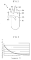
- the overshoot of the refrigerant temperature decreases the temperature of residual refrigeration oil in the low pressure side of the refrigerant circuit (10) to increase the viscosity of the refrigeration oil (see Figure 3). Therefore, it becomes difficult in this case to remove refrigeration oil through refrigerant circulation.
- the compressor (21) is controlled by a command from the compressor control section (50) to run so that the refrigerant temperature in the low pressure side of the refrigerant circuit (10) can reach or exceed a predetermined value, i.e., so that the overshoot of the refrigerant temperature can be prevented.
- the compressor (21) stepwise increases its frequency for a predetermined time period (T2) from its activation, i.e., for an initial stage of each recovery operation time period ( T1 ), and then continuously runs with a constant frequency until the end of the recovery operation. This prevents an abrupt start-up of the compressor (21), which prevents an overshoot of the refrigerant temperature.
- the recovery operation time period (T1) is a time period from the activation of the compressor (21) to the deactivation thereof.
- Each indoor expansion valve (32) is controlled by a command from the valve control section (60) to change its opening according to the stepwise increase of the frequency of the compressor (21).
- the opening control on each indoor expansion valve (32) is carried out by stepwise increasing the opening during the predetermined time period (T2) from the activation of the compressor (21), i.e., during a time period when the frequency of the compressor (21) stepwise increases, and then controlling the opening until the end of the recovery operation so that the refrigerant can have a constant degree of superheat as during the normal operation.
- each indoor expansion valve (32) increases according to the amount of refrigerant sucked into the compressor (21) and, in each indoor heat exchanger (33), refrigerant is surely held at a predetermined degree of superheat. This prevents a temperature drop of refrigerant in the low pressure side of the refrigerant circuit (10).
- each indoor fan (33a) is driven from before the start of each recovery operation, i.e., from before the activation of the compressor (21), and continuously driven with a maximum airflow (MAX) until the end of the recovery operation.
- MAX maximum airflow
- the indoor fan (33a) continuously takes room air to the indoor heat exchanger (33) and, therefore, refrigerant surely exchanges heat with room air to evaporate. Therefore, refrigerant in the low pressure side of the refrigerant circuit (10) can be prevented from decreasing its pressure and temperature during the recovery operation.
- the compressor control section (50) is provided to stepwise increase the frequency of the compressor (21) during an initial stage of each recovery operation, an abrupt drop in the refrigerant temperature, i.e., a so-called overshoot of the refrigerant temperature, in the low pressure side of the refrigerant circuit (10) can be prevented.
- This prevents a temperature drop of residual refrigeration oil in the low pressure side of the refrigerant circuit (10) and, therefore, prevents a viscosity increase of the refrigeration oil.
- the refrigeration oil can be easily removed and carried away through refrigerant circulation, which improves the pipe cleaning performance.
- valve control section (60) is provided to stepwise increase the opening of each indoor expansion valve (32) according to the increase in the frequency of the compressor (21), i.e., the amount of refrigerant sucked into the compressor (21), the refrigerant in each indoor heat exchanger (33) can be held at a predetermined degree of superheat. This surely prevents the refrigerant temperature in the low pressure side of the refrigerant circuit (10) from decreasing.
- the fan control section (70) is provided to continuously drive each indoor fan (33a) from prior to each recovery operation, i.e., from prior to the activation of the compressor (21), to the end of the recovery operation, this ensures that at least while refrigerant flows through each indoor heat exchanger (33), refrigerant in each indoor heat exchanger (33) surely exchanges heat with room air to evaporate.
- the refrigerant temperature in the low pressure side of the refrigerant circuit (10) can be prevented from decreasing.
- each indoor fan (33a) is driven with a maximum airflow under the control of the fan control section (70), refrigerant in each indoor heat exchanger (33) can be surely evaporated.
- the above embodiment may have the following configurations.
- the above embodiment is configured to circulate refrigerant through the refrigerant circuit (10) so that it can flow through all (three) indoor heat exchangers (33).
- refrigerant may be circulated through the refrigerant circuit (10) so that it can flow through only one arbitrarily selected from the three indoor heat exchangers (33) and then sequentially flow through the remaining two indoor heat exchangers (33) in this manner.
- this refrigerant circulation is carried out by fully closing the indoor expansion valves (32) for the remaining two indoor heat exchangers (33) except for the arbitrarily selected one.
- the above embodiment describes the case of using three indoor units (30). Needless to say, a single or a plurality of indoor units may be used.
- the present invention is useful as a refrigeration system capable of cleaning the refrigerant pipes.
Landscapes
- Engineering & Computer Science (AREA)
- Physics & Mathematics (AREA)
- Mechanical Engineering (AREA)
- Thermal Sciences (AREA)
- General Engineering & Computer Science (AREA)
- Chemical & Material Sciences (AREA)
- Analytical Chemistry (AREA)
- Power Engineering (AREA)
- Air Conditioning Control Device (AREA)
- Compression-Type Refrigeration Machines With Reversible Cycles (AREA)
Applications Claiming Priority (2)
| Application Number | Priority Date | Filing Date | Title |
|---|---|---|---|
| JP2003295322A JP3767586B2 (ja) | 2003-08-19 | 2003-08-19 | 冷凍装置 |
| PCT/JP2004/011895 WO2005017423A1 (fr) | 2003-08-19 | 2004-08-19 | Dispositif congelateur |
Publications (1)
| Publication Number | Publication Date |
|---|---|
| EP1662214A1 true EP1662214A1 (fr) | 2006-05-31 |
Family
ID=34191092
Family Applications (1)
| Application Number | Title | Priority Date | Filing Date |
|---|---|---|---|
| EP04771856A Withdrawn EP1662214A1 (fr) | 2003-08-19 | 2004-08-19 | Dispositif congelateur |
Country Status (7)
| Country | Link |
|---|---|
| US (1) | US7624583B2 (fr) |
| EP (1) | EP1662214A1 (fr) |
| JP (1) | JP3767586B2 (fr) |
| KR (1) | KR100732804B1 (fr) |
| CN (1) | CN100443833C (fr) |
| AU (1) | AU2004264485B2 (fr) |
| WO (1) | WO2005017423A1 (fr) |
Cited By (2)
| Publication number | Priority date | Publication date | Assignee | Title |
|---|---|---|---|---|
| EP2679931A1 (fr) * | 2012-06-28 | 2014-01-01 | Mitsubishi Heavy Industries, Ltd. | Climatiseur |
| EP2436993A4 (fr) * | 2009-05-29 | 2014-07-23 | Daikin Ind Ltd | Dispositif de climatisation conçu spécialement pour le chauffage |
Families Citing this family (13)
| Publication number | Priority date | Publication date | Assignee | Title |
|---|---|---|---|---|
| US7584625B2 (en) * | 2005-10-21 | 2009-09-08 | Emerson Climate Technologies, Inc. | Compressor capacity modulation system and method |
| US8826680B2 (en) * | 2005-12-28 | 2014-09-09 | Johnson Controls Technology Company | Pressure ratio unload logic for a compressor |
| JP4258553B2 (ja) * | 2007-01-31 | 2009-04-30 | ダイキン工業株式会社 | 熱源ユニット及び冷凍装置 |
| US8452459B2 (en) * | 2009-08-31 | 2013-05-28 | Fisher-Rosemount Systems, Inc. | Heat exchange network heat recovery optimization in a process plant |
| EP2469195B1 (fr) * | 2009-09-29 | 2017-10-25 | Mitsubishi Electric Corporation | Machine de conditionnement d'air et de chauffage d'eau à accumulation de chaleur |
| US8950202B2 (en) * | 2010-01-29 | 2015-02-10 | Daikin Industries, Ltd. | Heat pump system |
| EP2532990A4 (fr) * | 2010-02-04 | 2014-04-09 | Maekawa Seisakusho Kk | Pompe à chaleur, et procédé de mise en uvre de pompe à chaleur |
| JP6529601B2 (ja) * | 2015-11-20 | 2019-06-12 | 三菱電機株式会社 | 冷凍サイクル装置及び冷凍サイクル装置の制御方法 |
| CN110411054B (zh) * | 2019-07-09 | 2021-02-02 | 南京天加环境科技有限公司 | 一种可降低润滑油温度的燃气热泵空调系统及控制方法 |
| CN110411082B (zh) * | 2019-07-23 | 2020-10-23 | 珠海格力电器股份有限公司 | 冷媒回收系统及其控制方法、装置、控制器和空调系统 |
| CN110986257B (zh) * | 2019-12-17 | 2023-05-26 | 珠海格力电器股份有限公司 | 一种多联机系统清洗方法、装置及空调设备 |
| CN111023476B (zh) * | 2019-12-19 | 2021-10-01 | Tcl空调器(中山)有限公司 | 一种压缩机运行频率调节方法、存储介质及空调 |
| US12420611B2 (en) * | 2023-12-14 | 2025-09-23 | Rivian Ip Holdings, Llc | Bypass for heat pump systems |
Family Cites Families (12)
| Publication number | Priority date | Publication date | Assignee | Title |
|---|---|---|---|---|
| JPS61110834A (ja) | 1984-11-02 | 1986-05-29 | Hitachi Ltd | 空気調和機の制御方法 |
| JPS6373052A (ja) | 1986-09-13 | 1988-04-02 | ダイキン工業株式会社 | 冷凍装置の油回収運転制御装置 |
| JPH0784971B2 (ja) | 1989-04-11 | 1995-09-13 | ダイキン工業株式会社 | 空気調和装置の運転制御装置 |
| JPH0784971A (ja) * | 1993-06-28 | 1995-03-31 | Canon Inc | コンピュータシステム |
| JP3732907B2 (ja) | 1996-12-12 | 2006-01-11 | 三洋電機株式会社 | 空気調和機およびその冷凍機油回収方法 |
| JPH115439A (ja) * | 1997-06-17 | 1999-01-12 | Denso Corp | 車両用空気調和装置 |
| JP2000055488A (ja) * | 1998-08-05 | 2000-02-25 | Sanden Corp | 冷凍装置 |
| KR100332764B1 (ko) | 1999-05-27 | 2002-04-17 | 구자홍 | 인버터 열펌프의 기동 알고리즘 |
| JP4169875B2 (ja) | 1999-08-03 | 2008-10-22 | 三菱電機株式会社 | 冷凍サイクル装置 |
| CN100400983C (zh) * | 2001-01-10 | 2008-07-09 | 广东科龙电器股份有限公司 | 制冷系统及其回油方法 |
| CN1183366C (zh) * | 2001-06-15 | 2005-01-05 | 广东科龙电器股份有限公司 | 制冷系统的回油控制方法 |
| JP7084971B2 (ja) * | 2020-10-05 | 2022-06-15 | ソフトバンク株式会社 | システム、サーバ、プログラム、及び情報処理方法 |
-
2003
- 2003-08-19 JP JP2003295322A patent/JP3767586B2/ja not_active Expired - Fee Related
-
2004
- 2004-08-19 US US10/566,726 patent/US7624583B2/en not_active Expired - Fee Related
- 2004-08-19 WO PCT/JP2004/011895 patent/WO2005017423A1/fr not_active Ceased
- 2004-08-19 EP EP04771856A patent/EP1662214A1/fr not_active Withdrawn
- 2004-08-19 AU AU2004264485A patent/AU2004264485B2/en not_active Ceased
- 2004-08-19 KR KR1020067002572A patent/KR100732804B1/ko not_active Expired - Fee Related
- 2004-08-19 CN CNB2004800237153A patent/CN100443833C/zh not_active Expired - Fee Related
Non-Patent Citations (1)
| Title |
|---|
| See references of WO2005017423A1 * |
Cited By (2)
| Publication number | Priority date | Publication date | Assignee | Title |
|---|---|---|---|---|
| EP2436993A4 (fr) * | 2009-05-29 | 2014-07-23 | Daikin Ind Ltd | Dispositif de climatisation conçu spécialement pour le chauffage |
| EP2679931A1 (fr) * | 2012-06-28 | 2014-01-01 | Mitsubishi Heavy Industries, Ltd. | Climatiseur |
Also Published As
| Publication number | Publication date |
|---|---|
| AU2004264485B8 (en) | 2005-02-24 |
| KR100732804B1 (ko) | 2007-06-27 |
| CN100443833C (zh) | 2008-12-17 |
| US20060185376A1 (en) | 2006-08-24 |
| CN1839287A (zh) | 2006-09-27 |
| AU2004264485A1 (en) | 2005-02-24 |
| AU2004264485B2 (en) | 2007-11-22 |
| WO2005017423A1 (fr) | 2005-02-24 |
| JP3767586B2 (ja) | 2006-04-19 |
| JP2005061774A (ja) | 2005-03-10 |
| KR20060058103A (ko) | 2006-05-29 |
| US7624583B2 (en) | 2009-12-01 |
Similar Documents
| Publication | Publication Date | Title |
|---|---|---|
| US7624583B2 (en) | Freezer device | |
| EP3760950A1 (fr) | Système de réfrigération comportant une purge et un filtre d'acide | |
| EP1150080A2 (fr) | Appareil de circulation de frigorigène et procédé d'assemblage d'un circuit de frigorigène | |
| US7497091B2 (en) | Refrigeration device | |
| JP4110818B2 (ja) | 冷凍装置 | |
| JP5458717B2 (ja) | 冷凍装置 | |
| US7104086B2 (en) | Refrigeration apparatus | |
| JP4164566B2 (ja) | 空気調和装置 | |
| JP4052478B2 (ja) | 空気調和システムの冷凍機油分離回収システムおよび洗浄方法 | |
| AU2006241937A1 (en) | Air conditioner, heat source unit, and air conditioner updating method | |
| JP4281734B2 (ja) | 冷凍装置 | |
| JP4605784B2 (ja) | 室外機と室内機との連絡配管の洗浄用の運転モードを備えたエンジン駆動式ヒートポンプとその運転方法 | |
| JP2006064378A5 (fr) | ||
| JP3700723B2 (ja) | 冷凍装置 | |
| JP3933079B2 (ja) | 冷凍装置およびその配管洗浄方法 | |
| JP2004218931A (ja) | 空気調和装置の配管洗浄方法及び空気調和装置 | |
| KR100709595B1 (ko) | 냉동장치 | |
| JP2004301404A (ja) | 空気調和装置の配管洗浄方法 | |
| JP2004340430A (ja) | 冷凍装置 | |
| JP2004293883A (ja) | 空気調和装置の配管洗浄方法 |
Legal Events
| Date | Code | Title | Description |
|---|---|---|---|
| PUAI | Public reference made under article 153(3) epc to a published international application that has entered the european phase |
Free format text: ORIGINAL CODE: 0009012 |
|
| 17P | Request for examination filed |
Effective date: 20060221 |
|
| AK | Designated contracting states |
Kind code of ref document: A1 Designated state(s): AT BE BG CH CY CZ DE DK EE ES FI FR GB GR HU IE IT LI LU MC NL PL PT RO SE SI SK TR |
|
| RIN1 | Information on inventor provided before grant (corrected) |
Inventor name: YOSHIMI, MANABUC/O KANAOKA FACTORY, SAKAI PLANT Inventor name: YOSHIMI, ATSUSHIC/O KANAOKA FACTORY, SAKAI PLANT |
|
| DAX | Request for extension of the european patent (deleted) | ||
| STAA | Information on the status of an ep patent application or granted ep patent |
Free format text: STATUS: THE APPLICATION HAS BEEN WITHDRAWN |
|
| 18W | Application withdrawn |
Effective date: 20130724 |