EP1662880B1 - Four de boulanger avec dispositif de production de vapeur - Google Patents
Four de boulanger avec dispositif de production de vapeur Download PDFInfo
- Publication number
- EP1662880B1 EP1662880B1 EP04737663.7A EP04737663A EP1662880B1 EP 1662880 B1 EP1662880 B1 EP 1662880B1 EP 04737663 A EP04737663 A EP 04737663A EP 1662880 B1 EP1662880 B1 EP 1662880B1
- Authority
- EP
- European Patent Office
- Prior art keywords
- oven
- steam
- chamber
- heating
- steam generation
- Prior art date
- Legal status (The legal status is an assumption and is not a legal conclusion. Google has not performed a legal analysis and makes no representation as to the accuracy of the status listed.)
- Expired - Lifetime
Links
Images




Classifications
-
- A—HUMAN NECESSITIES
- A21—BAKING; EDIBLE DOUGHS
- A21B—BAKERS' OVENS; MACHINES OR EQUIPMENT FOR BAKING
- A21B3/00—Parts or accessories of ovens
- A21B3/04—Air-treatment devices for ovens, e.g. regulating humidity
-
- A—HUMAN NECESSITIES
- A21—BAKING; EDIBLE DOUGHS
- A21B—BAKERS' OVENS; MACHINES OR EQUIPMENT FOR BAKING
- A21B1/00—Bakers' ovens
- A21B1/42—Bakers' ovens characterised by the baking surfaces moving during the baking
- A21B1/44—Bakers' ovens characterised by the baking surfaces moving during the baking with surfaces rotating in a horizontal plane
-
- Y—GENERAL TAGGING OF NEW TECHNOLOGICAL DEVELOPMENTS; GENERAL TAGGING OF CROSS-SECTIONAL TECHNOLOGIES SPANNING OVER SEVERAL SECTIONS OF THE IPC; TECHNICAL SUBJECTS COVERED BY FORMER USPC CROSS-REFERENCE ART COLLECTIONS [XRACs] AND DIGESTS
- Y02—TECHNOLOGIES OR APPLICATIONS FOR MITIGATION OR ADAPTATION AGAINST CLIMATE CHANGE
- Y02P—CLIMATE CHANGE MITIGATION TECHNOLOGIES IN THE PRODUCTION OR PROCESSING OF GOODS
- Y02P60/00—Technologies relating to agriculture, livestock or agroalimentary industries
- Y02P60/80—Food processing, e.g. use of renewable energies or variable speed drives in handling, conveying or stacking
Definitions
- the invention relates to a baker's oven with an internal steaming device.
- the invention is particularly suitable for, but not limited to, rotary bakers' ovens; but can be readily adapted to conventional bakers' ovens.
- a well known and widely used baker's oven comprises a number of superimposed oven compartments with individual oven doors at the front.
- Each compartment generally includes two turntables onto which bakery goods including bread pins are loaded.
- the oven compartments are heated by electric heating elements in the bottom and top of the compartments.
- the heating elements are formed as single heating units comprising a number of parallel arms connected in series by U-shaped elements.
- the parallel arms extend from the oven door to the rear of the compartment and are spaced across the width of the oven.
- the covered steam generation chamber is an elongate chamber adjacent to at least one elongate heating chamber containing at least one heating element.
- the steam generation chamber is separated from the at least one heating chamber by a dividing wall.
- the heating chamber has one or more heat outlets to enable the transfer of the heat generated by the heating element(s) to the oven compartment.
- the or each heat sink member is a strip of bar of metal, eg., mild steel, having a thermal mass sufficient to maintain the temperature within the oven compartment within a prescribed temperature range when the steaming water is introduced into the steaming compartment and converted to steam.
- the heat sink members are heated by heat transferred from the heating rods in the heating chamber to the steam chamber.
- the water for steaming is introduced into the steam chamber by a water pipe, preferably located at or adjacent the closed end of the steam chamber.
- the water pipe is preferably positioned towards the front of the oven compartment and extends transversely of the steaming chamber.
- the steaming water enters the steaming chamber at or adjacent the closed end and the water and generated steam progress down the steaming chamber and exit the steam chamber at the at least one steam outlet.
- all of the steaming water is converted to steam by heat from the ballast bar before the water has travelled three quarters of the length of the steaming chamber and preferably within one half to three quarters of the length of the heating element.
- the steam element preferably directs the steam into the oven compartment into a zone (or zones) at the rear of the oven and away from direct contact with an ceramic surfaces. This zone or zones may be above the bakery products.
- ovens As steam is only needed in the production of about 20% of a typical bakery's products, the oven needs to be used in non steaming mode most of the time. Accordingly, ovens provided with internal steaming devices must be able to allow heat to dissipate freely and evenly from the heating rods throughout the oven.
- the heating chamber is provided with a plurality of heating outlets along the length of the heating chamber. These outlets are provided in the side of the heating chamber to prevent the outlets being blocked by product debris falling onto the heating chamber.
- the steam outlet is towards the rear of the compartment away from any ceramic surfaces in the oven and the steaming water is introduced through a water pipe which extends transversely of the covered steam generation chamber.
- More than one steam generation chamber may be provided in the oven adjacent a respective heating element, preferably a parallel section heating element which extends from the vicinity of the front of the oven towards the rear.
- the baker's oven is a rotary oven 10 of the type sold under the registered trade mark "ROTEL".
- the oven has five lengths with two oven compartments 11 on each level.
- a drive motor 12 is operably connected to a pair of vertical shafts 13 on which are mounted turntables 14 which may incorporate optional ceramic "tiles” 15 on which the bakery products (not shown) are cooked.
- Each oven compartment 11 has an oven door 16 operably openable and closable by a handle 17.
- Each oven compartment 11 has at least a pair of top heating elements 18 mounted to the under side of the top wall 19 of the oven compartment 11. As shown in more detail in Figure 2 , each oven compartment 11 has a pair of substantially U-shaped inner heating elements 20 and a pair of outer heating elements 21 mounted on the bottom wall 19a, where the pairs of outer elements 21 have a substantially straight element leg 22 connected to a curved element leg 23 which lies adjacent the peripheral walls 24 of the oven compartment 11.
- the operation of the heating elements 20, 21 is controlled by a computerised control system (not shown) which also controls the operation of the steaming apparatus to be hereinafter described.
- a respective steaming apparatus 30 is associated with the straight leg 22 of an outer heating element 21 and a respective steaming apparatus 50 is associated with both legs, 25, 26 of a U-shaped inner heating element 20.
- the steaming apparatus 30 has a housing formed from two folded blanks 31, 32, formed from stainless steel, to form an elongate heating chamber 33, in which is received most of the straight leg 22 of a heating element 21. Holes (not shown) in the outer wall 34 of the heating chamber 33 allow the transfer of heat from the heating element 21 to the oven compartment 11.
- An elongate steam chamber 35 lies adjacent the heating chamber 33 and is separated therefrom by a dividing wall 36.
- the steaming chamber 35 is closed at one end and is provided with at least one slot or opening (not shown) at or adjacent the other end to provide a steam outlet for the steam generated within the steam chamber.
- a heat sink member 37 comprising a strip of mild steel, is provided in the steam chamber 35.
- a water pipe 41 extends transversely of the steaming apparatus 30, adjacent closed end of the steam chamber 35, and is provided with at least one nozzle to direct the steaming water 42 onto the heat sink member 37 to enable the steaming water 52 to be converted to steam as it travels along the steam chamber 36 towards the steam outlet.
- the dimension of the heat sink member 37(and its material composition) are selected to ensure that the heat sink member 37 has sufficient thermal mass to convert all of the steaming water 42 into steam before it exits from the steam chamber 35; while minimizing any temperature drop within the oven compartment 11 to less than, say 5°C-10°C during the steaming step.
- all the steaming water 42 is converted to steam by heat from the ballast bars 37 before the water has travelled three quarters of the length of the steaming chamber and preferably within one half to three quarters of the length of the steam chamber 35.
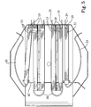
- Figure 5 is an alternative single oven arrangement in which the identical features are identified by similar numbers to that of Figure 2 .
- the steaming apparatus 50 for an inner heating element 20 is of substantially mirror-image about its central axis to form heating chambers 53 for the legs 35, 26 of the heating element 20, and respective steam chambers 55 with respective heat sinks 57.
- the water pipe 40 extends transversely to the steam chambers 55 to enable steaming water 42 to be sprayed by nozzles 41 onto the heat sink members 57.
- FIG. 6 is a top plan view of the top cover 51 of the steaming apparatus 50.
- the top cover 51 has a plurality of holes 58 in the outer side walls 54 to allow heat to be transferred from the legs 25, 26 of the heating element 20 to the oven compartment 11, and the steam outlets 59 are shown at the end of the steam chambers 55 formed in the top surfaces 60 spaced from the closed ends adjacent the water pipe 40.
- the steam released from the steam outlets 59 of the steaming apparatus 30, 50 is directed towards the rear portion of the peripheral wall 24 of the oven compartment 11, as indicated by the arrows A, so that the steam passes between the turntable 14 and the rear wall of the oven.
- the steam is thus directed into the portion of the oven compartment 11 generally above the bakery products and not directed into the ceramic tiles 15, supported by the turntable 14 on which the bakery products are cooked.
- the oven of the present invention comprises a heat stable efficient steam generation device for the oven compartments 11 of the baker's oven 10. While a rotary baker's oven 10 has been illustrated, it will be readily apparent to the skilled address that the invention can be applied to conventional baker's ovens.
Landscapes
- Life Sciences & Earth Sciences (AREA)
- Engineering & Computer Science (AREA)
- Food Science & Technology (AREA)
- Baking, Grill, Roasting (AREA)
- Cookers (AREA)
- Bakery Products And Manufacturing Methods Therefor (AREA)
Claims (3)
- Four de boulanger (10) présentant au moins un compartiment de four (11), le compartiment de four (11) étant chauffé par au moins un élément chauffant (21, 22, 25, 26) comportant
une pluralité de sections chauffantes parallèles agencées sur toute l'étendue de la largeur du compartiment de four, chacune des sections chauffantes parallèles comprenant une chambre de génération de vapeur (35, 55), située à côté d'au moins une chambre chauffante allongée renfermant au moins un élément chauffant (21, 22, 25, 26), ladite au moins une chambre chauffante (33, 53) étant à côté de la chambre de génération de vapeur (35, 55) et séparée de celle-ci par une paroi de division (36) ;
au moins un élément dissipateur de chaleur (37) étant fourni dans la chambre de génération de vapeur (35, 55) pour fournir une source de chaleur afin de convertir l'eau fumante introduite dans la chambre de génération de vapeur (35, 55) en vapeur ; et
un tuyau d'eau fumante (40) présentant au moins un ajutage (41) capable de fonctionner pour diriger l'eau sur l'au moins un dissipateur de chaleur à l'intérieur de la chambre de génération de vapeur (35, 55),
caractérisé en ce qu'une pluralité de sorties de chaleur (58) est formée dans le côté de la chambre chauffante (33, 53) pour fournir un accès direct de la chambre chauffante (33, 53) à la chambre de four (11) afin de permettre le transfert de chaleur de l'au moins un élément chauffant au compartiment de four (11) ; et dans lequel la chambre de génération de vapeur est couverte, fermée à une extrémité, et forme un conduit allongé muni d'au moins une sortie de vapeur (59) au niveau ou à côté de l'autre extrémité ; l'eau fumante (42) étant convertible en vapeur à l'intérieur de la chambre de génération de vapeur (35, 55) et étant libérable dans le compartiment de four (11) par ledit au moins une sortie de vapeur (59). - Four de boulanger selon la revendication 1, dans lequel l'au moins un élément dissipateur de chaleur (37) est une bande de bar métallique présentant une masse thermique suffisante pour maintenir la température à l'intérieur du compartiment de four dans les limites d'une plage de température prescrite.
- Four de boulanger selon la revendication 1 ou 2 dans lequel la sortie de vapeur (59) de la chambre de génération de vapeur est positionnée vers l'arrière du compartiment de four.
Applications Claiming Priority (2)
| Application Number | Priority Date | Filing Date | Title |
|---|---|---|---|
| AU2003904149A AU2003904149A0 (en) | 2003-08-07 | 2003-08-07 | Steaming method and apparatus for baker's oven |
| PCT/AU2004/001049 WO2005013697A1 (fr) | 2003-08-07 | 2004-08-06 | Dispositif d'etuvage pour fours de boulanger |
Publications (3)
| Publication Number | Publication Date |
|---|---|
| EP1662880A1 EP1662880A1 (fr) | 2006-06-07 |
| EP1662880A4 EP1662880A4 (fr) | 2013-12-11 |
| EP1662880B1 true EP1662880B1 (fr) | 2018-10-10 |
Family
ID=32476439
Family Applications (1)
| Application Number | Title | Priority Date | Filing Date |
|---|---|---|---|
| EP04737663.7A Expired - Lifetime EP1662880B1 (fr) | 2003-08-07 | 2004-08-06 | Four de boulanger avec dispositif de production de vapeur |
Country Status (6)
| Country | Link |
|---|---|
| US (1) | US7985944B2 (fr) |
| EP (1) | EP1662880B1 (fr) |
| AU (1) | AU2003904149A0 (fr) |
| CA (1) | CA2534926C (fr) |
| NZ (1) | NZ545073A (fr) |
| WO (1) | WO2005013697A1 (fr) |
Families Citing this family (5)
| Publication number | Priority date | Publication date | Assignee | Title |
|---|---|---|---|---|
| AU2009227879B2 (en) * | 2008-10-31 | 2013-10-10 | Moffat Pty Limited | A method of baking and an oven |
| NZ580537A (en) * | 2008-10-31 | 2010-10-29 | Moffat Pty Ltd | Baking oven with active heating region under tray made by elements with active and inactive portions |
| US9903597B2 (en) * | 2010-04-28 | 2018-02-27 | Sharp Kabushiki Kaisha | Cooking device including buffer chamber |
| EP3382286B1 (fr) * | 2017-03-29 | 2020-01-01 | Vestel Elektronik Sanayi ve Ticaret A.S. | Appareil à vapeur pour un four classique |
| CN115335640A (zh) * | 2020-04-16 | 2022-11-11 | V-楚格股份公司 | 烹饪装置 |
Family Cites Families (10)
| Publication number | Priority date | Publication date | Assignee | Title |
|---|---|---|---|---|
| FR336610A (fr) * | 1903-11-03 | 1904-03-14 | Guillaume Bouvier | Appareil producteur de vapeur d'eau pour fours de boulangers, patissiers, etc. |
| FR338514A (fr) * | 1903-12-30 | 1904-05-26 | Joseph Antoine Lombard | Appareil à produire de la buée dans les fours de boulangers et autres |
| SU1158140A1 (ru) * | 1983-09-12 | 1985-05-30 | Всесоюзный научно-исследовательский институт хлебопекарной промышленности | Хлебопекарна печь |
| US4646630A (en) * | 1985-03-25 | 1987-03-03 | The Lucks Company | Humidifier assembly |
| JPS6313574U (fr) * | 1986-07-14 | 1988-01-28 | ||
| US4724824A (en) | 1986-08-22 | 1988-02-16 | The Lucks Company | Instantaneous steam generator |
| AU666633B2 (en) * | 1992-04-30 | 1996-02-15 | Moffat Pty Limited | Electrically heated rotary baker's oven |
| AU669838B2 (en) * | 1992-04-30 | 1996-06-20 | Moffat Pty Limited | Electrically heated rotary baker's oven |
| AU666365B2 (en) * | 1992-04-30 | 1996-02-08 | Moffat Pty Limited | Electrically heated rotary baker's oven |
| DE10044466B4 (de) * | 2000-09-08 | 2011-06-16 | Werner & Pfleiderer Lebensmitteltechnik Gmbh | Beschwadungsvorrichtung |
-
2003
- 2003-08-07 AU AU2003904149A patent/AU2003904149A0/en not_active Abandoned
-
2004
- 2004-08-06 NZ NZ545073A patent/NZ545073A/en not_active IP Right Cessation
- 2004-08-06 US US10/567,417 patent/US7985944B2/en active Active
- 2004-08-06 WO PCT/AU2004/001049 patent/WO2005013697A1/fr not_active Ceased
- 2004-08-06 CA CA2534926A patent/CA2534926C/fr not_active Expired - Lifetime
- 2004-08-06 EP EP04737663.7A patent/EP1662880B1/fr not_active Expired - Lifetime
Non-Patent Citations (1)
| Title |
|---|
| None * |
Also Published As
| Publication number | Publication date |
|---|---|
| CA2534926C (fr) | 2012-05-01 |
| NZ545073A (en) | 2009-02-28 |
| AU2003904149A0 (en) | 2003-08-21 |
| US20080257878A1 (en) | 2008-10-23 |
| CA2534926A1 (fr) | 2005-02-17 |
| EP1662880A1 (fr) | 2006-06-07 |
| US7985944B2 (en) | 2011-07-26 |
| EP1662880A4 (fr) | 2013-12-11 |
| WO2005013697A1 (fr) | 2005-02-17 |
Similar Documents
| Publication | Publication Date | Title |
|---|---|---|
| AU2009227878B2 (en) | A baker's oven | |
| US4834063A (en) | Food cooking oven with duct fingers and method | |
| US4377109A (en) | Apparatus for baking food products such as pizzas and the like | |
| EP2074369B1 (fr) | Fours à air projeté munis d'orifices à écoulement massique élevé | |
| EP1797758B1 (fr) | Système de cuisson continue | |
| BRPI0309916B1 (pt) | Forno de cozimento em velocidade | |
| EP1517096A1 (fr) | Four à convection et système associé d'écoulement d'air | |
| EP1172022B1 (fr) | Four a micro-ondes/convection multi-plateaux | |
| US6716467B2 (en) | Food oven with even heat distribution | |
| JP2012010711A (ja) | パン屋、ペストリーショップ、ケーキ屋の製品、または類似する製品の加熱調理オーブン | |
| CA2534926C (fr) | Dispositif d'etuvage pour fours de boulanger | |
| EP0370021A1 (fr) | Procede et appareil de chauffage et de cuisson de produits alimentaires par impulsions | |
| US4827106A (en) | Self-cleaning convection oven | |
| AU2004262443B2 (en) | Steaming device for baker's ovens | |
| ITBO20070579A1 (it) | Forno a tunnel per prodotti alimentari, in particolare per prodotti da forno, quali pizze, focacce e simili. | |
| GB2245136A (en) | Rotary bakers' oven | |
| SU1194348A1 (ru) | Хлебопекарна печь | |
| US7804049B2 (en) | Electrically powered oven, in particular for baking or heating sliced bread, and heating procedure | |
| RU2081584C1 (ru) | Электрическая хлебопекарная печь | |
| SU1708224A1 (ru) | Электрическа печь дл выпечки хлебобулочных и мучных кондитерских изделий | |
| RU12881U1 (ru) | Хлебопекарная печь | |
| JPS5844863Y2 (ja) | 回転式パン焼窯 | |
| GB2083738A (en) | Ovens | |
| JPS58152514A (ja) | 一食分ずつの連続炊飯装置及び方法 | |
| DE202004017824U1 (de) | Vorrichtung zum Garen von Gebäck |
Legal Events
| Date | Code | Title | Description |
|---|---|---|---|
| PUAI | Public reference made under article 153(3) epc to a published international application that has entered the european phase |
Free format text: ORIGINAL CODE: 0009012 |
|
| 17P | Request for examination filed |
Effective date: 20060302 |
|
| AK | Designated contracting states |
Kind code of ref document: A1 Designated state(s): AT BE BG CH CY CZ DE DK EE ES FI FR GB GR HU IE IT LI LU MC NL PL PT RO SE SI SK TR |
|
| DAX | Request for extension of the european patent (deleted) | ||
| A4 | Supplementary search report drawn up and despatched |
Effective date: 20131107 |
|
| RIC1 | Information provided on ipc code assigned before grant |
Ipc: A21B 3/04 20060101AFI20131101BHEP Ipc: A21B 1/44 20060101ALI20131101BHEP |
|
| STAA | Information on the status of an ep patent application or granted ep patent |
Free format text: STATUS: EXAMINATION IS IN PROGRESS |
|
| 17Q | First examination report despatched |
Effective date: 20161207 |
|
| GRAP | Despatch of communication of intention to grant a patent |
Free format text: ORIGINAL CODE: EPIDOSNIGR1 |
|
| STAA | Information on the status of an ep patent application or granted ep patent |
Free format text: STATUS: GRANT OF PATENT IS INTENDED |
|
| INTG | Intention to grant announced |
Effective date: 20180528 |
|
| GRAS | Grant fee paid |
Free format text: ORIGINAL CODE: EPIDOSNIGR3 |
|
| GRAA | (expected) grant |
Free format text: ORIGINAL CODE: 0009210 |
|
| STAA | Information on the status of an ep patent application or granted ep patent |
Free format text: STATUS: THE PATENT HAS BEEN GRANTED |
|
| AK | Designated contracting states |
Kind code of ref document: B1 Designated state(s): AT BE BG CH CY CZ DE DK EE ES FI FR GB GR HU IE IT LI LU MC NL PL PT RO SE SI SK TR |
|
| REG | Reference to a national code |
Ref country code: GB Ref legal event code: FG4D |
|
| REG | Reference to a national code |
Ref country code: AT Ref legal event code: REF Ref document number: 1050168 Country of ref document: AT Kind code of ref document: T Effective date: 20181015 Ref country code: CH Ref legal event code: EP |
|
| REG | Reference to a national code |
Ref country code: DE Ref legal event code: R096 Ref document number: 602004053276 Country of ref document: DE Ref country code: IE Ref legal event code: FG4D |
|
| REG | Reference to a national code |
Ref country code: NL Ref legal event code: MP Effective date: 20181010 |
|
| REG | Reference to a national code |
Ref country code: AT Ref legal event code: MK05 Ref document number: 1050168 Country of ref document: AT Kind code of ref document: T Effective date: 20181010 |
|
| PG25 | Lapsed in a contracting state [announced via postgrant information from national office to epo] |
Ref country code: NL Free format text: LAPSE BECAUSE OF FAILURE TO SUBMIT A TRANSLATION OF THE DESCRIPTION OR TO PAY THE FEE WITHIN THE PRESCRIBED TIME-LIMIT Effective date: 20181010 |
|
| PG25 | Lapsed in a contracting state [announced via postgrant information from national office to epo] |
Ref country code: FI Free format text: LAPSE BECAUSE OF FAILURE TO SUBMIT A TRANSLATION OF THE DESCRIPTION OR TO PAY THE FEE WITHIN THE PRESCRIBED TIME-LIMIT Effective date: 20181010 Ref country code: BG Free format text: LAPSE BECAUSE OF FAILURE TO SUBMIT A TRANSLATION OF THE DESCRIPTION OR TO PAY THE FEE WITHIN THE PRESCRIBED TIME-LIMIT Effective date: 20190110 Ref country code: ES Free format text: LAPSE BECAUSE OF FAILURE TO SUBMIT A TRANSLATION OF THE DESCRIPTION OR TO PAY THE FEE WITHIN THE PRESCRIBED TIME-LIMIT Effective date: 20181010 Ref country code: PL Free format text: LAPSE BECAUSE OF FAILURE TO SUBMIT A TRANSLATION OF THE DESCRIPTION OR TO PAY THE FEE WITHIN THE PRESCRIBED TIME-LIMIT Effective date: 20181010 Ref country code: AT Free format text: LAPSE BECAUSE OF FAILURE TO SUBMIT A TRANSLATION OF THE DESCRIPTION OR TO PAY THE FEE WITHIN THE PRESCRIBED TIME-LIMIT Effective date: 20181010 |
|
| PG25 | Lapsed in a contracting state [announced via postgrant information from national office to epo] |
Ref country code: GR Free format text: LAPSE BECAUSE OF FAILURE TO SUBMIT A TRANSLATION OF THE DESCRIPTION OR TO PAY THE FEE WITHIN THE PRESCRIBED TIME-LIMIT Effective date: 20190111 Ref country code: PT Free format text: LAPSE BECAUSE OF FAILURE TO SUBMIT A TRANSLATION OF THE DESCRIPTION OR TO PAY THE FEE WITHIN THE PRESCRIBED TIME-LIMIT Effective date: 20190210 Ref country code: SE Free format text: LAPSE BECAUSE OF FAILURE TO SUBMIT A TRANSLATION OF THE DESCRIPTION OR TO PAY THE FEE WITHIN THE PRESCRIBED TIME-LIMIT Effective date: 20181010 |
|
| REG | Reference to a national code |
Ref country code: DE Ref legal event code: R097 Ref document number: 602004053276 Country of ref document: DE |
|
| PG25 | Lapsed in a contracting state [announced via postgrant information from national office to epo] |
Ref country code: CZ Free format text: LAPSE BECAUSE OF FAILURE TO SUBMIT A TRANSLATION OF THE DESCRIPTION OR TO PAY THE FEE WITHIN THE PRESCRIBED TIME-LIMIT Effective date: 20181010 Ref country code: DK Free format text: LAPSE BECAUSE OF FAILURE TO SUBMIT A TRANSLATION OF THE DESCRIPTION OR TO PAY THE FEE WITHIN THE PRESCRIBED TIME-LIMIT Effective date: 20181010 |
|
| PLBE | No opposition filed within time limit |
Free format text: ORIGINAL CODE: 0009261 |
|
| STAA | Information on the status of an ep patent application or granted ep patent |
Free format text: STATUS: NO OPPOSITION FILED WITHIN TIME LIMIT |
|
| PG25 | Lapsed in a contracting state [announced via postgrant information from national office to epo] |
Ref country code: SK Free format text: LAPSE BECAUSE OF FAILURE TO SUBMIT A TRANSLATION OF THE DESCRIPTION OR TO PAY THE FEE WITHIN THE PRESCRIBED TIME-LIMIT Effective date: 20181010 Ref country code: EE Free format text: LAPSE BECAUSE OF FAILURE TO SUBMIT A TRANSLATION OF THE DESCRIPTION OR TO PAY THE FEE WITHIN THE PRESCRIBED TIME-LIMIT Effective date: 20181010 Ref country code: RO Free format text: LAPSE BECAUSE OF FAILURE TO SUBMIT A TRANSLATION OF THE DESCRIPTION OR TO PAY THE FEE WITHIN THE PRESCRIBED TIME-LIMIT Effective date: 20181010 |
|
| 26N | No opposition filed |
Effective date: 20190711 |
|
| PG25 | Lapsed in a contracting state [announced via postgrant information from national office to epo] |
Ref country code: SI Free format text: LAPSE BECAUSE OF FAILURE TO SUBMIT A TRANSLATION OF THE DESCRIPTION OR TO PAY THE FEE WITHIN THE PRESCRIBED TIME-LIMIT Effective date: 20181010 |
|
| PG25 | Lapsed in a contracting state [announced via postgrant information from national office to epo] |
Ref country code: TR Free format text: LAPSE BECAUSE OF FAILURE TO SUBMIT A TRANSLATION OF THE DESCRIPTION OR TO PAY THE FEE WITHIN THE PRESCRIBED TIME-LIMIT Effective date: 20181010 |
|
| PG25 | Lapsed in a contracting state [announced via postgrant information from national office to epo] |
Ref country code: CY Free format text: LAPSE BECAUSE OF FAILURE TO SUBMIT A TRANSLATION OF THE DESCRIPTION OR TO PAY THE FEE WITHIN THE PRESCRIBED TIME-LIMIT Effective date: 20181010 |
|
| PG25 | Lapsed in a contracting state [announced via postgrant information from national office to epo] |
Ref country code: HU Free format text: LAPSE BECAUSE OF FAILURE TO SUBMIT A TRANSLATION OF THE DESCRIPTION OR TO PAY THE FEE WITHIN THE PRESCRIBED TIME-LIMIT; INVALID AB INITIO Effective date: 20040806 |
|
| PGFP | Annual fee paid to national office [announced via postgrant information from national office to epo] |
Ref country code: LU Payment date: 20230821 Year of fee payment: 20 |
|
| PGFP | Annual fee paid to national office [announced via postgrant information from national office to epo] |
Ref country code: MC Payment date: 20230823 Year of fee payment: 20 Ref country code: IT Payment date: 20230825 Year of fee payment: 20 Ref country code: IE Payment date: 20230822 Year of fee payment: 20 Ref country code: GB Payment date: 20230822 Year of fee payment: 20 Ref country code: CH Payment date: 20230902 Year of fee payment: 20 |
|
| PGFP | Annual fee paid to national office [announced via postgrant information from national office to epo] |
Ref country code: FR Payment date: 20230822 Year of fee payment: 20 Ref country code: DE Payment date: 20230821 Year of fee payment: 20 Ref country code: BE Payment date: 20230821 Year of fee payment: 20 |
|
| REG | Reference to a national code |
Ref country code: DE Ref legal event code: R071 Ref document number: 602004053276 Country of ref document: DE |
|
| REG | Reference to a national code |
Ref country code: CH Ref legal event code: PL |
|
| REG | Reference to a national code |
Ref country code: GB Ref legal event code: PE20 Expiry date: 20240805 |
|
| REG | Reference to a national code |
Ref country code: BE Ref legal event code: MK Effective date: 20240806 |
|
| REG | Reference to a national code |
Ref country code: IE Ref legal event code: MK9A |
|
| PG25 | Lapsed in a contracting state [announced via postgrant information from national office to epo] |
Ref country code: IE Free format text: LAPSE BECAUSE OF EXPIRATION OF PROTECTION Effective date: 20240806 |
|
| PG25 | Lapsed in a contracting state [announced via postgrant information from national office to epo] |
Ref country code: GB Free format text: LAPSE BECAUSE OF EXPIRATION OF PROTECTION Effective date: 20240805 |
|
| PG25 | Lapsed in a contracting state [announced via postgrant information from national office to epo] |
Ref country code: IE Free format text: LAPSE BECAUSE OF EXPIRATION OF PROTECTION Effective date: 20240806 Ref country code: GB Free format text: LAPSE BECAUSE OF EXPIRATION OF PROTECTION Effective date: 20240805 |